KHH20TN
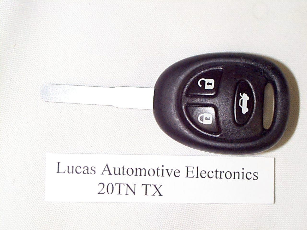
TRW Automotive Electronics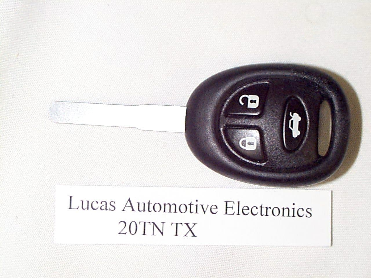
Click to zoom
Application Details
- Equipment Class
- DSC - Part 15 Security/Remote Control Transmitter
- Date of Grant
- Aug 23, 1999
- Application Purpose
- Original Equipment
- Date of Application
- Jun 22, 1999
- Frequency Range
- 315.00000000 - 315.00000000
- Company
- TRW Automotive Electronics
- Country
- United Kingdom
Documents & Files

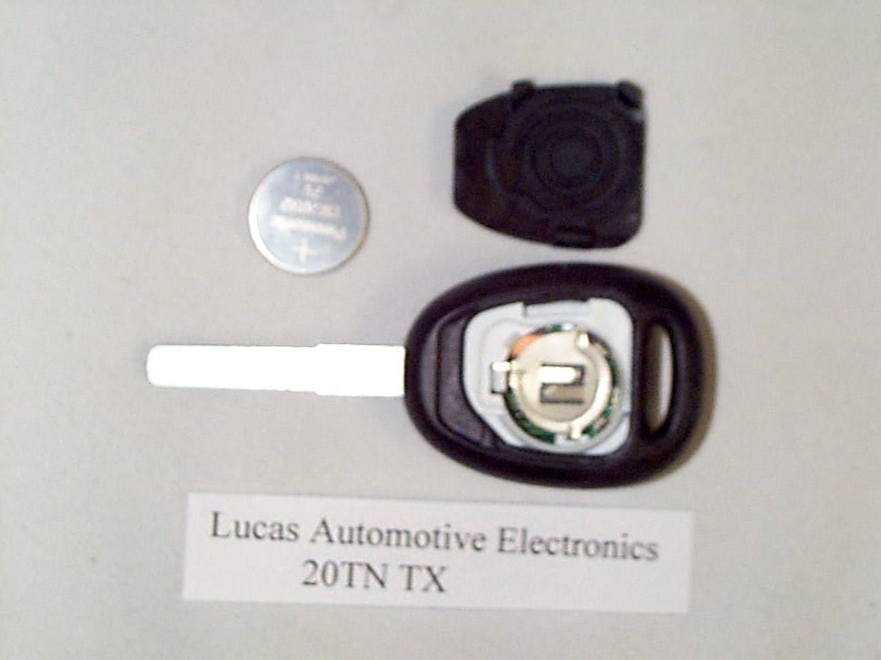
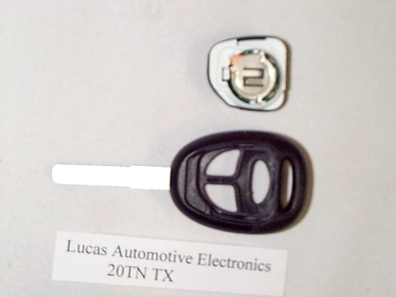
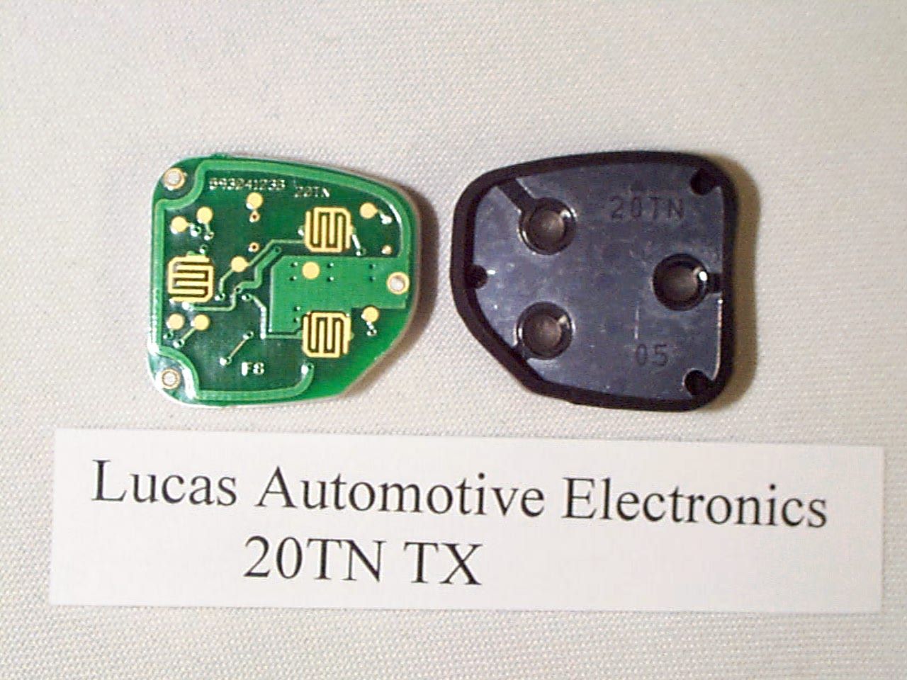

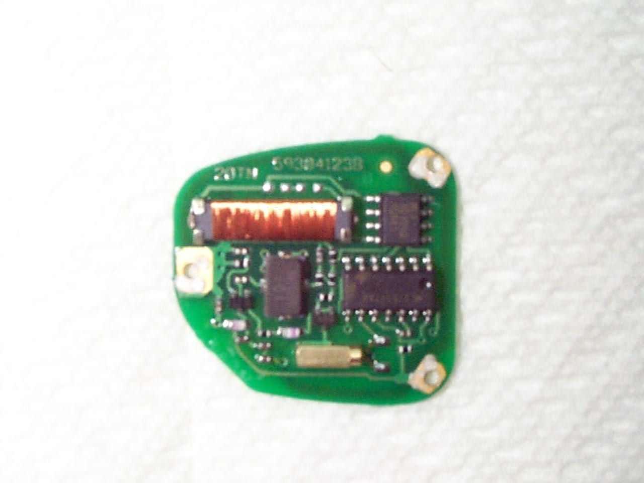
Document Text
Text extracted from the exhibit documents filed with the FCC. Open a document above to read the original.
Users Manual
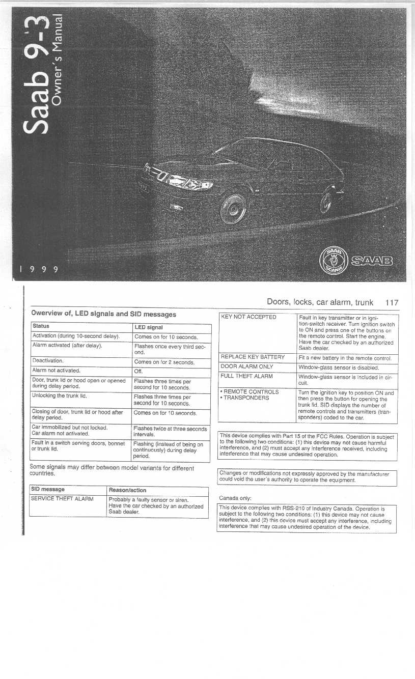
User’s Manual The User’s Manual is not available at this time since the device will be marketed as part of a vehicle. The vehicle manufacturer, Saab, has included the required notices in their manual.
Block Diagram
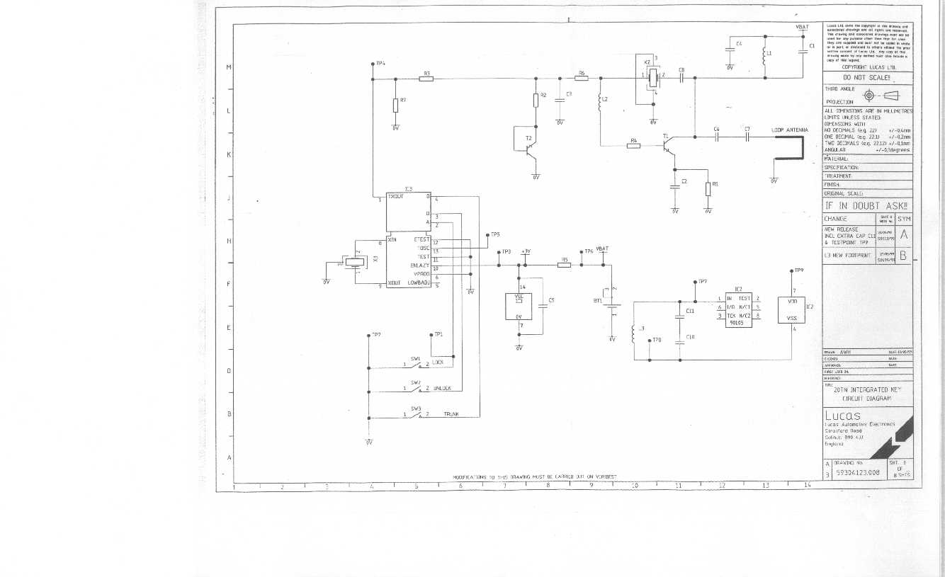
20TN Block Diagram BATTERY+3v TRANSPONDERINTERFACE SECURITY CODEGENERATOR RF MODULATOR LOCK UNLOCK ANTENNA TRUNKUNLOCK ASIC
ID Label/Location Info
Type Approval Label for 20TN in the USA and Canada FCC ID : KHH20TN CANADA 1984 XXX XXXX 9.3 mm 24.3 mm
Operational Description
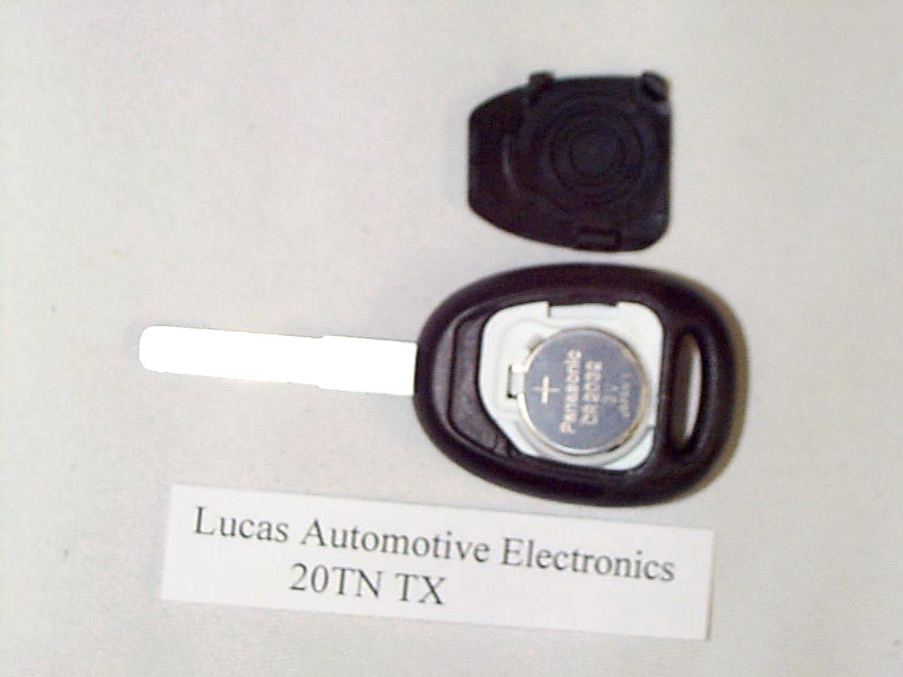
315 MHz 20TN Technical Description Copyright 1999 Lucas Automotive ElectronicsPage 1 of 4 Author: Roger Lee Date: 16 June 1999 Filed as: TechDec315.DOC Updated: 17 June 1999 315 MHz 20TN Technical Description Type DesignationLucas 20TN 315 MHz Radio Key Declaration of Equipment Characteristics TypeTransmitter Frequency Range315 MHz Fixed ± 200kHz Method of Carrier Frequency GenerationSAW Oscillator Adjacent Channel Separation300KHz Class of EmissionL1DCN Type of ModulationPulse width Modulation Signal Input LevelN/A Modulation Input ImpedanceN/A Modulation Bandwidth5KHz Coupling MethodsElectrical Number of Channels1 UtilisationPortable Duplex operationNo AntennaIntegral Alternative AntennaNo Operating Temperature Range-10°C to +55°C Transmitter Rated Output Power 63 dB μ V/m at 3m C.W. 2nd Harmonic Power 40 dB μ V/m at 3m Voltage supply range2.5 to 3.3 V DC Composition of EquipmentSingle Unit Brief Description Of Operation. The product has two sections: an rf generator and a custom chip which provides the data input for the rf section. A block diagram of the 20TN is shown in figure 1. The data is pulse-width encrypted and then amplitude modulated onto the rf carrier using a non-return-to-zero code at a maximum of 1k baud. The clock generator for the coding chip is crystal controlled. The message length is 56 bits. A rolling code system is used for added security. When one of the transmitter buttons (‘lock’, ‘unlock’ or ‘trunk unlock’) is depressed and released, a single burst of rf is transmitted. This transmission is an rf signal amplitude modulated with a pulse train (see figures 2 and 3). If a transmitter button is depressed and held, an extended rf signal is transmitted until the button is released (see figure 4). 315 MHz 20TN Technical Description Copyright 1999 Lucas Automotive Electronics Page 2 of 4 Figure 1 20TN Block Diagram BATTERY+3v TRANSPONDERINTERFACE SECURITY CODEGENERATOR RFMODULATOR LOCK UNLOCK ANTENNA TRUNKUNLOCK ASIC 315 MHz 20TN Technical Description Copyright 1999 Lucas Automotive Electronics Page 3 of 4 Figure 2 Transmitter Output Diagram 27ms pre-amble Data field, 56 data bits including security coding, parity and unit status 315 MHz 20TN Technical Description Copyright 1999 Lucas Automotive Electronics Page 4 of 4 Figure 3 20TN Output with Button Depressed & Released Figure 4 20TN Output with Button Depressed & Held 27 ms 10 ms 10 ms 10ms 16 bits 16 bits 16 bits 56 bits . . . . . . . . . 27 ms 56 bits
Test Report
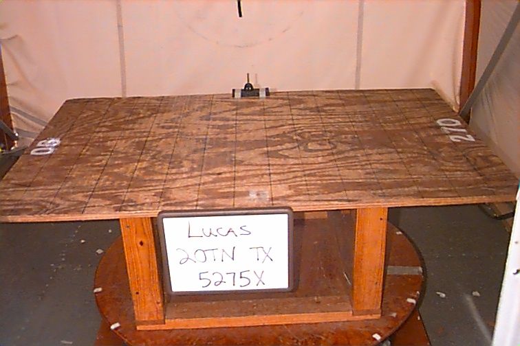
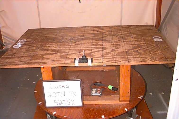
FCC CERTIFICATION REPORT for Lucas Automotive Electronics Stratford Road Solihull England B90 4GW FCC ID: KHH20TN June 21, 1999 WLL PROJECT #: 5275X This report may not be reproduced, except in full, without the prior written consent of Washington Laboratories, Ltd. Lucas Automotive Electronics KHH20TN WLL Project # 5275X TABLE OF CONTENTS Statement of Qualifications Letter of Agency ____________________________________________________ 1.0INTRODUCTION........................................................................................................................................... 3 1.1S UMMARY ...................................................................................................................................................... 3 2.0DESCRIPTION OF EQUIPMENT UNDER TEST (EUT) ......................................................................... 3 2.1O N - BOARD O SCILLATORS .............................................................................................................................. 4 3.0TEST CONFIGURATION ............................................................................................................................. 4 3.1T ESTING A LGORITHM ..................................................................................................................................... 4 3.2C ONDUCTED E MISSIONS T ESTING .................................................................................................................. 4 3.3R ADIATED E MISSIONS T ESTING ...................................................................................................................... 4 3.3.1Radiated Data Reduction and Reporting ............................................................................................... 5 TABLES Table 1.Radiated Emissions Results Table 2.System Under Test Table 3.Interface Cables Used Table 4.Measurement Equipment Used EXHIBITS Exhibit 1.Duty Cycle Calculations Exhibit 2.Carrier Bandwidth Data APPENDICES Appendix A.Statement of Measurement Uncertainty Lucas Automotive Electronics KHH20TN WLL Project # 5275X Lucas Automotive Electronics KHH20TN WLL Project # 5275X Lucas Automotive Electronics KHH20TN WLL Project # 5275X FCC CERTIFICATION REPORT for Lucas Automotive Electronics FCC ID: KHH20TN 1.0Introduction This report has been prepared on behalf of Lucas Automotive Electronics to support the attached Application for Equipment Authorization. The test and application are submitted for a Periodic Intentional Radiator under Part 15.231 of the FCC Rules and Regulations. The Equipment Under Test was the Lucas Automotive Electronics Low Power Transmitter. All measurements herein were performed according to the 1992 version of ANSI C63.4. The measurement equipment conforms to ANSI C63.2 Specifications for Electromagnetic Noise and field Strength Instrumentation. Calibration checks are made periodically to verify proper performance of the measuring instrumentation. All measurements are performed at Washington Laboratories, Ltd. test center in Gaithersburg, MD. Site description and site attenuation data have been placed on file with the FCC's Sampling and Measurements Branch at the FCC laboratory in Columbia, MD. Washington Laboratories, Ltd. has been accepted by the FCC and approved by NIST NVLAP (NVLAP Lab Code: 200066-0) as an independent FCC test laboratory. All results reported herein relate only to the equipment tested. The measurement uncertainty of the data contained herein is ± 2.3 dB. Refer to Appendix A for Statement of Measurement Uncertainty. This report shall not be used to claim product endorsement by NVLAP or any agency of the US Government. 1.1Summary The Lucas Automotive Electronics Transmitter complies with the limits for a Periodic Intentional Radiator under Section 15.231. 2.0Description of Equipment Under Test (EUT) The Lucas Automotive Electronics Transmitter is a 315 MHz low power transmitter mounted in the head of a key that is used as a wireless remote control for vehicle keyless entry systems. The battery powered transmitter is manually operated and used with FCC certified receivers, FCC ID: KHH16AS and KHH23AS (DOC). The Lucas Automotive Electronics receiver 32AS was tested under the FCC DOC program. The unit stops transmitting as soon as the button is released. Lucas Automotive Electronics KHH20TN WLL Project # 5275X 2.1On-board Oscillators The Lucas Automotive Electronics Transmitter contains a 315 MHz SAW oscillator. 3.0Test Configuration To complete the test configuration required by the FCC, the transmitter was tested in all three orthogonal planes. 3.1Testing Algorithm The transmitter was turned on and constantly transmitting. The system was tested in all three orthogonal planes. Worst case emissions are recorded in the data tables. 3.2Conducted Emissions Testing Conducted emissions testing is not required since the EUT is battery powered. 3.3Radiated Emissions Testing The EUT was placed on an 80 cm high 1 x 1.5 meters non-conductive motorized turntable for radiated testing on a 3 meter open field test site. The emissions from the EUT were measured continuously at every azimuth by rotating the turntable. Biconical, log periodic, and horn broadband antennas were mounted on an antenna mast to determine the height of maximum emissions. The height of the antenna was varied between 1 and 4 meters. Cables were varied in position to produce maximum emissions. Both the horizontal and vertical field components were measured. The output from the antenna was connected, via a preamplifier, to the input of the spectrum analyzer. The detector function was set to peak. For emissions below 1 GHz, the measurement bandwidth on the spectrum analyzer system was set to at least 120 kHz, with all post-detector filtering no less than 10 times the measurement bandwidth. For emissions above 1 GHz, the measurement bandwidth on the spectrum analyzer system was set to at least 1 MHz, with all post-detector filterin…
Text truncated - open the document above for the full version.
Contact Information
Applicant
Roger Lee(Approvals Engineer)
01285 657981Fax: 01285 658258
Technical Contact
Washington Laboratories, Ltd.Greg M Snyder
[email protected]301/417-0220
7560 Lindbergh Drive · Gaithersburg, Maryland · United States
Non-Technical Contact
Washington Laboratories, Ltd.Ann S Miller
[email protected]301/417-0220
Test Firm
Washington Laboratories, Ltd.Michael Violette
Technical Specifications
| # | Rule Parts | Frequency Range | Power Output |
|---|---|---|---|
| 1 | 15C | 315 MHz - 315 MHz | - |
Other Applications from TRW Automotive Electronics
KHH29EC
Jul 05, 2004Transmitter/Initiator
Equipment Class
DCD - Part 15 Low Power Transmitter Below 1705 kHz
KHH14RC
Jul 05, 2004Receiver
Equipment Class
CYY - Communications Receiver used w/Pt 15 Transmitter
KHH37AS
Jun 19, 2000Vehicle Immobilizer System
Equipment Class
DCD - Part 15 Low Power Transmitter Below 1705 kHz
KHH20TN-1
Mar 21, 2000Remote Control Transmitter
Equipment Class
DSC - Part 15 Security/Remote Control Transmitter
KHH17TN
Sep 28, 1999DSC - Part 15 Security/Remote Control Transmitter
Equipment Class
DSC - Part 15 Security/Remote Control Transmitter