KHH37ASVehicle Immobilizer System
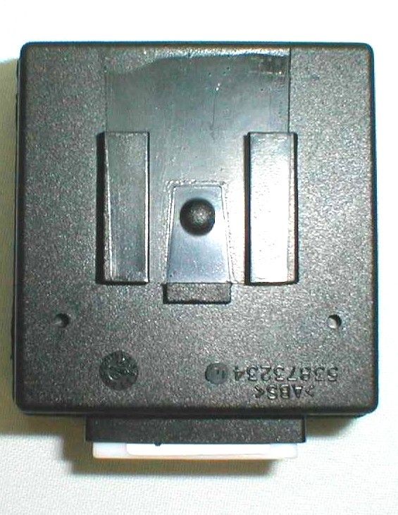
TRW Automotive Electronics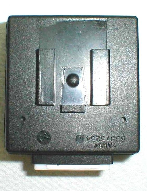
Click to zoom
Application Details
- Equipment Class
- DCD - Part 15 Low Power Transmitter Below 1705 kHz
- Date of Grant
- Jun 19, 2000
- Application Purpose
- Original Equipment
- Date of Application
- Jun 19, 2000
- Equipment Note
- Vehicle Immobilizer System
- Frequency Range
- 0.12500000 - 0.12500000
- Company
- TRW Automotive Electronics
- Country
- United Kingdom
Documents & Files
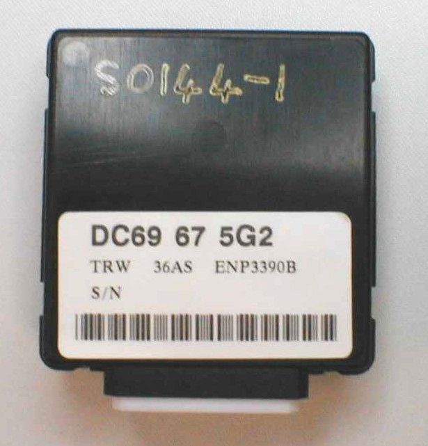
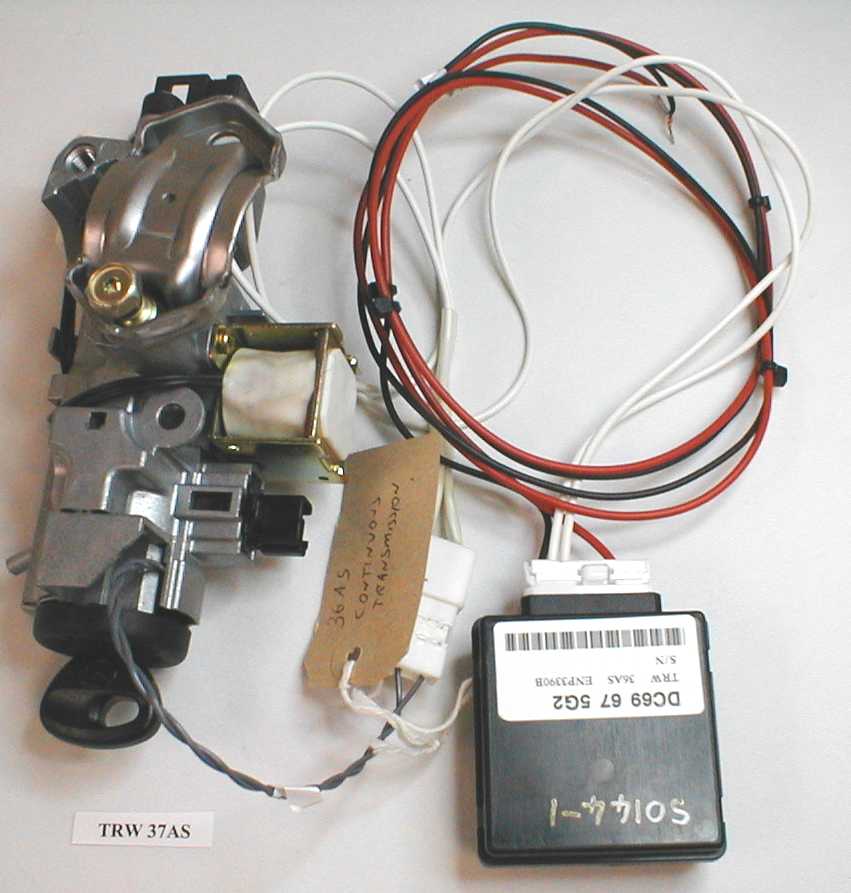
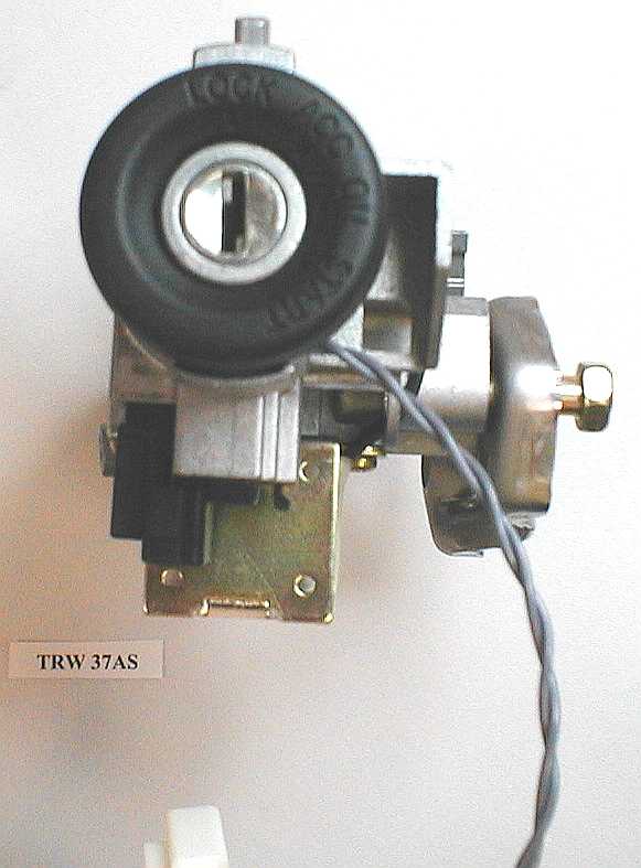
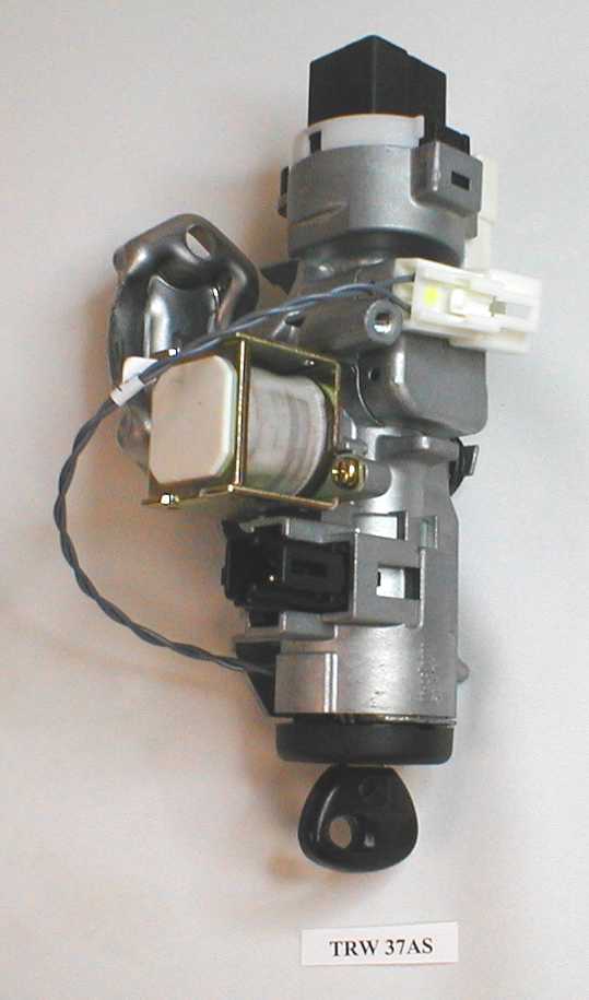
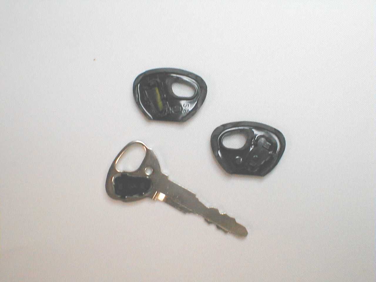
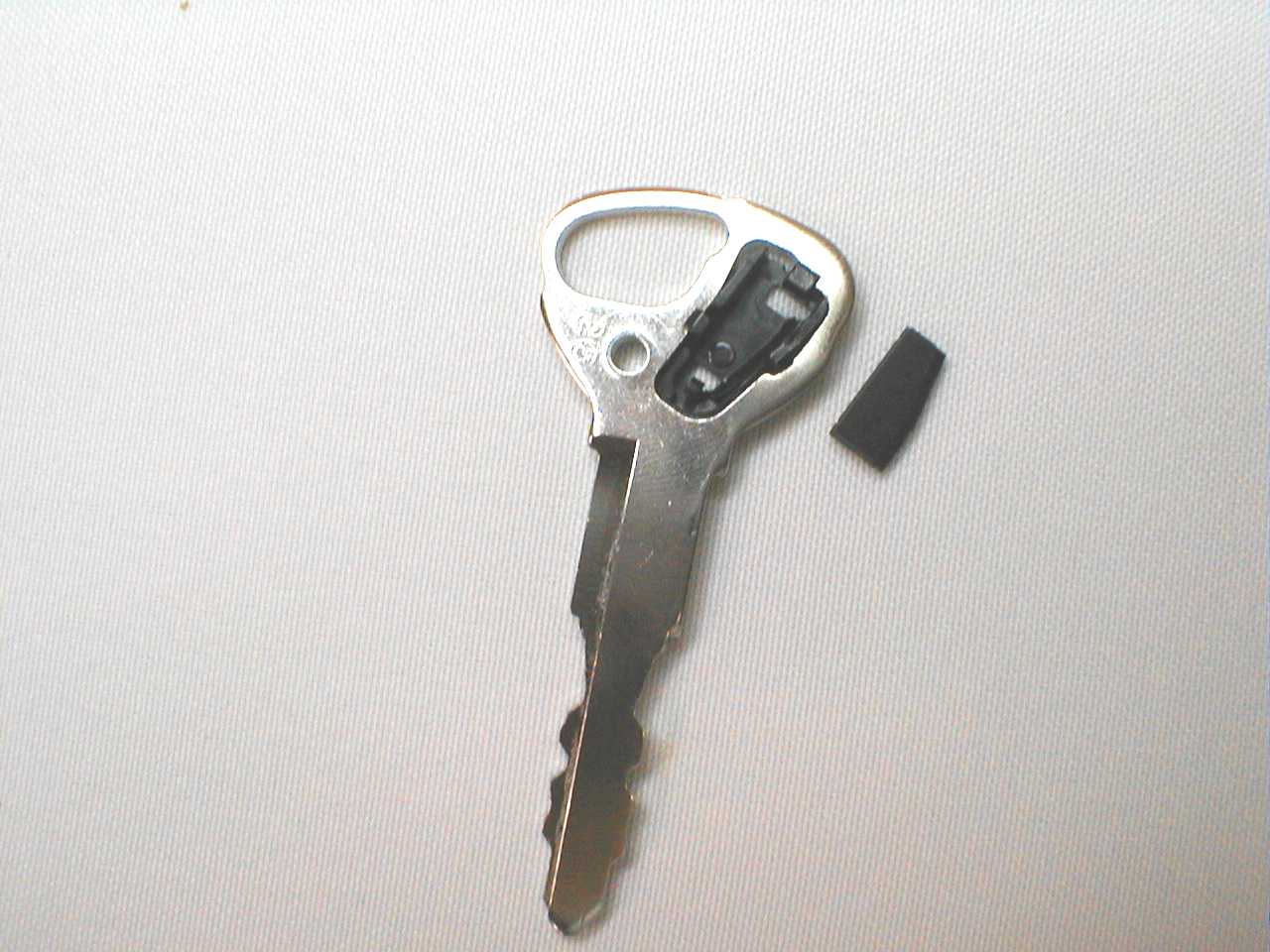
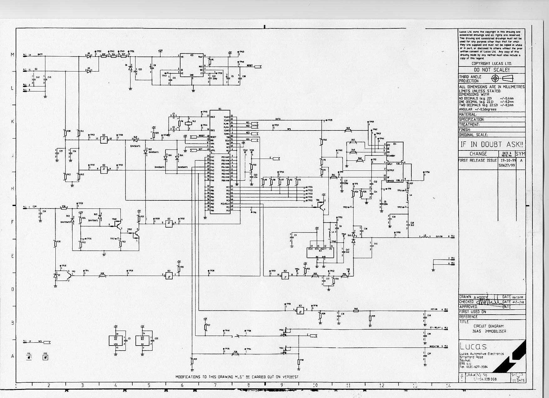
Document Text
Text extracted from the exhibit documents filed with the FCC. Open a document above to read the original.
Users Manual
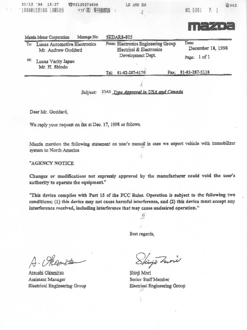
User’s Manual The User’s Manual is not available at this time since the device will be marketed as part of a vehicle. The vehicle manufacturer, Mazda, will include the required notices in their manual when it is published. Please refer to the attached letter from Mazda.
Block Diagram
37AS System Dia gram Ignition Lock Low pass Filter Comparator Oscillator Output buffer Microcontroller (2.0 MHz clock) Serial Interface To Engi ne Ma na ge me nt System Immobiliser Unit (36AS) Transponder (5 TG) Energiser Coil(15EC or 24EC or 25EC) Drivers Mod ulator De modulator Twisted Pair cable Reader IC 125kHz section 2Kb section Ignition Key
ID Label/Location Info
TRW AUTOMOTIVE 37AS IMMOBILISER 125kHz I-ETS 300 330 CEPT SRD 9c GB USA FCC ID: KHH37AS CAN XXXX XXX XXXXX 30 mm 50 mm TYPE APPROVAL LABEL FOR 37AS (other approval numbers to be added when received)
Operational Description
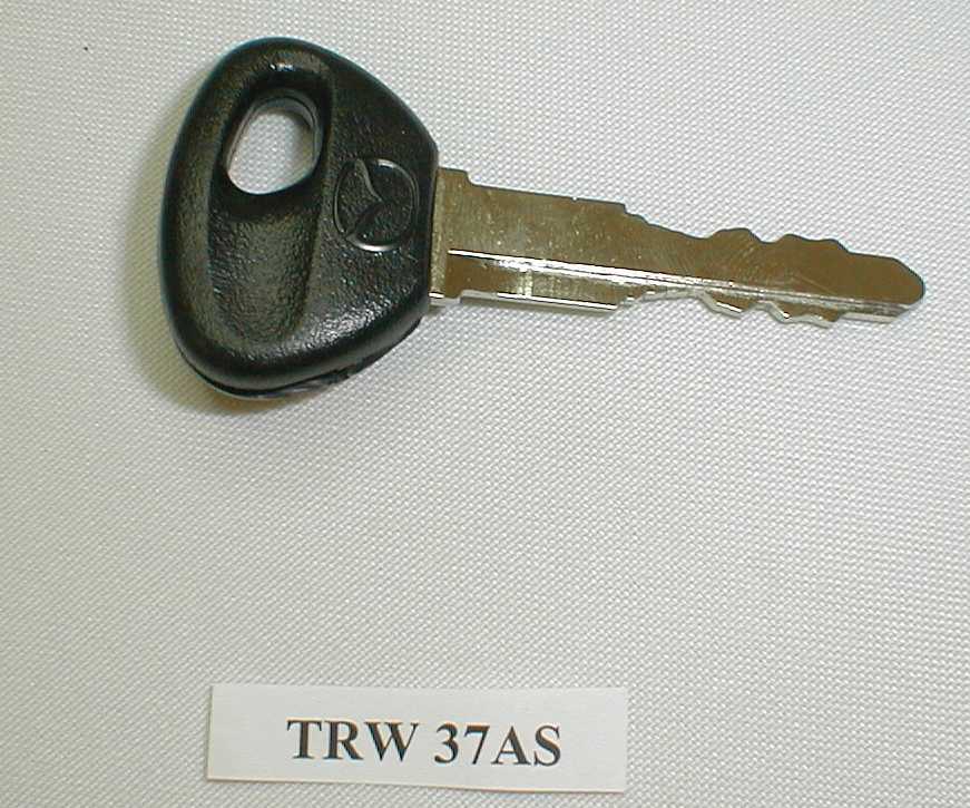
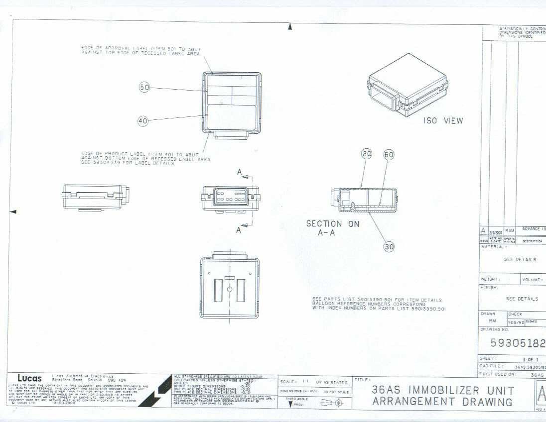
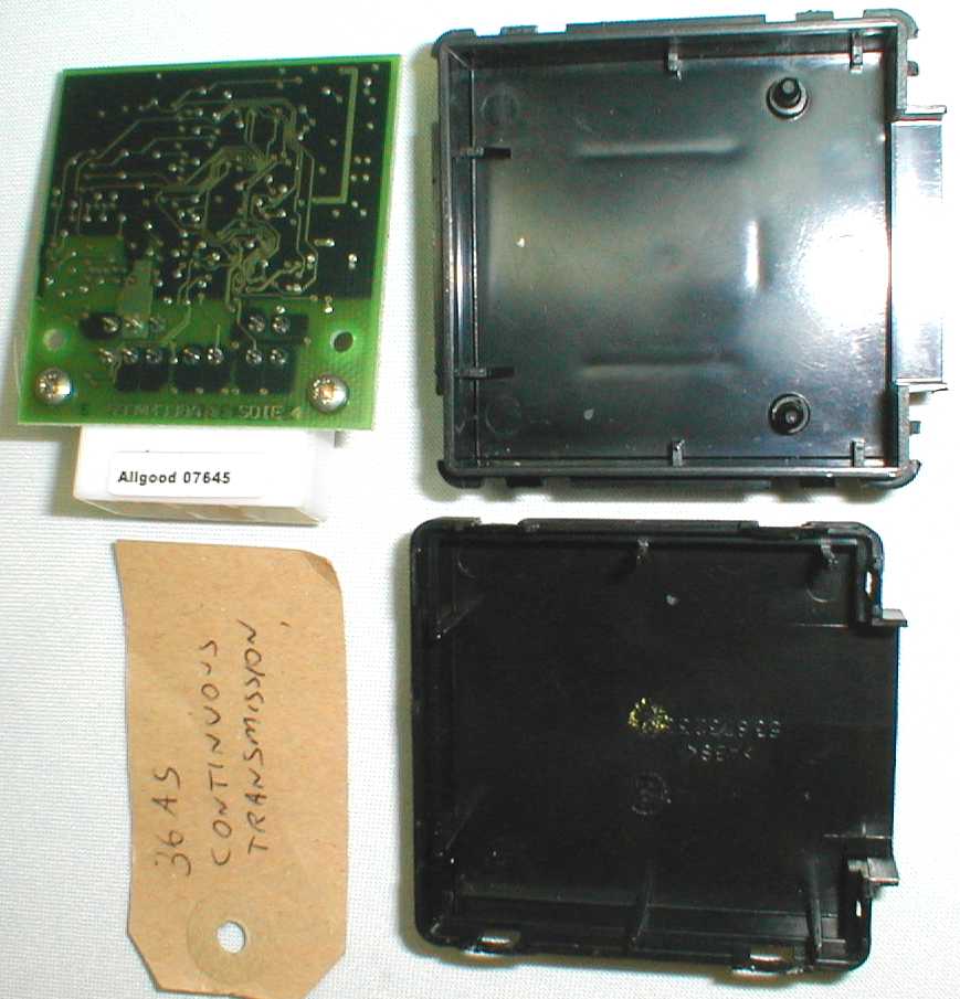
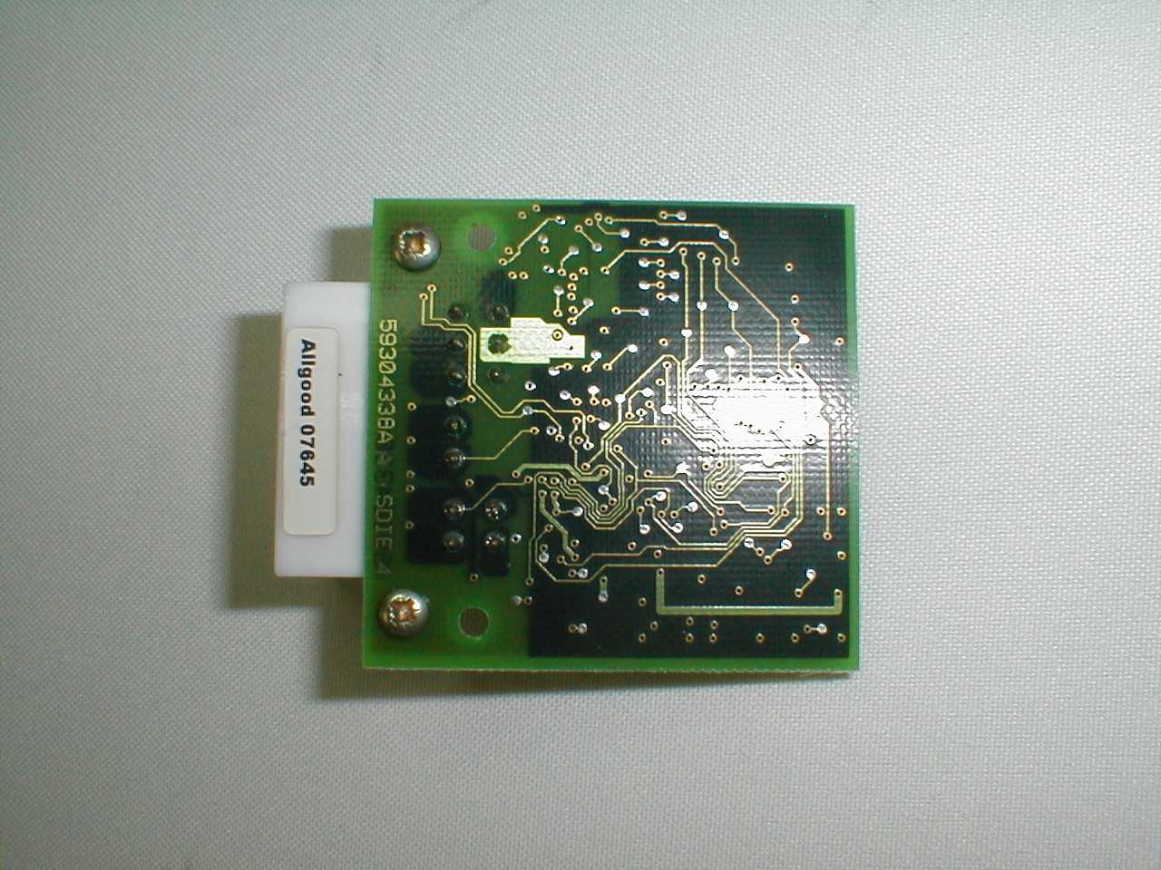
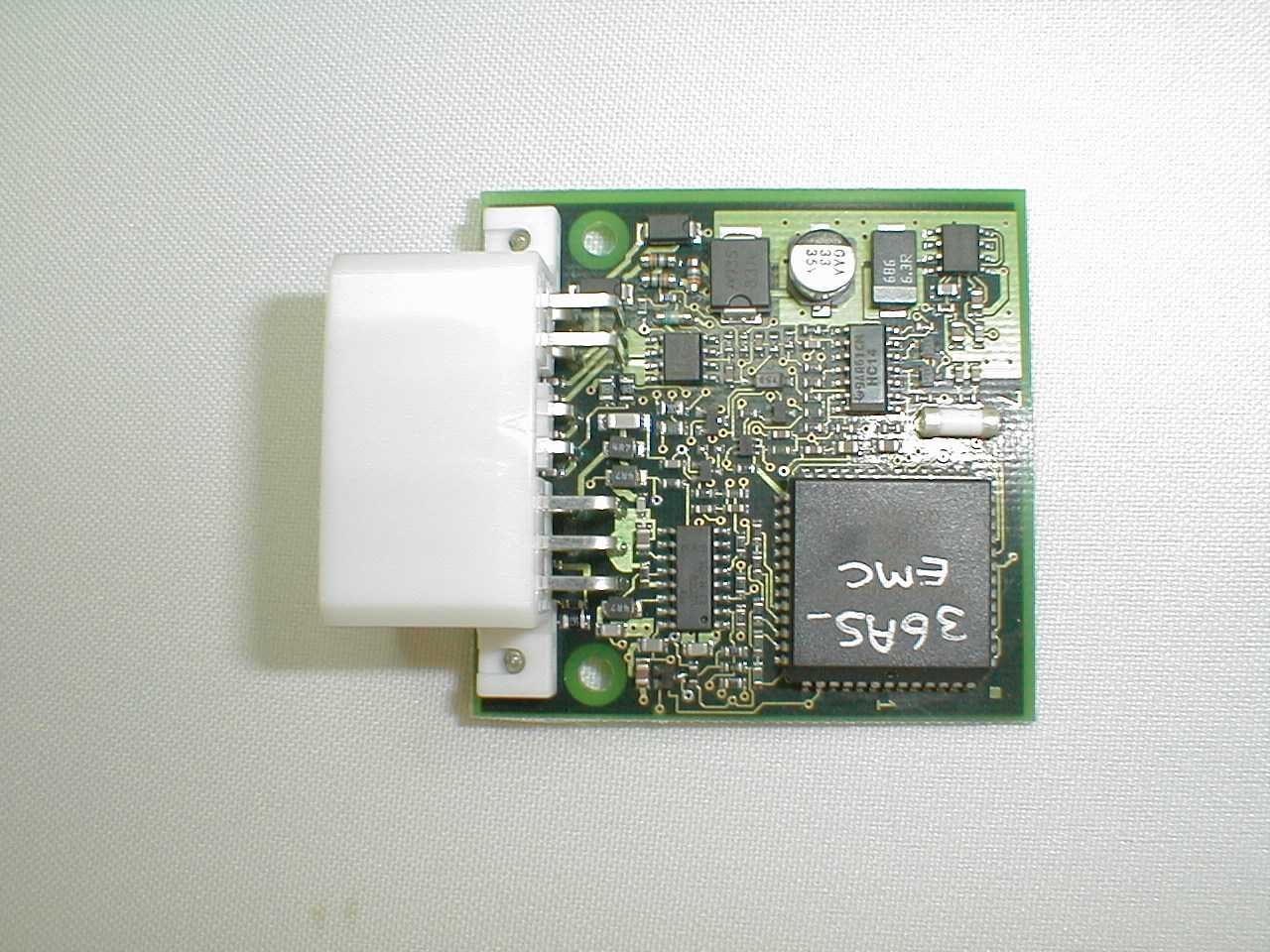
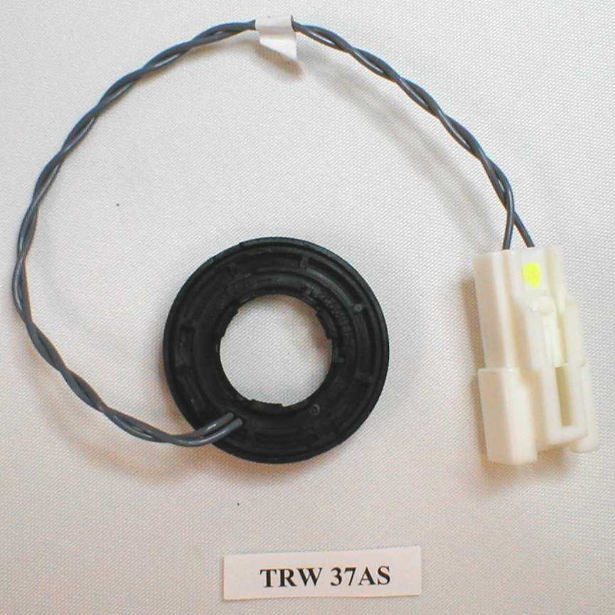
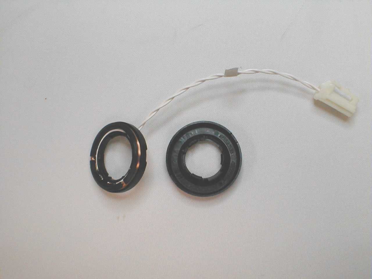
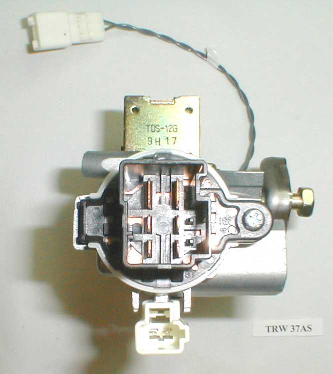
37AS Technical Description Lucas Ltd. 2000Page 1 of 4Printed 10:11 AM 6/20/00 Filename 105707 37AS Technical Description Author: Roger Lee Date: 13 Apr 2000 Filed as: 37AS Tec Description.doc Updated: 13/04/00 15:10 Type Designation: 37AS Declaration of Equipment Characteristics TypeImmobiliser System Frequency Range 125kHz ± 4% Method of Carrier Frequency Generation LC Oscillator Adjacent Channel SeparationN/A Class of Emission14K0W1D Type of ModulationAmplitude Modulation Signal Input LevelN/A Modulation Input ImpedanceN/A Modulation BandwidthN/A Coupling MethodsElectrical Number of Channels1 UtilisationMobile (Permanently installed in vehicle) Duplex operationNo Antenna15EC, 24EC or 25EC (part of 37AS) -all coils variants are electrically identical Alternative AntennaNone Channel SpacingN/A Transmitter Output Power200 x 10 -6 mW Voltage supply range 6V → 15.5V DC Composition of EquipmentSee System Description Temperature RangeCategory 1 (-20 ° C to +55 ° C) Channel SpacingN/A 37AS Technical Description Lucas Ltd. 2000Page 2 of 4Printed 10:11 AM 6/20/00 Filename 105707 System Description The 37AS is a vehicle immobiliser system and has two parts: 1. An immobiliser unit (36AS) 2. An energiser coil The system can have a 15EC, 24EC or 25EC antenna coil. The coils are electrically identical. However, the coils have different ignition key position labels. The energiser coil is fitted to the end of the ignition lock key barrel of the vehicle and the immobiliser unit (36AS) is mounted in the vehicle fascia. The energiser coil is connected to the immobiliser unit by twisted pair wiring. The immobiliser unit is connected to the vehicle battery and the vehicle engine management unit. The immobiliser system communicates with a transponder (5TG) which is mounted in the head of the vehicle ignition key. The system coil will work correctly only when its energiser coil is mounted on an ignition lock key barrel The transponder has no internal power supply and is active only when it is in the electromagnetic field produced by the energiser coil. System Operation When the vehicle is manufactured: 1. The immobiliser unit stores the unique identity codes for each of the vehicle’s transponders in its non-volatile memory 2. The engine management unit stores the identity code for the immobiliser unit in its non-volatile memory When the ignition is turned on, the oscillator in the immobiliser unit drives the energiser coil to produce a 125kHz electromagnetic field which activates the transponder. The transponder and the immobiliser exchange data by modulating the electromagnetic field, the immobiliser uses 100% modulation and the transponder uses <2% modulation. An encrypted “challenge- response” protocol is used to ensure that the exchange of data is secure. The waveforms generated by the 36AS system are discussed on page 4. The engine management system uses a low frequency serial link to request that the immobiliser unit verifies the identity of the transponder and provide its own identity code. If the transponder identity is recognised by the immobiliser and the immobiliser identity is recognised by the engine management unit the engine is allowed to run, otherwise the engine is stopped. 37AS Technical Description Lucas Ltd. 2000 Page 3 of 4 Printed 10:11 20 Jun 2000 Filename 105707 37AS System Dia gram Ignition Lock Low pass Filter Comparator Oscillator Output buffer Microcontroller (2.0 MHz clock) Serial Interface To Engine Management System Immobiliser Unit (36AS) Transponder (5TG) Energiser Coil(15EC or 24EC or25EC) Drivers Modulator Demodulator Twisted Pair cable Reader IC 125kHz section 2Kb section Ignition Key 37AS Technical Description Lucas Ltd. 2000Page 4 of 4Printed 10:11 20 Jun 2000 Filename 105707 37AS Output Waveform The field observed in the energiser coil goes through four stages: Power, ID, Challenge and Response. Power Stage When the vehicle ignition is turned on, the coil generates a cw signal which powers the transponder. This stage lasts 5 to 10 ms. ID Stage The transponder then transmits a 64-bit identifying code (ID) at 2 kbits per second by imposing a small (~ 2%) amplitude modulation on to the cw signal generated by the coil. The ID code is repeated for, typically, 80 ms until the immobiliser enters the Challenge mode (see next paragraph). The waveform during the ID stage is: Challenge Stage The immobiliser interprets the ID code from the transponder and, when the code is recognised, generates a 100% amplitude modulated signal in the coil, the modulating signal representing a 66-bit challenge code. Pulses representing a ‘0’ are ~ 150μs long and those representing a ‘1’ are ~ 400μs long. The gaps between spaces are ~ 150μs long. The Challenge stage waveform is: Response Stage The coil then returns to cw mode and the transponder imposes a small amplitude modulated signal representing a response. The response consists of a ‘stand-by’ code, which the transponder generates while it is analysing the challenge code it has received, and a 32-bit response code, which is repeated for, typically, 50 ms until the response is recognised by the immobiliser. The waveform generated during the Response stage is similar to that for the ID stage. If the vehicle immobiliser considers that the communications with the transponder are satisfactory, the vehicle engine is allowed to run. If a valid response is not received by the immobiliser within approximately 300 ms, the immobiliser considers the transponder to be invalid and the engine is stopped. 1 0101101 0010100 > 64 clocks
Test Report
FCC CERTIFICATION TEST REPORT for TRW Automotive Electronics Phoenix Way Cirencester Gloucestershire GL7 1QG United Kingdom FCC ID: KHH37AS June 9, 2000 WLL PROJECT #: 5828X This report may not be reproduced, except in full, without the prior written consent of Washington Laboratories, Ltd. TRW Automotive Electronics FCC ID: KHH37AS WLL Project # 5828X i TABLE OF CONTENTS Statement of Qualifications ____________________________________________________ 1.0 INTRODUCTION...............................................................................................................................................................4 1.1 SUMMARY........................................................................................................................................................................4 2.0 DESCRIPTION OF EQUIPMENT UNDER TEST (EUT)..............................................................................................4 2.1 ON-BOARD OSCILLATORS.............................................................................................................................................5 3.0 TEST CONFIGURATION.................................................................................................................................................5 3.1 TESTING ALGORITHM...................................................................................................................................................5 3.2 CONDUCTED EMISSIONS TESTING...............................................................................................................................5 3.3RADIATED EMISSIONS TESTING...................................................................................................................................5 3.3.1Radiated Data Reduction and Reporting.............................................................................................................6 TABLES Table 1.Radiated Emissions Results Table 2.System Under Test Table 3.Measurement Equipment Used EXHIBITS Exhibit 1.Bandwidth Plot APPENDICES Appendix A.Statement of Measurement Uncertainty TRW Automotive Electronics FCC ID: KHH37AS WLL Project # 5828X TRW Automotive Electronics FCC ID: KHH37AS WLL Project # 5828X 4 of 12 FCC CERTIFICATION TEST REPORT for FCC ID: KHH37AS 1.0 Introduction This report has been prepared on behalf of TRW Automotive Electronics to support the attached Application for Equipment Authorization. The test and application are submitted for an Intentional Radiator under Part 15.209 of the FCC Rules and Regulations. The Equipment Under Test was the TRW Automotive Electronics Low Power Transceiver. All measurements herein were performed according to the 1992 version of ANSI C63.4. The measurement equipment conforms to ANSI C63.2 Specifications for Electromagnetic Noise and field Strength Instrumentation. Calibration checks are made periodically to verify proper performance of the measuring instrumentation. All measurements are performed at Washington Laboratories, Ltd. test center in Gaithersburg, MD. Site description and site attenuation data have been placed on file with the FCC's Sampling and Measurements Branch at the FCC laboratory in Columbia, MD. Washington Laboratories, LTD. has been accepted by the FCC and approved by NIST NVLAP (NVLAP Lab Code: 200066-0) as an independent FCC test laboratory. All results reported herein relate only to the equipment tested. The measurement uncertainty of the data contained herein is ±2.3 dB. Refer to Appendix A for Statement of Measurement Uncertainty. This report shall not be used to claim product endorsement by NVLAP or any agency of the US Government. 1.1 Summary The TRW Automotive Electronics AS37 Immobiliser System complies with the limits for an Intentional Radiator under Section 15.209. 2.0 Description of Equipment Under Test (EUT) The TRW Automotive Electronics 37AS Immobiliser System is a 125 kHz low power transceiver that is used as a theft deterrent ignition system switch used in automobiles. The 37AS consists of an energizer coil (15EC) and an immobilizer unit (36AS). The energizer coil is fitted to the end of the ignition lock key barrel of the vehicle and the immobilizer unit is mounted in the vehicle fascia. The energizer coil is connected to the immobilizer unit via twisted pair wiring. The immobilizer communicates with a transponder (5TG) that is mounted in the handle of the vehicle ignition key. With the ignition turned on, the oscillator in the immobilizer unit drives the energizer coil to produce a 125 kHz electromagnetic field that activates the transponder. The transponder and immobilizer exchange data and if a) the transponder identity is recognized by the immobilizer and, b) the immobilizer identity is recognized by the engine management unit, the engine is allowed to run. If recognition does not occur, the engine is immobilized, or not allowed to run. TRW Automotive Electronics FCC ID: KHH37AS WLL Project # 5828X 5 of 12 2.1 On-board Oscillators The TRW Automotive Electronics 37AS Immobilizer System contains a 2 MHz oscillator and a single chip transceiver which uses an inductor and capacitor to provide a 125 kHz resonant circuit. 3.0 Test Configuration To complete the test configuration required by the FCC, the 37AS Immobilizer transceiver was mounted on a vehicle ignition key barrel and a key was placed in the ignition to modulate the carrier. The ignition barrel was placed in the horizontal plane in order to simulate “normal” installation in a vehicle. Unshielded wires were connected to the unit to simulate connection to the vehicle wiring. During emissions testing, 14.4 VDC was applied via a bench power supply to simulate a car vehicle battery with a key installed into the switch. 3.1 Testing Algorithm The transceiver was turned on and modulated by the transponder in the key. Worst case emissions are recorded in the data tables. 3.2 Conducted Emissions Testing Conducted emissions testing were …
Text truncated - open the document above for the full version.
Contact Information
Applicant
Roger Lee(Approvals Engineer)
01285 657981Fax: 01285 658258
Technical Contact
Washington Laboratories, Ltd.Greg Snyder
[email protected]301 477 0220
7560 Lindbergh Dr · Gaithersburg, Maryland · United States
Non-Technical Contact
Washington Laboratories, Ltd.Greg Snyder
[email protected]301 477 0220
Test Firm
Washington Laboratories, Ltd.Michael Violette
Technical Specifications
| # | Rule Parts | Frequency Range | Power Output |
|---|---|---|---|
| 1 | 15C | 0.125 MHz - 0.125 MHz | - |
Other Applications from TRW Automotive Electronics
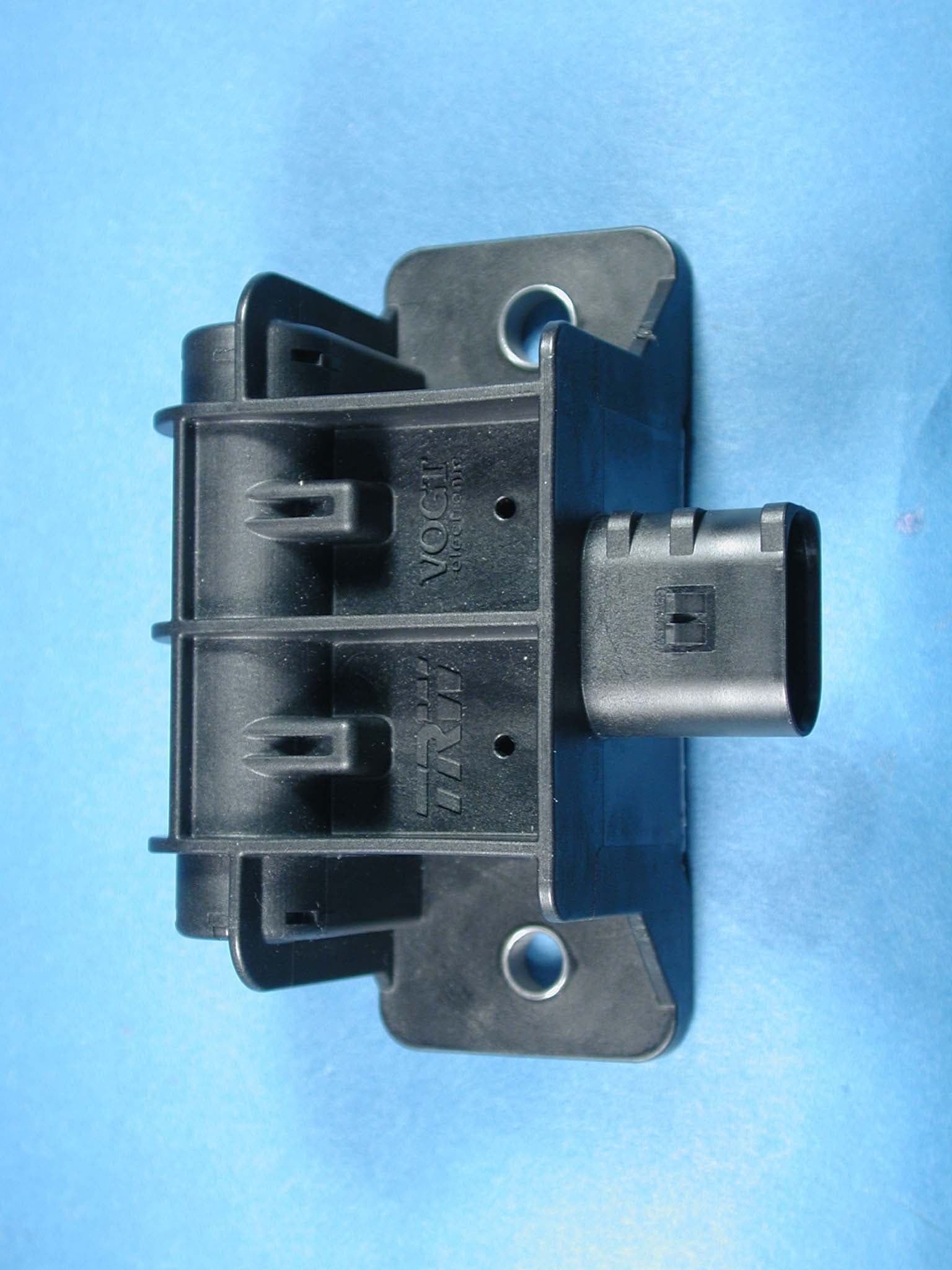
KHH29EC
Jul 05, 2004Transmitter/Initiator
Equipment Class
DCD - Part 15 Low Power Transmitter Below 1705 kHz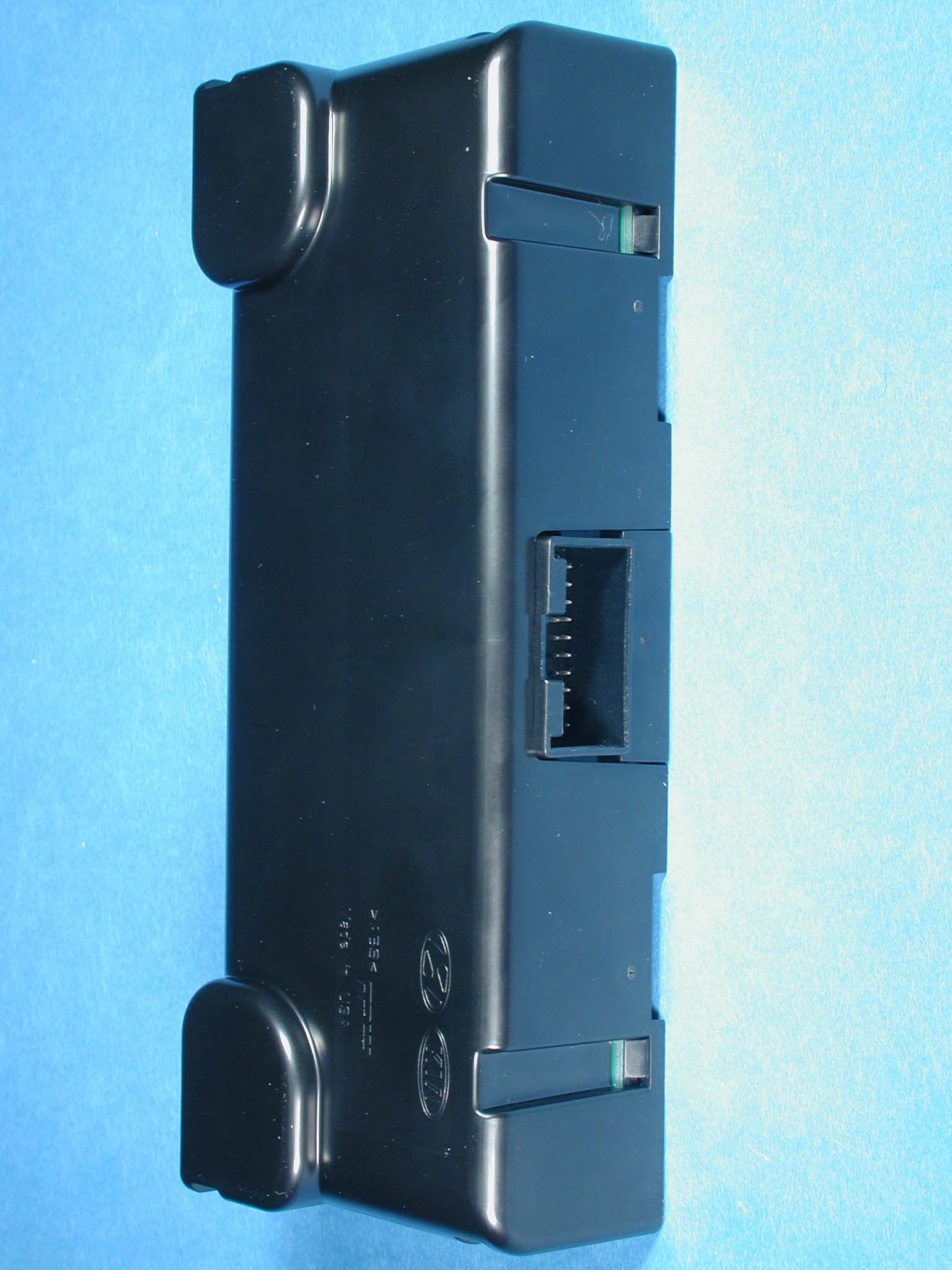
KHH14RC
Jul 05, 2004Receiver
Equipment Class
CYY - Communications Receiver used w/Pt 15 Transmitter
KHH20TN-1
Mar 21, 2000Remote Control Transmitter
Equipment Class
DSC - Part 15 Security/Remote Control Transmitter
KHH17TN
Sep 28, 1999DSC - Part 15 Security/Remote Control Transmitter
Equipment Class
DSC - Part 15 Security/Remote Control Transmitter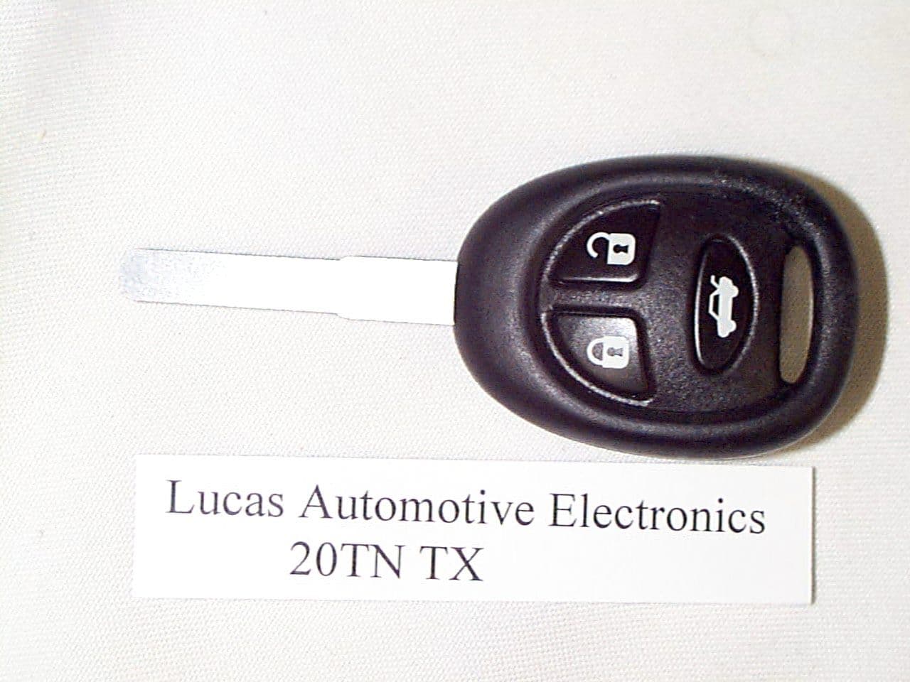
KHH20TN
Aug 23, 1999DSC - Part 15 Security/Remote Control Transmitter
Equipment Class
DSC - Part 15 Security/Remote Control Transmitter