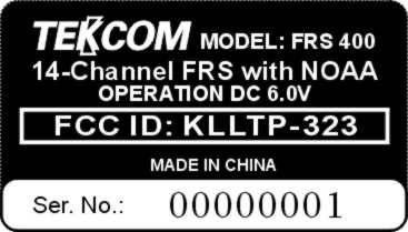
KLLTP-323Family Radio Transceiver
Tekcom Industries Limited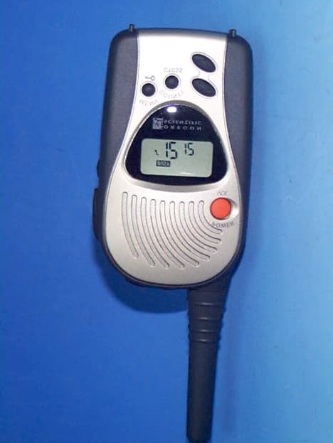
Click to zoom
Application Details
- Equipment Class
- FRF - Part 95 Family Radio Face Held Transmitter
- Date of Grant
- Sep 20, 2001
- Application Purpose
- Original Equipment
- Date of Application
- Jul 24, 2001
- Equipment Note
- Family Radio Transceiver
- Frequency Range
- 462.56250000 - 467.71250000
- Company
- Tekcom Industries Limited
- Country
- Hong Kong
Documents & Files
Document Text
Text extracted from the exhibit documents filed with the FCC. Open a document above to read the original.
Users Manual
1 OWNER’S MANUAL FRS RADIO WRF 108 INTRODUCTION Your FRS radio is a portable, easy-to-use, two-way radio with clock and NOAA receiver that you can carry almost anywhere. It makes you can contact others as well as watching NOAA WX broadcasts in one unit meanwhile grasping time. Use it at shopping malls, amusement parks, sports events, or at the beach to contact family and friends, or for vital communications in a neighborhood watch. Your radio has 14 channels and 38 different quiet codes. If someone else is using the channel you selected and you do not want to hear that person, select another channel or use the quiet feature. You can talk with a person who has a FRS radio if both radios are tuned to the same channel and quiet code. Your radio has auto-squelch (FRS only), which means you will not hear anything on a channel unless someone is transmitting nearby on the same channel. You can turn off auto-squelch to hear weaker, distant transmissions. Also, if the radio is idle for a period of time of 2 hours, it automatically shuts off. It turns on again when you press POWER/VOL key for 2 seconds. You can connect an optional earphone/microphone and a charger (not supplied) to the radio. And, the belt clip lets you take your radio almost anywhere. FCC INFORMATION Important: Do not open your radio to make any internal adjustments. Your radio is set up to transmit a regulated signal on one of 14 assigned frequencies. It is against the law to alter or adjust the settings inside the radio to exceed those limitations. Any adjustments to your radio must be made by a qualified technician using the proper test equipment. To be safe and sure: ! Never open your radio’s case. ! Never change or replace anything in your radio except the batteries. Your radio might cause TV or radio interference even when it is operating properly. To determine whether your radio is causing the interference, turn it off. If the interference goes away, your radio is causing it. Try to eliminate the interference by: 2 ! moving your radio away from the receiver ! calling your local service store for help If you cannot eliminate the interference, the FCC requires that you stop using the radio. This device complies with Part 15 of the FCC Rules. Operation is subject to the following two conditions: (1) This device may not cause harmful interference, and (2) this device must accept any interference received, including interference that may cause undesired operation. SAFETY INFORMATION Your wireless hand-held portable transceiver contains a low power transmitter. W hen the Push-to-Talk button is pushed it sends out radio frequency (RF) signals. The device is authorized to operate at a duty factor not to exceed 50%. In August 1996, the Federal Communications Commission (FCC) adopted RF exposure guidelines with safety levels for hand-held wireless devices. CAUTION: To maintain compliance with the FCC’s RF exposure guidelines, hold the transmitter and antenna at least 2 inch (5 centimeters) from your face and speak in normal voice, with the antenna pointed up and away from the face. If you wear the handset on your body while using the headset accessory, use only the supplied belt clip for this product and when transmitting, take it out of the belt to ensure that the antenna is at least 1 inch (2.5 centimeters) from you body. Use only the supplied antenna. Unauthorized antennas, modifications, or attachments could damage the transmitter and may violate FCC regulations. 3 USING THE RADIO A. DISPLAY Your radio comes with a multifunction-backlighted display. In clock mode before turning on your radio, pressing MONI/FUNC/NOAA or POW ER/VOL button can illuminate the backlit for 7 seconds; in working mode, By pressing any button except the PTT, the backlight will illuminate for 7 seconds. 1. Shows the selected channel number. 2. Shows the selected privacy code number. 3. Shows the selected county code for NOAA. 4. “ COUNTY ”: Displays when your radio is in county code entering mode. 5. “ BUSY ”: Displays when a call is being received. 6. “ TX ”: Displays when your radio is transmitting or the PTT button is pressed. 7. “ FUNC ”: Displays when the secondary function is enabled. 8. “ SC ”: Displays when the scan mode is activated. 9. Shows the sequence number of the county your entered or the pertinent NOAA frequency code. 10. “ ”: The icon flashing Indicates the batteries are low. Replace the batteries when it appears. 11. “ ”: Displays when the key tone function is activated. 12. “ ”: Displays when the keypad lock is activated. 13. “ C-TONE ”: Displays when the courtesy tone function is activated. 4 14. “ VOX L ”: Displays when VOX function is set to be low. 15. “ VOX H ”: Displays when VOX function is set to be high. 16. “ INT ”: Displays when intercom function is enabled. (Assume the intercom accessories are used.) 17. “ NOAA ”: Displays when your radio is in NOAA ON position. 18. “ “: Displays when your radio stands by in NOAA mode. 19. “ “: Displays when your radio is mute in NOAA mode. 20. “ ((WARNING)) (WATCH) STATEMENT ”: Displays when an alert signal is received during your radios’s in NOAA mode. B. FUNCTION AND LOCATION OF THE CONTROLS 1 1 . . POWER/VOL Button 2 2 . . UP Button 3 3 . . DOWN Button 4 4 . . COUNTY/CTCSS Button 5 5 . . MENU/KEYLOCK Button 6 6 . . MONI/FUNC/NOAA Button 7 7 . . PTT (Push To Talk) Button 8 8 . . External Speaker/Microphone Jack 9 9 . . Charger Jack 5 1 1 0 0 . . Battery Compartment C. FUNCTION AND OPERATION OF THE FRS RADIO Preparation Your radio uses four AAA batteries for power supply. W e recommend alkaline batteries. However, you can use rechargeable batteries in the radio. To start using your radio, insert four AAA batteries into the battery compartment, noting the polarities. As soon as you connect the power, the unit will enter the clock mode and the cleared time will display on LCD. Note: Once your batteries are used up, you should replace all the four alkaline batteries with new ones. Then the cl…
Text truncated - open the document above for the full version.
External Photos
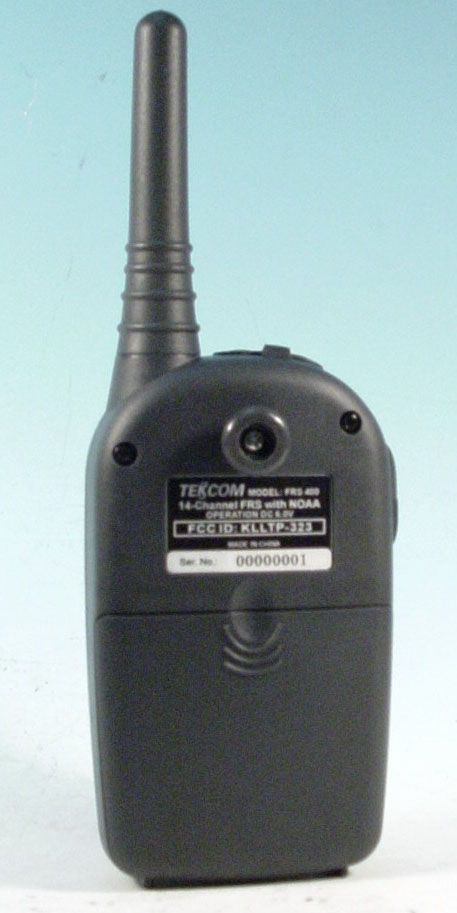
Front View Back View
Operational Description
ALIGNMENT PROCEDURES Important: The FCC requires that any frequency adjustme nt on a radiophone must be do ne by authorized person, who is the holder of a current first or second class radiotelephone license. This unit has been fully aligned at the factory before shipment and does not normally require furt her adjust ment. W hen necessary, however, the unit may be aligned as indicated below. Do not adjust any circuit in this radiotelephone unless you understand the circuit operation and have experience of adjusting radiotelephone. Tampering with the radiotelephone may upset the alignment and lower its performance. Test Equipment Required: Regulated DC power supply, 0~12V, 1A or higher; or 8.4V, 1A Audio signal generator, 10Hz~2KHz Digital multi meter Deviation meter Frequency counter, 0~500MHz high impedance Oscilloscope RF power meter, 5W High frequency standard generator,>160MHz Tracking generator, >160MHz Distortion analyzer Audio level meter T-coupler Aligning drivers, etc.
Schematics
5
Test Report
ENGINEERING STATEMENT For Type Certification of Tekcom Industries Limited Model No: TP-323 FCC ID: KLLTP-323 I am an Electronics Engineer, a principal in the firm of Hyak Laboratories, Inc., Springfield, Virginia. My education and experience are a matter of record with the Federal Communications Commission. Hyak Laboratories, Inc. has been authorized by Tekcom Industries, Ltd., to make type certification measurements on the TP-323 transceiver. These tests made by me or under my supervision in our Springfield laboratory. Test data and documentation required by the FCC for Type Certification are included in this report. The data verifies that the above mentioned transceiver meets FCC requirements and Type Certification is requested. ______________________________ Rowland S. Johnson Dated: July 17, 2001 A. INTRODUCTION The following data are submitted in connection with this request for type certification of the TP-323 transceiver in accordance with Part 2, Subpart J of the FCC Rules. The TP-323 is a portable, battery operated, UHF, frequency modulated transceiver intended for 12.5 kHz channel family radio service applications in the 462.5625-467.7125 MHz band. It operates from a nominal 6.0 Vdc battery supply. MFR rated output power is 0.5 watts ERP(d). B. GENERAL INFORMATION REQUIRED FOR TYPE CERTIFICATION (Paragraph 2.983 of the Rules) 1. Name of applicant: Tekcom Industries, Ltd. 2. Identification of equipment: FCC ID: KLLTP-323 a. The equipment identification label is submitted as a separate exhibit. b. Photographs of the equipment are submitted as a separate exhibit. 3. Quantity production is planned. 4. Technical description: a. 11k0F3E emission b. Frequency range: 462.5625 - 467.7125 MHz. c. Operating power of transmitter is fixed at the factory at less than 0.5 W ERP(d). d. Maximum power permitted is 0.5 watts, and the TP-323 fully complied with that power limitation. e. The dc voltage and dc currents at final amplifier: Collector voltage: 5.9 Vdc Collector current: 0.29 A f. Function of each active semiconductor device: See Appendix 1. g. Complete schematic diagram is submitted as a separate exhibit. h. A draft instruction manual is submitted as a separate exhibit. i. The transmitter tune-up procedure is submitted as a separate exhibit. 2 B. GENERAL INFORMATION (continued) j. A description of circuits for stabilizing frequency is included in Appendix 2. k. A description of circuits and devices employed for suppression of spurious radiation and for limiting modulation is included in Appendix 3. l. Not applicable. 5. Data for 2.985 through 2.997 follow this section. C. RF Power Output (Paragraph 2.985(a) of the Rules) The TP-323 has a permanently attached built-in antenna without provisions for a coaxial connector. Therefore RF power output was measured by substitution. The transmitter was tuned by the factory. TABLE 1 Operating Freq., MHz Power watts into a dipole antenna 462.5625 0.49 D. MODULATION CHARACTERISTICS 1. A curve showing frequency response of the transmitter is shown in Figure 1. Reference level was audio signal output from a Boonton 8220 modulation meter with one kHz deviation. Audio output was measured with an Audio Precision System One integrated test system. 2. Modulation limiting curves are shown in Figure 2, using a Boonton 8220 modulation meter. Signal level was established with a Audio Precision System One integrated test system. The curves show compliance with paragraphs 2.987(b). 3. Figure 3 is a graph of the post-limiter low pass filter which provides a roll-off of 60Logf/3 dB where f is audio frequency in kHz. Measurements were made following EIA RS-152B with an Audio Precision System One integrated test system on the Boonton 8220 modulation meter audio output. 3 4. Occupied Bandwidth (Paragraphs 2.989(c) of the Rules) Figure 4 is a plot of the sideband envelope of the transmitter output taken with a Tektronix 494P spectrum analyzer. Modulation corresponded to conditions of 2.989(c)(1) and consisted of 2500 Hz tone at an input level 16 dB greater than that necessary to produce 50% modulation at 2895 Hz, the frequency of maximum response. Emission designator: (2M + 2D) (2 x 3 kHz) + (2 x 2.5 kHz) = 11k0F3E 4 FIGURE 1 MODULATION FREQUENCY RESPONSE MODULATION FREQUENCY RESPONSE FCC ID: KLLTP-323 FIGURE 1 5 FIGURE 2 AUDIO LIMITER CHARACTERISTICS AUDIO LIMITER CHARACTERISTICS FCC ID: KLLTP-323 FIGURE 2 6 FIGURE 3 AUDIO LOW PASS FILTER RESPONSE AUDIO LOW PASS FILTER RESPONSE FCC ID: KLLTP-323 FIGURE 3 7 FIGURE 4 OCCUPIED BANDWIDTH ATTENUATION IN dB BELOW MEAN OUTPUT POWER Required On any frequency more than 50% up to and including 100% of the 25 authorized bandwidth, 12.5 kHz (6.25-12.5 kHz) On any frequency more than 100%, up to and including 250% of the 35 authorized bandwidth (12.5-31.25 kHz) On any frequency removed from the assigned frequency by more 43+10LogP = 40 than 250% of the authorized (P = 0.49) bandwidth (over 31.25 kHz) OCCUPIED BANDWIDTH FCC ID: KLLTP-323 FIGURE 4 8 D. MODULATION CHARACTERISTICS (Continued) The plots are within FCC limits. The horizontal scale frequency) is 10 kHz per division and the vertical scale amplitude) is a logarithmic presentation equal to 10 dB per division. E. SPURIOUS EMISSIONS AT THE ANTENNA TERMINALS (Paragraph 2.991 of the Rules) The TP-323 has a permanently attached antenna. There is no connector for an external antenna. Therefore, no antenna terminal conducted measurements were made. F. DESCRIPTION OF RADIATED SPURIOUS MEASUREMENT FACILITIES A description of the Hyak Laboratories’ radiation test facility is a matter of record with the FCC. The facility was accepted for radiation measurements from 25 to 1000 MHz on October 1, 1976 and is currently listed as an accepted site. G. FIELD STRENGTH MEASUREMENTS OF SPURIOUS RADIATION Field intensity measurements of radiated spurious emissions from the TP-323 were made by substitution with a Tektronix 494P spectrum analyzer using Singer DM-105 for the measurements to 1 GHz…
Text truncated - open the document above for the full version.
Contact Information
Applicant
Arthur Kwan(Managing Director)
886 2 609-1822Fax: 886 2 601-9389
Technical Contact
Hyak Laboratories, Inc.Rowland S Johnson
[email protected](703) 451-1188
7011 Calamo St., Suite 107 · Springfield, Virginia · United States
Non-Technical Contact
Hyak Laboratories, Inc.Georgia Hall
[email protected](703) 451-1188
Test Firm
Hyak Laboratories, Inc.Rowland Johnson
703-451-1188
Technical Specifications
| # | Rule Parts | Frequency Range | Power Output | Emission | Tolerance |
|---|---|---|---|---|---|
| 1 | 95 | 462.5625 MHz - 467.7125 MHz | 490.00 mW | 11K0F3E | 0.0002500000 % |
Other Applications from Tekcom Industries Limited

KLLTM-886
Nov 13, 2005Handheld Marine Transceiver
Equipment Class
GHH - Part 80 VHF Hand Held Transmitter (GMDSS)
KLLTM-366
Nov 07, 2005MARINE TRANSCEIVER
Equipment Class
TNB - Licensed Non-Broadcast Station Transmitter
KLLTP-329
Apr 14, 200414 CH FRS TRANSCEIVER
Equipment Class
FRF - Part 95 Family Radio Face Held Transmitter
KLLTM-882
Aug 04, 2003VHF Marine Handheld Transceiver
Equipment Class
GVH - Part 80 VHF Transmitter (GMDSS)
KLL2101904
Jun 12, 200322CH FRS/ GMRS Transceiver
Equipment Class
FRF - Part 95 Family Radio Face Held Transmitter