KUJCE10006Ceiling Fan Remote Controller (Transmitter)
Chungear Industrial Co Ltd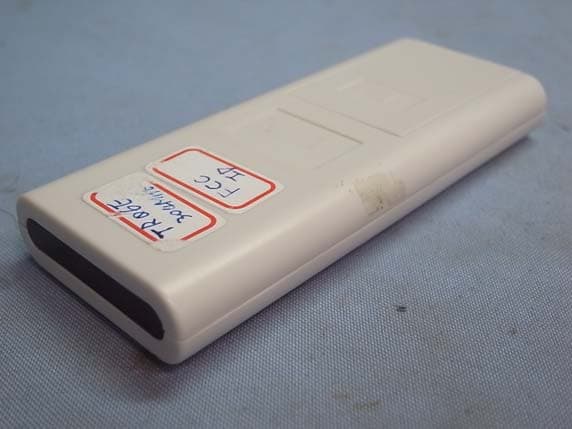
Click to zoom
Application Details
- Equipment Class
- DSC - Part 15 Security/Remote Control Transmitter
- Date of Grant
- Nov 24, 2011
- Application Purpose
- Original Equipment
- Date of Application
- Nov 24, 2011
- Equipment Note
- Ceiling Fan Remote Controller (Transmitter)
- Frequency Range
- 304.00000000 - 304.00000000
- Company
- Chungear Industrial Co Ltd
- Country
- Taiwan
Documents & Files
Document Text
Text extracted from the exhibit documents filed with the FCC. Open a document above to read the original.
Users Manual
Antenna Fig. 1 CEILING FAN & LIGHT REMOTE CEILING FAN & LIGHT REMOTE OPERATION AND INSTALLATION INSTRUCTIONS OPERATION AND INSTALLATION INSTRUCTIONS IMPORTANT SAFETY INSTRUCTIONS IMPORTANT SAFETY INSTRUCTIONS 1. Read and keep this instruction sheet carefully. 1. Read and keep this instruction sheet carefully. 2. Please note that all fixed wiring appliances should be installed by a qualified electrician. 2. Please note that all fixed wiring appliances should be installed by a qualified electrician. 3. The supply to the receiver shoul d be connected on its own circuit. 3. The supply to the receiver shoul d be connected on its own circuit. 4. Switch off the power at main power box before working on receiver or ceiling fan. 4. Switch off the power at main power box before working on receiver or ceiling fan. 5. Install receiver into the canopy of ceiling fan per Fig’s 1 and 2. 5. Install receiver into the canopy of ceiling fan per Fig’s 1 and 2. 6. This unit is to be used for the control of ceiling f an and its electrical source must be AC 110/120V, 60Hz. 6. This unit is to be used for the control of ceiling f an and its electrical source must be AC 110/120V, 60Hz. 7. Do not install in damp location or immerse into water. (For indoor use only) 7. Do not install in damp location or immerse into water. (For indoor use only) 8. Do not drop or bump the unit. 8. Do not drop or bump the unit. 9. Do not use with solid state ceiling fans. 9. Do not use with solid state ceiling fans. 10. CAUTION: To reduce the risk of fire or injury, do not use this produ ct in conjunction with any variable (rheostat) wall control. 10. CAUTION: To reduce the risk of fire or injury, do not use this produ ct in conjunction with any variable (rheostat) wall control. INSTALLATION INSTRUCTIONS INSTALLATION INSTRUCTIONS 1. After switching power off, remove ceiling fan canopy from the mounting bracket. Disconnect existing wiring between ceiling fan and supply at electrical junction box . 1. After switching power off, remove ceiling fan canopy from the mounting bracket. Disconnect existing wiring between ceiling fan and supply at electrical junction box . 2. Slide the receiver into the mounting bracke t as shown (see Fig.1) being careful not to pinch the antenna wire. The receiver wil l be inserted between the down rod and the mounting bracket. 2. Slide the receiver into the mounting bracke t as shown (see Fig.1) being careful not to pinch the antenna wire. The receiver wil l be inserted between the down rod and the mounting bracket. 3. Make wiring connections per Fig. 2. CAUTION: Incorrect wire connection can damage this re ceiver and could cause injury or fire. 3. Make wiring connections per Fig. 2. CAUTION: Incorrect wire connection can damage this re ceiver and could cause injury or fire. 4. Push all connected wires back into the junction box and reinstall the canopy onto the mounting bracket. 4. Push all connected wires back into the junction box and reinstall the canopy onto the mounting bracket. 5. Remove wall plate, disconnect and remove the toggle switch from wall outlet box. Make the electrical connections to the wall co ntrol (transmitter) unit as shown in Fig. 3. Ca refully push all connected wires inside wall outlet box. Secure wall control unit with 2 screws previously removed. After installed well, slide the Po wer On/Off switch on wall control to “ON” position. NOTE: Before installing wall control, slide the swit ch to “OFF” position. 5. Remove wall plate, disconnect and remove the toggle switch from wall outlet box. Make the electrical connections to the wall co ntrol (transmitter) unit as shown in Fig. 3. Ca refully push all connected wires inside wall outlet box. Secure wall control unit with 2 screws previously removed. After installed well, slide the Po wer On/Off switch on wall control to “ON” position. NOTE: Before installing wall control, slide the swit ch to “OFF” position. 6. Manually set fan speed control to HIGH and set light to ON using the pull chains. 6. Manually set fan speed control to HIGH and set light to ON using the pull chains. LEARNING PROCESS (SMART SYNC) LEARNING PROCESS (SMART SYNC) 1. After installation is complete and power is turned on, press and hold the “FAN OFF” button on wall control for 3 seconds. Fan w ill turn on at high speed and light (if installed) blinks 3 times. This confir ms that the LEARNING setting is active. Tap FAN OFF button to turn off the fan. CAUTION: User must press “FAN OFF” button within 30 seconds after main power on. 1. After installation is complete and power is turned on, press and hold the “FAN OFF” button on wall control for 3 seconds. Fan w ill turn on at high speed and light (if installed) blinks 3 times. This confir ms that the LEARNING setting is active. Tap FAN OFF button to turn off the fan. CAUTION: User must press “FAN OFF” button within 30 seconds after main power on. 2. If user cannot finish the setting within the 30 seconds timefram e, please turn off the main power and re-start the power again. This will reset the unit. Repeat step 1 until the LEARNI NG feature is activa ted as indicated. 2. If user cannot finish the setting within the 30 seconds timefram e, please turn off the main power and re-start the power again. This will reset the unit. Repeat step 1 until the LEARNI NG feature is activa ted as indicated. 3. Remove the battery cover on transmitter. Insert batteries (2 AAA, included). NOTE: Do not mix old and new batteries, alkaline, standard (carbon-zinc) or rechargeable (nickel-cadmium) batteries. 3. Remove the battery cover on transmitter. Insert batteries (2 AAA, included). NOTE: Do not mix old and new batteries, alkaline, standard (carbon-zinc) or rechargeable (nickel-cadmium) batteries. 4. Turn off the main power and re-start the power again. Press and hold the “FAN OFF” button on transmitter for 3 seconds. Fan wil l turn on at high speed and light (if installed) blinks 3 times. This c onfirms that the LEARNING setti ng is acti…
Text truncated - open the document above for the full version.
Cover Letter(s)
SCS-F18: Project and Product Certification Representative Authorization Letter Page 1 of 2 Rev 2.0 2206 Ringwood Avenue San Jose, CA 95131 Tel: 408-526-1188 Fax: 408-526-1088 Email: [email protected] Project and Product Certification Representative Authorization Letter Revision History Reason for Amendment (current / obsolete) From To Approved Date Initial Release (current) 1.0 1.0 Nov-14-2006 Revised wording (current) 1.0 2.0 Sept–25-2007 SCS-F18: Project and Product Certification Representative Authorization Letter Page 2 of 2 Rev 2.0 Nov. 23, 2011 To: SIEMIC, INC. 2206 Ringwood Avenue, San Jose, CA 95131 USA Dear Sir/Madam, Re: Project and Product Certification Representative Authorization Letter We, Chungear Industrial Co., Ltd. hereby authorize SIEMIC, INC. to act as a Certification Body for certifying for the following project(s): Product Name: Ceiling Fan Remote Controller (Transmitter) Model Name: TR06E We affirm that between SIEMIC and Chungear Industrial Co., Ltd., any difference in understanding, including test plan, measurement methods, applicable standards and relevant procedures and processes have been resolved prior to commencement of testing activities. Sincerely, Peter Chen / Manager Chungear Industrial Co., Ltd. 106 Kanho Rd., Taichung, Taiwan
Cover Letter(s)
SCS-F19: Confidentiality Request Letter Page 1 of 2 Rev 2.0 2206 Ringwood Avenue San Jose, CA 95131 Tel: 408-526-1188 Fax: 408-526-1088 Email: [email protected] Confidentiality Request Letter Revision History Reason for Amendment (current / obsolete) From To Approved Date Initial Release (current) 1.0 1.0 Nov-14-2006 Adding CFR 2.459 1.0 2.0 August – 11 - 2008 SCS-F19: Confidentiality Request Letter Page 2 of 2 Rev 2.0 Nov. 23, 2011 To: Federal Communications Commission Authorization and Evaluation Division 7435 Oakland Mills Road Columbia, MD Confidentiality Request regarding application for certification of FCC ID: KUJCE10006 We hereby request confidential treatment of information accompanying this application as outlined below: - Block Diagram - Operational Description - Schematic Diagram The above materials contain trade secrets and proprietary information not customarily released to the public. The public disclosure of these materials may be harmful to the applicant and provide unjustified benefits to its competitors. The applicant understands that pursuant to Section 0.457 & 0.459 of the Rules, disclosure of this application and all accompanying documentation will not be made before the date of the Grant for this application. Sincerely, Peter Chen / Manager Chungear Industrial Co., Ltd. 106 Kanho Rd., Taichung, Taiwan
External Photos
Chungear Industrial Co., Ltd. Ceiling Fan Remote Controller (Transmitter) FCC ID : KUJCE10006 EUT External Photos Photo 1 General Appearance (Front & Side View) Photo 2 General Appearance (Back & Side View)
ID Label/Location Info
Chungear Industrial Co., Ltd. Ceiling Fan Remote Controller (Transmitter) FCC ID : KUJCE10006 ID Label Location z Label Placement Location (Back View of EUT) z ID Label Format FCC ID : KUJCE10006 This device complies with Part 15 of the FCC Rules. Operation is subject to the following two conditions: (1) This device may not cause harmful interference, and (2) this device must accept any interference received, including interference that may cause undesired operation. ID Label Placement Location
Internal Photos
Chungear Industrial Co., Ltd. Ceiling Fan Remote Controller (Transmitter) FCC ID : KUJCE10006 EUT Internal Photos Photo 3 Internal View (Removed Battery Cover) Photo 4 Internal View (Removed Covers) Chungear Industrial Co., Ltd. Ceiling Fan Remote Controller (Transmitter) FCC ID : KUJCE10006 Photo 5 Internal View (Main Board, Front View) Photo 6 Internal View (Main Board, Back View)
Test Report
FCC ID. KUJCE10006 Page 1 of 26 AUDIX Technology Corporation Report No.: EM-F1000934 TEST REPORT FOR CERTIFICATION On Behalf of Chungear Industrial Co., Ltd Ceiling Fan Remote Controller (Transmitter) Model No.: TR06E FCC ID: KUJCE10006 Prepared for : Chungear Industrial Co., Ltd 106 Kanho Rd., Taichung, Taiwan Prepared By : AUDIX Technology Corporation EMC Department No. 53-11, Dingfu, Linkou Dist., New Taipei City 244, Taiwan, R.O.C. Tel : (02) 2609-9301, 2609-2133 Fax : (02) 2609-9303 File Number : C1M1110277 Report Number : EM-F1000934 Date of Test : Nov. 09, 2011 Date of Report : Nov. 14, 2011 FCC ID. KUJCE10006 Page 2 of 26 AUDIX Technology Corporation Report No.: EM-F1000934 TABLE OF CONTENTS Description Page TEST REPORT CERTIFICATION........................................................................................................3 1. GENERAL INFORMATION ..........................................................................................................4 1.1. Description of Device (EUT) .................................................................................................................. 4 1.2. Description of Test Facility..................................................................................................................... 5 1.3. Measurement Uncertainty ....................................................................................................................... 5 2. CONDUCTED EMISSION MEASUREMENT .............................................................................6 3. RADIATED EMISSION MEASUREMENT .................................................................................7 3.1. Test Equipment ....................................................................................................................................... 7 3.2. Test Setup................................................................................................................................................ 7 3.3. Radiation Emission Limits (§15.209) ..................................................................................................... 9 3.4. Operating Condition of EUT................................................................................................................... 9 3.5. Test Procedure......................................................................................................................................... 9 3.6. Radiated Emission Noise Measurement Results ................................................................................... 10 3.7. Duty Cycle Factor ................................................................................................................................. 12 4. FUNDAMENTAL MEASUREMENT ..........................................................................................14 4.1. Test Equipment ..................................................................................................................................... 14 4.2. Test Setup.............................................................................................................................................. 14 4.3. Radiation Emission Limits (15.231) ..................................................................................................... 15 4.4. Operating Condition of EUT................................................................................................................. 15 4.5. Test Procedure....................................................................................................................................... 15 4.6. Fundamental Measurement Results ...................................................................................................... 16 5. EMISSION BANDWIDTH MEASUREMENT ...........................................................................17 5.1. Test Equipment ..................................................................................................................................... 17 5.2. Block Diagram of Test Setup ................................................................................................................ 17 5.3. Specification Limits (§15.231-(c))........................................................................................................ 17 5.4. Emission Bandwidth Measurement Results..........................................................................................17 6. PERIODIC OPERATED MEASUREMENT ..............................................................................19 6.1. Test Equipment ..................................................................................................................................... 19 6.2. Block Diagram of Test Setup ................................................................................................................ 19 6.3. Specification Limits [§15.231-(a)-(1)].................................................................................................. 19 6.4. Periodic Operated Measurement Results .............................................................................................. 19 7. DEVIATION TO TEST SPECIFICATIONS...............................................................................21 8. PHOTOGRAPHS............................................................................................................................22 8.1. Photos of Radiated Measurement at Semi-Anechoic Chamber (30~1000MHz) .................................. 22 8.2. Photos of Radiated Measurement at Semi-Anechoic Chamber (Above 1GHz)................................. 24 8.3. Photo of Emission Bandwidth Measurement ........................................................................................26 8.4. Photo of Periodic Operated Measurement ............................................................................................ 26 FCC ID. KUJCE10006 Page 3 of 26 AUDIX Technology Corporation Report N…
Text truncated - open the document above for the full version.
Test Setup Photos
FCC ID. KUJCE10006 Page 22 of 26 AUDIX Technology Corporation Report No.: EM-F1000934 8. PHOTOGRAPHS 8.1. Photos of Radiated Measurement at Semi-Anechoic Chamber (30~1000MHz) EUT on Stand EUT on Side FCC ID. KUJCE10006 Page 23 of 26 AUDIX Technology Corporation Report No.: EM-F1000934 EUT on Lying FCC ID. KUJCE10006 Page 24 of 26 AUDIX Technology Corporation Report No.: EM-F1000934 8.2. Photos of Radiated Measurement at Semi-Anechoic Chamber (Above 1GHz) EUT on Stand EUT on Side FCC ID. KUJCE10006 Page 25 of 26 AUDIX Technology Corporation Report No.: EM-F1000934 EUT on Lying FCC ID. KUJCE10006 Page 26 of 26 AUDIX Technology Corporation Report No.: EM-F1000934 8.3. Photo of Emission Bandwidth Measurement 8.4. Photo of Periodic Operated Measurement
Contact Information
Applicant
Peter Chen(Engineer Manager)
Test Firm
Audix Technology CorporationLeon Liu
Technical Specifications
| # | Rule Parts | Frequency Range | Power Output |
|---|---|---|---|
| 1 | 15.231 | 304 MHz - 304 MHz | - |
Other Applications from Chungear Industrial Co Ltd
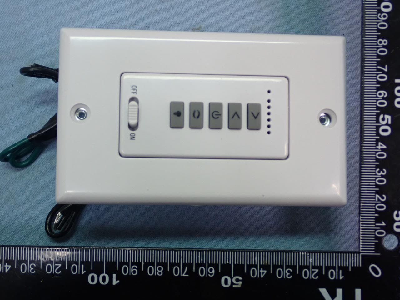
KUJCE11101
May 03, 2022Ceiling Fan Remote Controller(Transmitter)
Equipment Class
DXX - Part 15 Low Power Communication Device Transmitter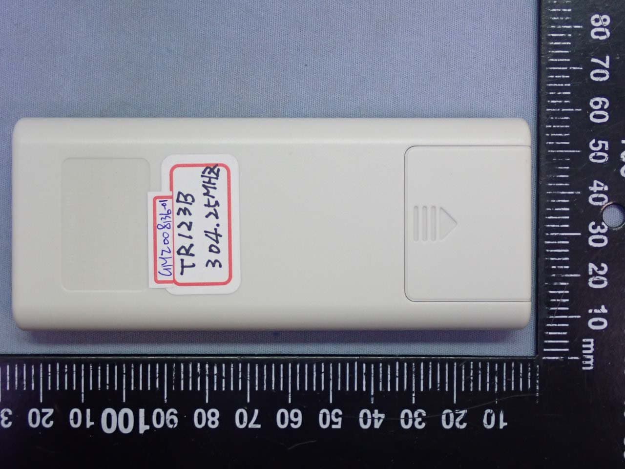
KUJCE10901
Sep 03, 2020Ceiling Fan Remote Controller (Transmitter)
Equipment Class
DSC - Part 15 Security/Remote Control Transmitter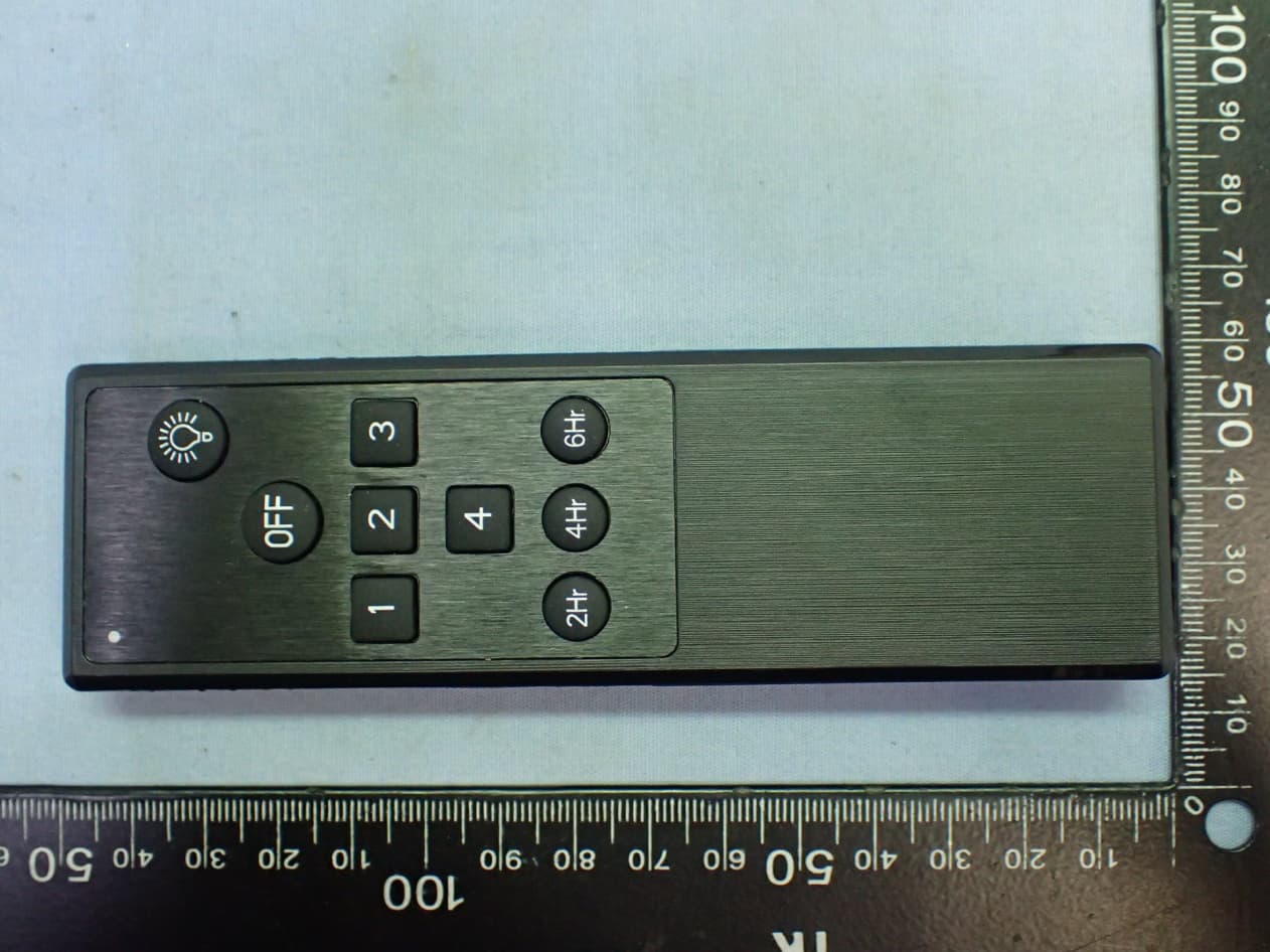
KUJCE10705
Apr 11, 2020Ceiling Fan Remote Controller (Transmitter)
Equipment Class
DSC - Part 15 Security/Remote Control Transmitter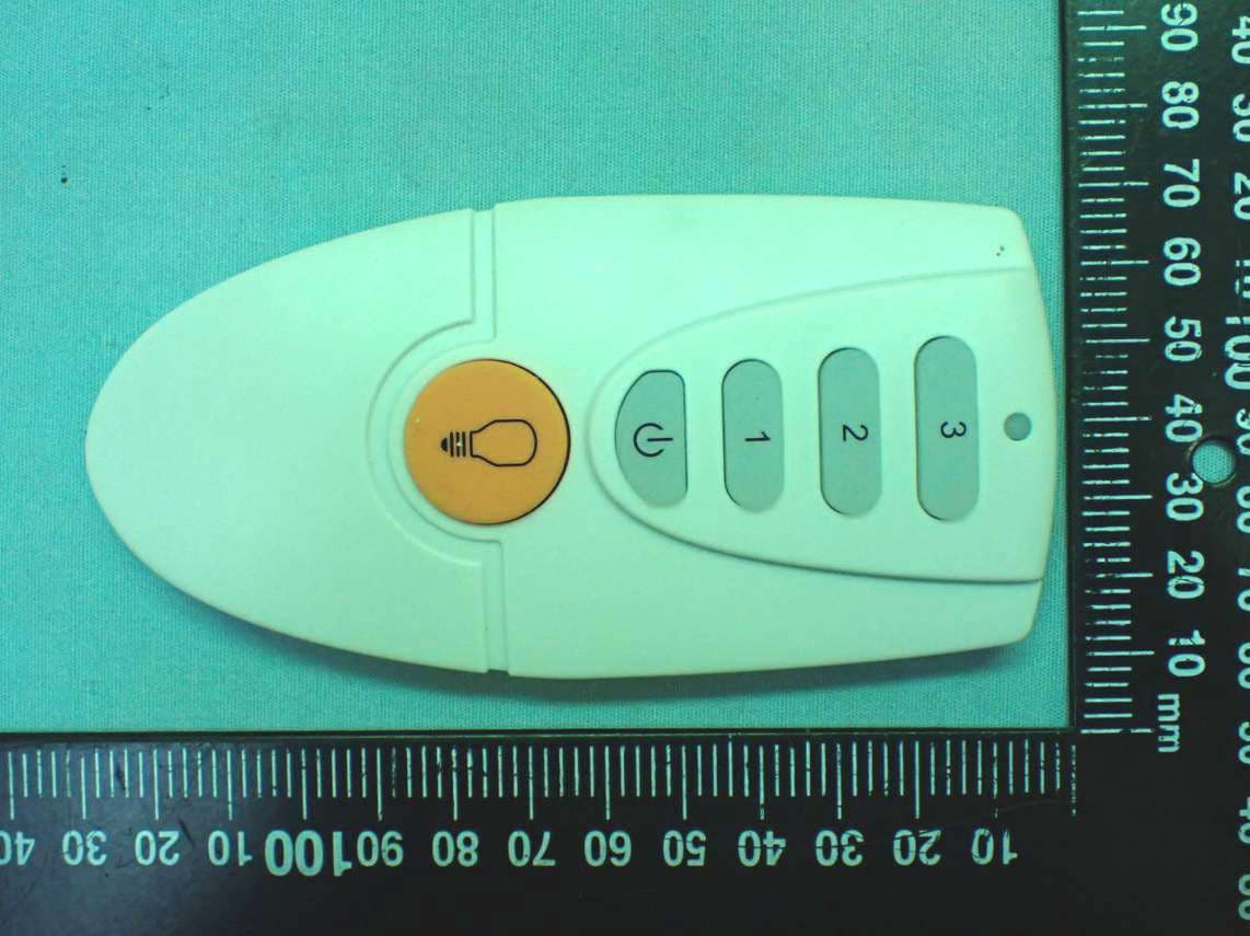
KUJCE10721
Feb 18, 2020Ceiling Fan Remote Controller (Transmitter)
Equipment Class
DSC - Part 15 Security/Remote Control Transmitter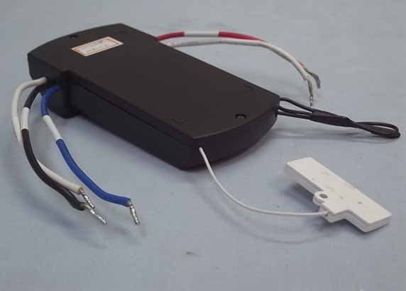
KUJCE10406
Nov 18, 2015CEILING FAN REMOTE CONTROLLER (TRANSMITTER)
Equipment Class
DTS - Digital Transmission System