KUJCE10008Ceiling Fan Remote Controller(Transmitter)
Chungear Industrial Co Ltd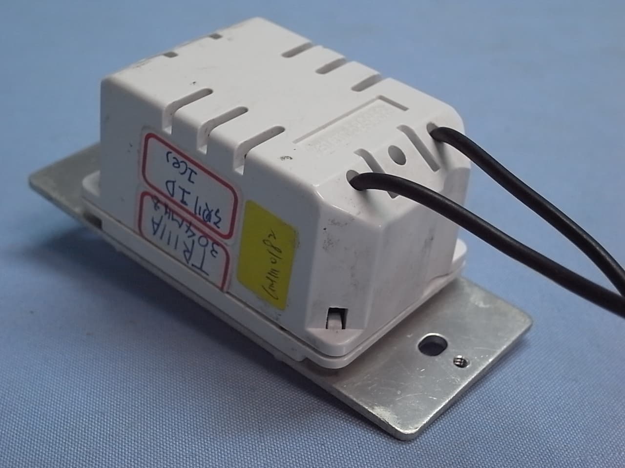
Click to zoom
Application Details
- Equipment Class
- DSC - Part 15 Security/Remote Control Transmitter
- Date of Grant
- Jan 16, 2012
- Application Purpose
- Original Equipment
- Date of Application
- Jan 16, 2012
- Equipment Note
- Ceiling Fan Remote Controller(Transmitter)
- Frequency Range
- 304.00000000 - 304.00000000
- Company
- Chungear Industrial Co Ltd
- Country
- Taiwan
Documents & Files
Document Text
Text extracted from the exhibit documents filed with the FCC. Open a document above to read the original.
Users Manual
Universal Touch Control INSTALLATION & OPERATING INSTRUCTIONS WARNING! SHUT POWER OFF AT FUSE OR CIRCUIT BREAKER Note: The Touch Control System is equipped with a learning frequency function which has 256 code combinations to prevent potential interference from other remote units. The frequency on your Receiver and Transmitter units have been preset at the factory. We recommend changing the frequency while installing your ceiling fan instead of using the initial frequency set by factory (Fig. 1). Please use a small size tool to change the setting. Safety Precautions: WARNING: Disconnect source of electrical power by removing the fuse or switching off the circuit breakers. • Do not use with solid state fans. • Electrical wiring must meet all local and national electrical code requirements. • Electrical source and fan must be 115/120 volts, 60 hz. Maximum fan motor amps 1.0, Maximum light watts 190-incandescent only. 1. RECEIVER INSTALLATION NOTE: Before the electrical power is disabled for the installation of the receiver and wall control; the light kit must be left on the ON position and the ceiling fan on the highest speed. Step 1. Insert Receiver into Hanger Bracket with the flat side of the Receiver facing the ceiling. (Fig. 2) Step 2. Motor to Receiver Electrical Connections: Connect the WHITE wire from the fan to the WHITE wire marked “TO MOTOR N” from the Receiver. Connect the BLACK wire from the fan to the BLACK wire marked “TO MOTOR L” from the Receiver. Connect the BLUE wire from the fan to the BLUE wire marked “For Light” from the Receiver. (Fig. 3) Step 3. Receiver to House Supply Wires Electrical Connections: Connect the WHITE wire (Neutral) from the outlet box to the WHITE wire marked “AC in N” from the receiver. Connect the BLACK wire (Hot) from the outlet box to the BLACK wire marked “AC in L” from the receiver. Secure all wire connections with the plastic wire nuts provided. (Fig. 3) After all splices are made, check to make sure there are no loose strands. As an additional precaution we suggest to secure the plastic wire connectors to the wires with electrical tape. 2. WALL TRANSMITTER INSTALLATION WARNING! HOOK UP “IN SERIES” ONLY. DO NOT CONNECT NEUTRAL SUPPLY WIRE OF ELECTRIC CIRCUIT TO THE TRANSMITTER WALL SWITCH, DAMAGE TO THE TRANSMITTER WALL SWITCH AND POSSIBLE FIRE COULD OCCUR. Step 1. Remove the existing wall plate and switch from the wall outlet box. Step 2. Make the electrical connections as shown in Fig.4. If your outlet box has a ground wire (Green or Bare Copper) connect the Wall Transmitter’s ground wire to it. Otherwise connect the Wall Transmitter’s wire directly to one of the screws from the outlet box . Secure all wire connections with the plastic wire nuts provided. Step 3. Carefully tuck the wire connections inside the outlet box. Use the screws provided to secure the wall transmitter and wall plate to the outlet box. (Fig. 5) CHANGING THE FREQUENCY Step: 1. Within 60 seconds of turning the Receivers AC power ON. Press the transmitter’s “Stop” button. Step: 2. Hold the “Stop” button for over 3 seconds, once the receiver has detected the frequency, the down light will flash twice. This will indicate the receiver has learned the frequency that was previously selected on the transmitter. Note: After the AC power is on, do not press any other button on the transmitter before pressing the “Stop” button doing so will cause the procedure to fail. After completing the steps above, you should be able to operate the ceiling fan and light. Do not connect to hot and common wire of electric circuit or switch will be damaged. Refer to diagram below WARNING! HOOK UP “IN SERIES” ONLY! CAUTION: Do not use fan speed control in canopies where the Mounting is not as described in Fig2 of the installation instructions. If the fan is not responding to the transmitter, please turn the off power of to the receiver and repeat Step 1 and 2 3. OPERATING THE WALL TRANSMITTER The Touch Control™ System includes two sets of face and decorative plate color options. The wall control comes with standard white faceplate attached. If you desire to replace it with the Ivory color faceplate, use a small flat screw driver and gently pry it apart from the top or bottom of the plate. 1. Light Button: Press and release the button to turn the light ON or OFF. Press and hold the button to set the desired light brightness. The light will cycle between bright and dim settings as long as the button is pressed. The light key has an automatic auto-resume feature that allows the light to remain at the same brightness as the last time it was turned off. 2. Speed Buttons Press and release the button for the desired speed. 3. Stop Button This button stops the fan 4. On-OFF This button turns the power off for the fan and light. The installation of your new Touch Control System is complete. Your ceiling fan and light kit assembly must meet the following requirements: 1.Do Not install this fan with wall solid state speed control or wall light dimmer control. It will permanently damage the receiver of remote control and cause the fan function failure. CAUTION: Ceiling Angle shall Not Exceed 30 Degrees, For Mounting controller. Models MR36T NOTICE! FEDERAL COMMUNICATIONS COMMISSION INTERFERENCE STATEMENT This equipment has been tested and found to comply with the limits for a Class B digital device, pursuant to Part 15 of the FCC Rules. These limits are designed to provide reasonable protection against harmful interference in a residential installation. This equipment generates, uses and can radiate radio frequency energy and, if not installed and used in accordance with the instructions, may cause harmful interference to radio communications. However, there is no guarantee that interference will not occur in a particular installation. If this equipment does cause harmful interference to radio or television reception, which can be determined by turning the equipment off and on, the user is encouraged to try …
Text truncated - open the document above for the full version.
Cover Letter(s)
SCS-F18: Project and Product Certification Representative Authorization Letter Page 1 of 2 Rev 2.0 2206 Ringwood Avenue San Jose, CA 95131 Tel: 408-526-1188 Fax: 408-526-1088 Email: [email protected] Project and Product Certification Representative Authorization Letter Revision History Reason for Amendment (current / obsolete) From To Approved Date Initial Release (current) 1.0 1.0 Nov-14-2006 Revised wording (current) 1.0 2.0 Sept–25-2007 SCS-F18: Project and Product Certification Representative Authorization Letter Page 2 of 2 Rev 2.0 Jan. 16, 2012 To: SIEMIC, INC. 2206 Ringwood Avenue, San Jose, CA 95131 USA Dear Sir/Madam, Re: Project and Product Certification Representative Authorization Letter We, Chungear Industrial Co., Ltd. hereby authorize SIEMIC, INC. to act as a Certification Body for certifying for the following project(s): Product Name: Ceiling Fan Remote Controller (Transmitter) Model Name: TR111A We affirm that between SIEMIC and Chungear Industrial Co., Ltd., any difference in understanding, including test plan, measurement methods, applicable standards and relevant procedures and processes have been resolved prior to commencement of testing activities. Sincerely, Peter Chen / Manager Chungear Industrial Co., Ltd. 106 Kanho Rd., Taichung, Taiwan
Cover Letter(s)
SCS-F19: Confidentiality Request Letter Page 1 of 2 Rev 2.0 2206 Ringwood Avenue San Jose, CA 95131 Tel: 408-526-1188 Fax: 408-526-1088 Email: [email protected] Confidentiality Request Letter Revision History Reason for Amendment (current / obsolete) From To Approved Date Initial Release (current) 1.0 1.0 Nov-14-2006 Adding CFR 2.459 1.0 2.0 August – 11 - 2008 SCS-F19: Confidentiality Request Letter Page 2 of 2 Rev 2.0 Jan. 16, 2012 To: Federal Communications Commission Authorization and Evaluation Division 7435 Oakland Mills Road Columbia, MD Confidentiality Request regarding application for certification of FCC ID: KUJCE10008 We hereby request confidential treatment of information accompanying this application as outlined below: - Block Diagram - Operational Description - Schematic Diagram The above materials contain trade secrets and proprietary information not customarily released to the public. The public disclosure of these materials may be harmful to the applicant and provide unjustified benefits to its competitors. The applicant understands that pursuant to Section 0.457 & 0.459 of the Rules, disclosure of this application and all accompanying documentation will not be made before the date of the Grant for this application. Sincerely, Peter Chen / Manager Chungear Industrial Co., Ltd. 106 Kanho Rd., Taichung, Taiwan
External Photos
Chungear Industrial Co., Ltd. Ceiling Fan Remote Controller (Transmitter) FCC ID : KUJCE10008 EUT External Photos Photo 1 General Appearance (Front & Side View) Photo 2 General Appearance (Back & Side View)
ID Label/Location Info
Chungear Industrial Co., Ltd. Ceiling Fan Remote Controller (Transmitter) FCC ID : KUJCE10008 ID Label Location z Label Placement Location (Back View of EUT) z ID Label Format FCC ID KUJCE10008 This device complies with Part 15 of the FCC Rules. Operation is subject to the following two conditions: (1) This device may not cause harmful interference, and (2) this device must accept any interference received, including interference that may cause undesired operation. ID Label Placement Location
Internal Photos
Chungear Industrial Co., Ltd. Ceiling Fan Remote Controller (Transmitter) FCC ID : KUJCE10008 EUT Internal Photos Photo 3 Internal View (Removed Cover) Photo 4 Internal View Chungear Industrial Co., Ltd. Ceiling Fan Remote Controller (Transmitter) FCC ID : KUJCE10008 Photo 5 Internal View (Power Board, Front View) Photo 6 Internal View (Power Board, Back View) Chungear Industrial Co., Ltd. Ceiling Fan Remote Controller (Transmitter) FCC ID : KUJCE10008 Photo 7 Internal View (Control Board, Front View) Photo 8 Internal View (Control Board, Back View) Chungear Industrial Co., Ltd. Ceiling Fan Remote Controller (Transmitter) FCC ID : KUJCE10008 Photo 9 Internal View (Main Board, Front View) Photo 10 Internal View (Main Board, Back View)
Test Report
FCC ID. KUJCE10008 Page 1 of 24 AUDIX Technology Corporation Report No.: EM-F1010035 TEST REPORT FOR CERTIFICATION On Behalf of Chungear Industrial Co., Ltd Ceiling Fan Remote Controller (Transmitter) Model No.: TR111A FCC ID: KUJCE10008 Prepared for : Chungear Industrial Co., Ltd 106 Kanho Rd., Taichung, Taiwan Prepared By : AUDIX Technology Corporation EMC Department No. 53-11, Dingfu, Linkou Dist., New Taipei City 244, Taiwan, R.O.C. Tel : (02) 2609-9301, 2609-2133 Fax : (02) 2609-9303 File Number C1M1110182 Report Number EM-F1010035 Date of Test Nov. 30, 2011 ~ Jan. 13, 2012 Date of Report Jan. 16, 2012 FCC ID. KUJCE10008 Page 2 of 24 AUDIX Technology Corporation Report No.: EM-F1010035 TABLE OF CONTENTS Description Page TEST REPORT CERTIFICATION........................................................................................................3 1. GENERAL INFORMATION ..........................................................................................................4 1.1. Description of Device (EUT) .................................................................................................................. 4 1.2. Tested Supporting System Details .......................................................................................................... 5 1.3. Description of Test Facility..................................................................................................................... 5 1.4. Measurement Uncertainty ....................................................................................................................... 6 2. CONDUCTED EMISSION MEASUREMET................................................................................7 2.1. Test Equipment ....................................................................................................................................... 7 2.2. Block Diagram of Test Setup .................................................................................................................. 7 2.3. Conducted Emission Limits (§15.207) ................................................................................................... 7 2.4. Operating Condition of EUT................................................................................................................... 8 2.5. Test Procedure......................................................................................................................................... 8 2.6. Conducted Emission Measurement Results ............................................................................................ 8 3. RADIATED EMISSION MEASUREMENT ...............................................................................11 3.1. Test Equipment ..................................................................................................................................... 11 3.2. Test Setup.............................................................................................................................................. 11 3.3. Radiation Emission Limits (§15.209) ................................................................................................... 13 3.4. Operating Condition of EUT................................................................................................................. 13 3.5. Test Procedure....................................................................................................................................... 13 3.6. Radiated Emission Noise Measurement Results ................................................................................... 14 4. FUNDAMENTAL MEASUREMENT ..........................................................................................15 4.1. Test Equipment ..................................................................................................................................... 15 4.2. Test Setup.............................................................................................................................................. 15 4.3. Radiation Emission Limits (15.231) ..................................................................................................... 16 4.4. Operating Condition of EUT................................................................................................................. 16 4.5. Test Procedure....................................................................................................................................... 16 4.6. Fundamental Measurement Results ...................................................................................................... 17 5. EMISSION BANDWIDTH MEASUREMENT ...........................................................................18 5.1. Test Equipment ..................................................................................................................................... 18 5.2. Block Diagram of Test Setup ................................................................................................................ 18 5.3. Specification Limits (§15.231-(c))........................................................................................................ 18 5.4. Emission Bandwidth Measurement Results..........................................................................................18 6. PERIODIC OPERATED MEASUREMENT ..............................................................................20 6.1. Test Equipment ..................................................................................................................................... 20 6.2. Block Diagram of Test Setup ................................................................................................................ 20 6.3. Specification Limits [§15.231-(a)-(1)].................................................................................................. 20 6.4. Periodic Operated Measurement Results ..............................…
Text truncated - open the document above for the full version.
Test Setup Photos
FCC ID. KUJCE10008 Page 23 of 24 AUDIX Technology Corporation Report No.: EM-F1010035 8. PHOTOGRAPHS 8.1. Photos of Conducted Emission Measurement 8.2. Photos of Radiated Measurement at Semi-Anechoic Chamber (30~1000MHz) FCC ID. KUJCE10008 Page 24 of 24 AUDIX Technology Corporation Report No.: EM-F1010035 8.3. Photos of Radiated Measurement at Semi-Anechoic Chamber (Above 1GHz) 8.4. Photo of Section RF Conducted Measurement
Contact Information
Applicant
Peter Chen(Engineer Manager)
Test Firm
Audix Technology CorporationLeon Liu
Technical Specifications
| # | Rule Parts | Frequency Range | Power Output |
|---|---|---|---|
| 1 | 15.231 | 304 MHz - 304 MHz | - |
Other Applications from Chungear Industrial Co Ltd
KUJCE11101
May 03, 2022Ceiling Fan Remote Controller(Transmitter)
Equipment Class
DXX - Part 15 Low Power Communication Device Transmitter
KUJCE10901
Sep 03, 2020Ceiling Fan Remote Controller (Transmitter)
Equipment Class
DSC - Part 15 Security/Remote Control Transmitter
KUJCE10705
Apr 11, 2020Ceiling Fan Remote Controller (Transmitter)
Equipment Class
DSC - Part 15 Security/Remote Control Transmitter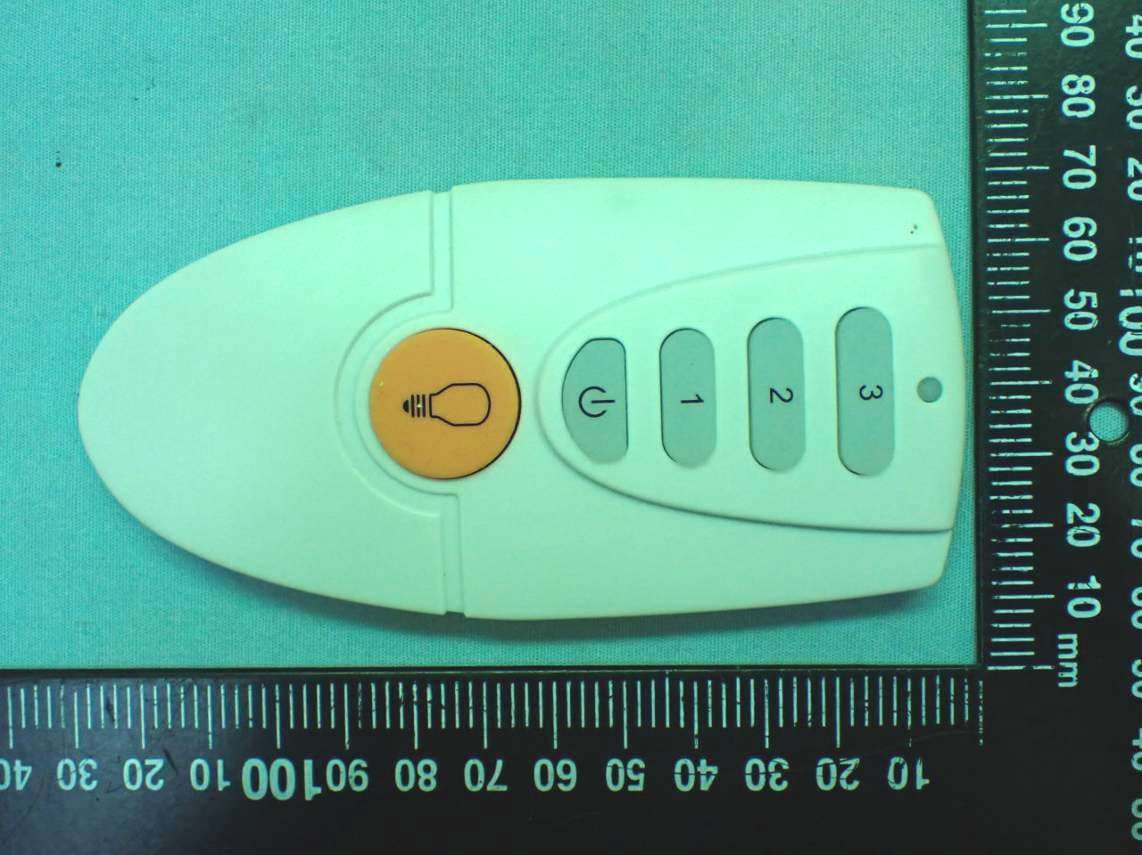
KUJCE10721
Feb 18, 2020Ceiling Fan Remote Controller (Transmitter)
Equipment Class
DSC - Part 15 Security/Remote Control Transmitter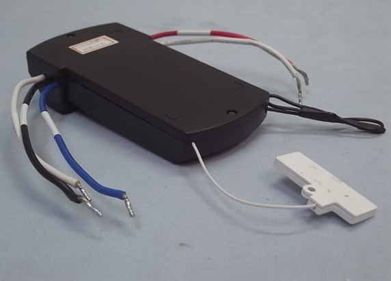
KUJCE10406
Nov 18, 2015CEILING FAN REMOTE CONTROLLER (TRANSMITTER)
Equipment Class
DTS - Digital Transmission System