KUJCE10201Ceiling Fan Remote Controller (Transmitter)
Chungear Industrial Co Ltd
Click to zoom
Application Details
- Equipment Class
- DTS - Digital Transmission System
- Date of Grant
- Sep 11, 2013
- Application Purpose
- Original Equipment
- Date of Application
- Sep 11, 2013
- Equipment Note
- Ceiling Fan Remote Controller (Transmitter)
- Frequency Range
- 2402.00000000 - 2480.00000000
- Company
- Chungear Industrial Co Ltd
- Country
- Taiwan
Documents & Files
Document Text
Text extracted from the exhibit documents filed with the FCC. Open a document above to read the original.
Users Manual
CEILING FAN REMOTE CONTROLLER OPERATION AND INSTALLATION INSTRUCTIONS (Please keep this instruction pamphlet.) IMPORTANT POINTS TO REMEMBER: 1.Read and save these instructions. 2.Please note that all fixed wiring appliances should be installed by a qualified electrician. 3.The supply to the remote control receiver should be connected through a mains switch, i.e. existing wall switch. 4.Disconnect from power supply at wall switch before working on remote control receiver or ceiling fan. 5.Install receiver into the ceiling fan canopy of the fan to ensure proper protection. 6.This unit is to be used for the control of ceiling fan and in a AC110/120V 60Hz power supply only. 7.Do not install in damp locations or immerse in water. (For indoor use only.) 8.Do not pull on or cut leads shorter. 9.Do not drop or bump the unit. 10. PLEASE NOTE: The battery will weaken with age and should be replaced before leaking takes place as this will damage the transmitter. Dispose of used battery properly, keep the battery out of reach of children. 11. CAUTION: To reduce the risk of fire or injury, do not use this product in conjunction with any variable (rheostat) wall control. INSTALLATION INSTRUCTIONS 1.Ceiling fan must be set at HIGH speed and light kit (If any) at ON position by pressing the “Light Switch” after installation. 2.Once the connection has been made, the receiver inserts into the drop rod hanging bracket. The canopy comes up to cover the receiver and bracket. (Mains/Live) BLACK VIEW AFTER INSTALLATION (Fan/Live) BLACK (Light/Live) BLUE WHITE (Fan/Neutral) do not cut) (Leave unconnected and ANTENNA BLACK ANTENNA WHITE (Mains/Neutral) AC POWER SUPPLY IMPORTANT YOU MUST SET CEILING FAN MANUAL SWITCH TO HIGH SPEED AND LIGHT KIT (IF ANY) TO ON POSITION BEFORE OPERATING REMOTE CONTROL. CAUTION: INCORRECT WIRE CONNECTION WOULD DAMAGE THIS RECEIVER. DIP SWITCH 4321 ON DIP CODE SWITCH 1.CODE SWITCH: Codes are set by pushing dip switches up or down. It is imperative that the code used for both transmitter and receiver is exactly the same, otherwise remote controller will not work. Please note the code switch will enable you to operate a second remote controller independently. For example, if you have two ceiling fans with 2 remote control units, set 2 different codes for each set of transmitter/receivers. This means you can operate each ceiling fan independently. 2.Your remote control is ready for use after battery installation. FUNCTIONS OF TRANSMITTER : Turn off the fan. 3 : Turn on the fan at high speed 2 : Turn on the fan at medium speed 1 : Turn on the fan at low speed. LIGHT: ON/OFF - Press and release immediately to turn on or off the light DIMMER- Press and hold to dim or brighten lights to the desired level and release. (Only for the tungsten bulb.) If light load over 190W, light will shut down. MODEL:TR158A ANTENNA AC POWER INPUT BLACK WHITE L N FAN MOTOR TO FAN/LIVE TO LIGHT LIVE TO FAN / LIGHT / NEUTRAL BLACK BLUE WHITE MODEL:MR101F Ceiling Fan Remote Control Wiring Connection TRANSMITTER FEDERAL COMMUNICATIONS COMMISSION INTERFERENCE STATEMENT This equipment has been tested and found to comply with the limits for a Class B digital device, pursuant to Part 15 of the FCC Rules. These limits are designed to provide reasonable protection against harmful interference in a residential installation. This equipment generates, uses and can radiate radio frequency energy and, if not installed and used in accordance with the instructions, may cause harmful interference to radio communications. However, there is no guarantee that interference will not occur in a particular installation. If this equipment does cause harmful interference to radio or television reception, which can be determined by turning the equipment off and on, the user is encouraged to try to correct the interference by one or more of the following measures: -- Reorient or relocate the receiving antenna. -- Increase the separation between the equipment and receiver. -- Connect the equipment into an outlet on a circuit different from that to which the receiver is connected. -- Consult the dealer or an experienced radio/TV technician for help. CAUTION: To assure continued FCC compliance: 1. Any changes or modifications not expressly approved by the grantee of this device could void the user's authority to operate the equipment. 2. This equipment complies with FCC radiation exposure limits set forth for an uncontrolled environment. This equipment should be installed and operated with minimum distance 20cm between the radiator & your body. FCC ID:KUJCE10201 This device complies with Part 15 of the FCC Rules. Operation is subject to the following two conditions: (1) This device may not cause harmful interference, and (2) this device must accept any interference received, including interference that may cause undesired operation.
Cover Letter(s)
SCS-F18: Project and Product Certification Representative Authorization Letter Page 1 of 2 Rev 3.0 775 Montague Expressway Milpitas, CA 95035 Tel: 408-526-1188 Fax: 408-526-1088 Email: [email protected] Project and Product Certification Representative Authorization Letter Reason for Amendment (current / obsolete) Revision History Approved Date From To Initial Release (obsolete) 1.0 1.0 Nov-14-2006 Revised wording (obsolete) 1.0 2.0 Sept–25-2007 Updated company template (current) 2.0 3.0 Jan-31-2012 SCS-F18: Project and Product Certification Representative Authorization Letter Page 2 of 2 Rev 3.0 Jul. 12, 2013 To: SIEMIC, INC. 775 Montague Expressway, Milpitas, CA 95035 USA Dear Sir/Madam, Re: Project and Product Certification Representative Authorization Letter We, Chungear Industrial Co., Ltd. hereby authorize SIEMIC, INC. to act as a Certification Body for certifying for the following project(s): Product Name: Ceiling Fan Remote Controller Model Name: MR101F We affirm that between SIEMIC and Chungear Industrial Co., Ltd. any difference in understanding, including test plan, measurement methods, applicable standards and relevant procedures and processes have been resolved prior to commencement of testing activities. Sincerely, Peter Chen / Manager CHUNGEAR INDUSTRIAL CO., LTD. 106 KANHO RD,TAICHUNG ,TAIWAN
Cover Letter(s)
SCS-F19: Confidentiality Request Letter Page 1 of 2 Rev 3.0 775 Montague Expressway Milpitas, CA 95035 Tel: 408-526-1188 Fax: 408-526-1088 Email: [email protected] Confidentiality Request Letter Reason for Amendment (current / obsolete) Revision History Approved Date From To Initial Release (obsolete) 1.0 1.0 Nov-14-2006 Adding CFR 2.459 (obsolete) 1.0 2.0 August – 11 - 2008 Updated company template & Added text box (current) 2.0 3.0 Jan-31-2012 SCS-F19: Confidentiality Request Letter Page 2 of 2 Rev 3.0 Jul. 12, 2013 To: Federal Communications Commission Authorization and Evaluation Division 7435 Oakland Mills Road Columbia, MD Subject: Permanent Confidentiality Request for FCC ID: KUJCE10201 We hereby request confidential treatment of information accompanying this application as outlined below: - Block Diagram - Schematics - Operational Description The above materials contain trade secrets and proprietary information not customarily released to the public. The public disclosure of these materials may be harmful to the applicant and provide unjustified benefits to its competitors. The applicant understands that pursuant to Section 0.457 & 0.459 of the Rules, disclosure of this application and all accompanying documentation will not be made before the date of the Grant for this application. Sincerely, Peter Chen / Manager CHUNGEAR INDUSTRIAL CO., LTD. 106 KANHO RD,TAICHUNG ,TAIWAN
External Photos
Chungear Industrial Co., Ltd. Ceiling Fan Remote Controller FCC ID : KUJCE10201 EUT External Photos Photo 1 General Appearance (Front & Side View) Photo 2 General Appearance (Back & Side View)
ID Label/Location Info
Chungear Industrial Co., Ltd. Ceiling Fan Remote Controller FCC ID : KUJCE10201 ID Label Location z Label Placement Location (Back View of EUT) z IC Label Format ID Label Placement Location
Internal Photos
Chungear Industrial Co., Ltd. Ceiling Fan Remote Controller FCC ID : KUJCE10201 EUT Internal Photos Photo 3 Internal View (Removed Cover) Photo 4 Internal View (Main Board, Front View) Chungear Industrial Co., Ltd. Ceiling Fan Remote Controller FCC ID : KUJCE10201 Photo 5 Internal View (Main Board, Front View with Removed shielded Cover) Photo 6 Internal View (Main Board, Back View)
RF Exposure Info
Maximum Permissive Exposure FCC ID: KUJCE10201 Product Name: Ceiling Fan Remote Controller Model No: MR101F Chungear Industrial Co., Ltd. declares that the product described above has been evaluated and found to comply with the RF exposure limits for humans, as specified based on ANSI/FCC recommendation. Based on safety distance 20cm, the antenna gain of 2.4GHz is 6.03 dBi, and the power output is 0.177mW, the power density is 0.0001411 mW/cm^2. RF Exposure Calculations: S = (P * G) / (4* π * r^2) or r = (P * G) / (4 * π * S) Where S = Power Density in mW/cm^2 P = -7.52dBm =0.177mW G = 6.03 dBi = 4.008 Numerical r = 20cm S = 0.177*4.008 / 4*π* 20^2 = 0.0001411mW/cm^2 Sincerely Yours, ____________________________________ Mr. Ben Cheng Manager AUDIX Technology Corporation
Test Report
FCC ID. KUJCE10201 Page 1 of 44 AUDIX Technology Corporation Report No. EM-F1020564 APPLICATION FOR CERTIFICATION On Behalf of Chungear Industrial Co., Ltd. Ceiling Fan Remote Controller Model No.MR101F FCC ID : KUJCE10201 Prepared for : Chungear Industrial Co., Ltd. 106 Kanho Rd., Taichung, Taiwan Prepared by : AUDIX Technology Corporation EMC Department No. 53-11, Dingfu, Linkou Dist., New Taipei City 244, Taiwan, R.O.C. Tel : (02) 2609-9301, 2609-2133 Fax: (02) 2609-9303 File Number C1M1307126 Report Number EM-F1020564 Date of Test Aug. 05 ~ 10, 2013 Date of Report Aug. 14, 2013 FCC ID. KUJCE10201 Page 2 of 44 AUDIX Technology Corporation Report No. EM-F1020564 TABLE OF CONTENTS Description Page TEST REPORT CERTIFICATION .......................................................................................................4 1. GENERAL INFORMATION .........................................................................................................5 1.1. Description of Device (EUT) .................................................................................................................. 5 1.2. Tested Supporting System Details .......................................................................................................... 6 1.3. Description of Test Facility .................................................................................................................... 6 1.4. Measurement Uncertainty ....................................................................................................................... 7 2. CONDUCTED EMISSION MEASUREMENT ............................................................................8 2.1. Test Equipment ....................................................................................................................................... 8 2.2. Block Diagram of Test Setup.................................................................................................................. 8 2.3. Powerline Conducted Emission Limit (§15.207, Class B) ..................................................................... 8 2.4. Operating Condition of EUT .................................................................................................................. 9 2.5. Test Procedure ........................................................................................................................................ 9 2.6. Powerline Conducted Emission Measurement Results ........................................................................... 9 3. RADIATED EMISSION MEASUREMENT ..............................................................................12 3.1. Test Equipment ..................................................................................................................................... 12 3.2. Test Setup ............................................................................................................................................. 12 3.3. Radiated Emission Limits (§15.209) .................................................................................................... 14 3.4. Operating Condition of EUT ................................................................................................................ 14 3.5. Test Procedure ...................................................................................................................................... 15 3.6. Test Results ........................................................................................................................................... 16 4. 6dB BANDWIDTH MEASUREMENT .......................................................................................28 4.1. Test Equipment ..................................................................................................................................... 28 4.2. Block Diagram of Test Setup................................................................................................................ 28 4.3. Specification Limits [§15.247(a)(2)] .................................................................................................... 28 4.4. Operating Condition of EUT ................................................................................................................ 28 4.5. Test Procedure ...................................................................................................................................... 28 4.6. Test Results ........................................................................................................................................... 29 5. MAXIMUM PEAK OUTPUT POWER MEASUREMENT .....................................................32 5.1. Test Equipment ..................................................................................................................................... 32 5.2. Block Diagram of Test Setup................................................................................................................ 32 5.3. Specification Limits [§15.247(b)-(3)] ................................................................................................... 32 5.4. Operating Condition of EUT ................................................................................................................ 32 5.5. Test Procedure ...................................................................................................................................... 32 5.6. Test Results ........................................................................................................................................... 33 6. EMISSION LIMITATIONS MEASUREMENT ........................................................................34 7. BAND EDGES MEASUREMENT ...............................................................................................35 7.1. Test Equipment ..........................................................................................…
Text truncated - open the document above for the full version.
Test Setup Photos
FCC ID. KUJCE10201 Page 42 of 44 AUDIX Technology Corporation Report No. EM-F1020564 10. PHOTOGRAPHS 10.1.Photos of Conducted Emission Measurement FRONT VIEW OF CONDUCTED MEASUREMENT BACK VIEW OF CONDUCTED MEASUREMENT FCC ID. KUJCE10201 Page 43 of 44 AUDIX Technology Corporation Report No. EM-F1020564 10.2.Photos of Radiated Measurement at Semi-Anechoic Chamber 10.2.1.Frequency Below 1GHz 10.2.2. Frequency Above 1GHz FCC ID. KUJCE10201 Page 44 of 44 AUDIX Technology Corporation Report No. EM-F1020564 10.3.Photo of Section RF Conducted Measurement
Contact Information
Applicant
Peter Chen(Engineer Manager)
Test Firm
Audix Technology CorporationLeon Liu
Technical Specifications
| # | Rule Parts | Frequency Range | Power Output |
|---|---|---|---|
| 1 | 15C | 2.40 GHz - 2.48 GHz | 177.00 µW |
Other Applications from Chungear Industrial Co Ltd
KUJCE11101
May 03, 2022Ceiling Fan Remote Controller(Transmitter)
Equipment Class
DXX - Part 15 Low Power Communication Device Transmitter
KUJCE10901
Sep 03, 2020Ceiling Fan Remote Controller (Transmitter)
Equipment Class
DSC - Part 15 Security/Remote Control Transmitter
KUJCE10705
Apr 11, 2020Ceiling Fan Remote Controller (Transmitter)
Equipment Class
DSC - Part 15 Security/Remote Control Transmitter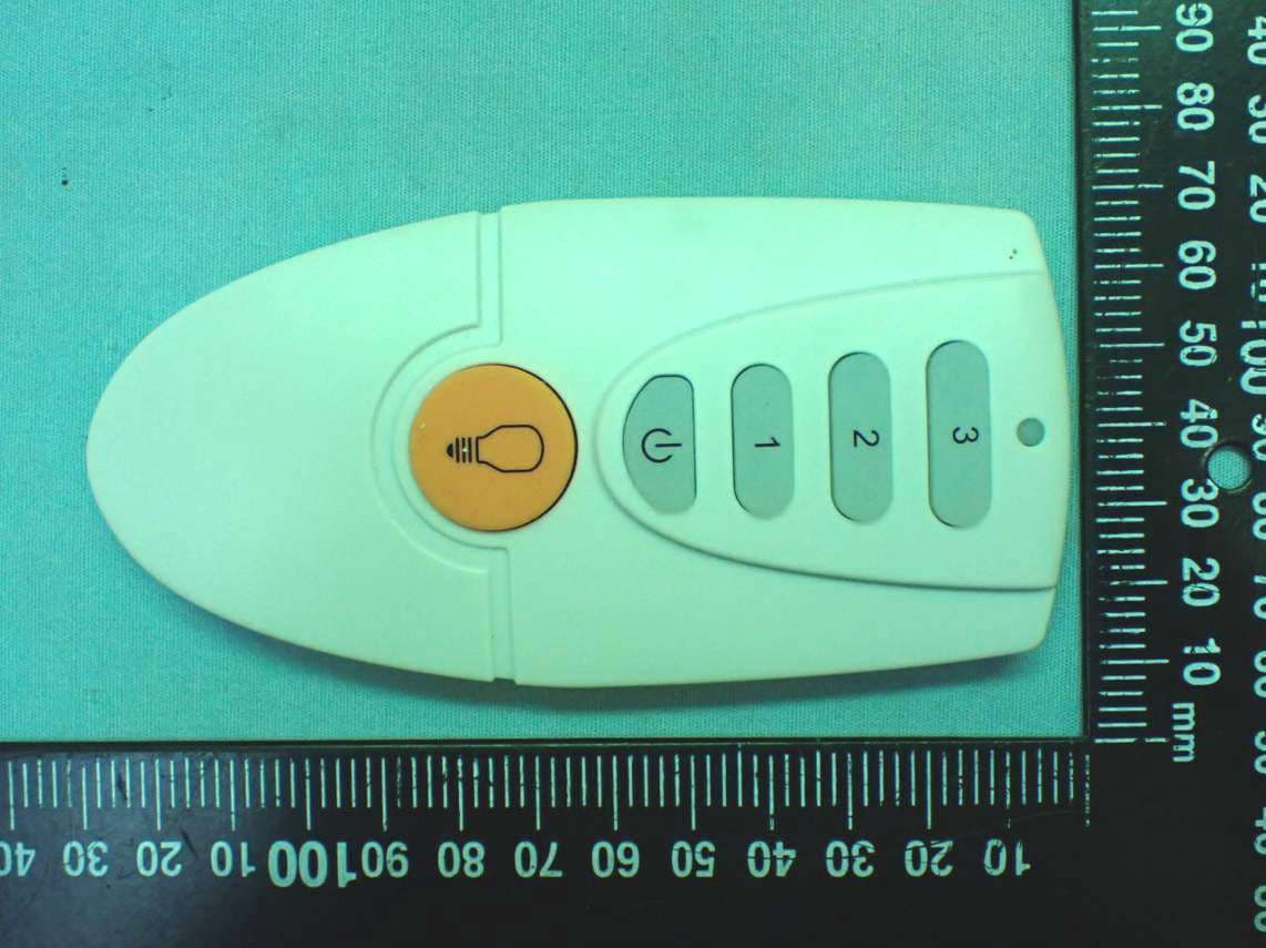
KUJCE10721
Feb 18, 2020Ceiling Fan Remote Controller (Transmitter)
Equipment Class
DSC - Part 15 Security/Remote Control Transmitter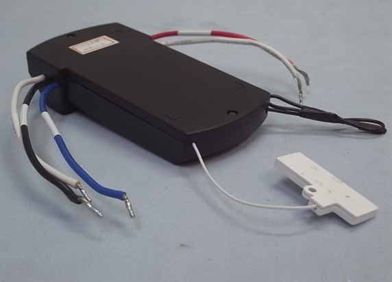
KUJCE10406
Nov 18, 2015CEILING FAN REMOTE CONTROLLER (TRANSMITTER)
Equipment Class
DTS - Digital Transmission System