KUJCE10410CEILING FAN REMOTE CONTROLLER (TRANSMITTER)
Chungear Industrial Co Ltd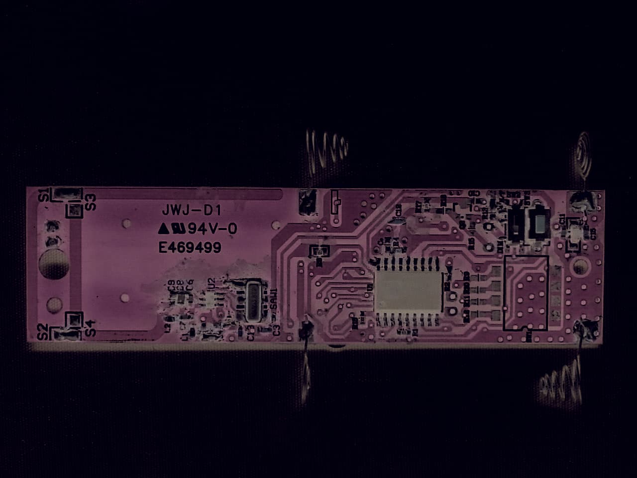
Click to zoom
Application Details
- Equipment Class
- DSC - Part 15 Security/Remote Control Transmitter
- Date of Grant
- Nov 09, 2015
- Application Purpose
- Original Equipment
- Date of Application
- Nov 09, 2015
- Equipment Note
- CEILING FAN REMOTE CONTROLLER (TRANSMITTER)
- Frequency Range
- 303.88000000 - 303.88000000
- Company
- Chungear Industrial Co Ltd
- Country
- Taiwan
Documents & Files
Document Text
Text extracted from the exhibit documents filed with the FCC. Open a document above to read the original.
Users Manual
2H4H8H H a r b o r B r e e z e H a r b o r B r e e z e Black (hot/power) Push-on Connector White (neutral) Red White White White Black Blue Blue Blac k Antenna Receiver 2H4H8H ASSEMBLY INSTRUCTIONS OPERATING INSTRUCTIONS SAFETY INFORMATION 1. Use pull chains to set fan speed to high and light on. 2. Turn off circuit breakers and wall switch to the fan. DANGER: Failure to disconnect power supply prior to installation may result in serious injury or death. 3. Lower the canopy of the previously assembled fan and insert receiver. Note: If installing the remote in a new fan, insert the receiver in the mounting bracket before wiring the fan. Wire the fan according to these instructions. Then, continue fan assembly as directed in the fan’s instruction manual. • Connect the Red wire with red label from the receiver to the Black (hot/power) supply wire. • Connect the White wire with red label from the receiver to the White (neutral) supply wire. REMOTE WITH TIMER ITEM #0745359 MODEL #41235 Serial Number Purchase Date ATTACH YOUR RECEIPT HERE Harbor Breeze ® is a registered trademark of LF, LLC. All rights reserved. XXXXXXX 9130 • 101315 Read instructions completely before installing wall control. CAUTION: Do not install in damp locations. For indoor use only. CAUTION: Do not use with fans that have integrated remote controls. CAUTION: Be sure the outlet box is properly grounded or that a green or bare (ground) wire is present. CAUTION: This unit is intended to control a ceiling fan with electrical source of AC 110/120V, 60Hz. CAUTION: This device complies with Part 15 of the FCC Rules. Operation is subject to the following two conditions: (1) this device may not cause interference, and (2) this device must accept any interference received, including interference that may cause undesired operation. WARNING: If the color of the household supply wires is different than what is referred to in the instructions below, a professional electrician should determine proper wiring. Printed in China 3 4 1 2 5 6 7 8 1 4. Secure all wiring connections with wire connectors according to diagram and these steps: • Connect the Blue wire with white label from the receiver to the Blue fan wire. • Connect the Black wire with white label from the receiver to the Black fan wire. • Connect the White wire with white label from the receiver to the White fan wire. Fan Pull Chain Light Pull Chain Wall Bracket Mounting Screws Light Control Home Shield Delay Off Timers Low Medium High Learn D/O Canopy Receiver High LED Indicator Battery 5. Wrap electrical tape (not included) around each push-on connector down to the wire. Then, push wire connections into the outlet box. Place the Green and White wire connections on the opposite side of the outlet box from the Black and Blue wire connections. 6. Turn on power supply and wall switch to the fan. 7. Remove the battery cover from the back of the remote and install two AAA batteries. Replace the battery cover and press the high button to ensure the LED indicator illuminates and the fan turns on. 8. If desired, the wall bracket can be attached to a wall using the mounting screws from the hardware bag. Slide small plate over mounting screws, then rest the remote in the wall bracket for easy storage. 1. To operate the fan using the remote, press and release the following buttons: High - Turns fan on high speed. Medium - Turns fan on medium speed. Low - Turns fan on low speed. Fan Off - Turns fan off. Walk Away Light Delay TM - Tap once will turn fan light off after 1 minute. Note: Light blinks to confirm that Walk Away Light Delay is active. Press any other button to cancel. Timer - With fan on, press desired timer button (2, 4 or 8 hour). Fan light (if applicable) blinks to confirm timer is active. Press fan off to cancel timer. Home Shield TM - Press and hold Light and Delay buttons for 3 seconds. Lights cycle on for 5-20 minutes and off for 60 minutes, simulating occupancy. Cycle repeats continuously until any other button is pushed to discontinue Home Shield mode. Light Control - Light Control: Incandescent Bulbs - Press light control to turn lights off and on. Press and hold light control to dim or brighten the lights. CFL -Turns the lights on and off. Note: The dimmer function does not work with CFL bulbs. D/O - Switch should be set to “O” to for CFLs, which disables the dimming function. Flip to “D” for incandescent and other dimmable bulbs. Learn - Syncs remote control to receiver. The remote was synced at the factory. Should it become necessary to re-sync the remote. Turn off the main power, then turn it back on. Within 30 seconds, use a small screwdriver to press and hold the learn button on the remote for 3 seconds. The fan will turn on and light (if applicable) will blink three times, signaling a successful synchronization. Questions? Call our customer service department at 1-800-643-0067, 8 a.m. - 5 p.m., EST, Friday. Remote Qty. 1 Wall Bracket Qty. 1 Battery Qty. 2 Receiver Qty. 1 Wire Connector Qty. 3 Mounting Screw Qty. 2 CAUTION: To assure continued FCC compliance: FCC ID:KUJCE10410 This device complies with Part 15 of the FCC Rules. Operation is subject to the following two conditions: (1) This device may not cause harmful interference, and (2) this device must accept any interference received, including interference that may cause undesired operation. Any changes or modifications not expressly approved by the grantee of this device could void the user's authority to operate the equipment.
ID Label/Location Info
Chungear Industrial Co., Ltd. Ceiling Fan Remote Controller (Transmitter) FCC ID : KUJCE10410 ID Label Location z Label Placement Location (Back View of EUT) z ID Label Format FCC ID:KUJCE10410 This device complies with Part 15 of the FCC Rules. Operation is subject to the following two conditions: (1) This device may not cause harmful interference, and (2) this device must accept any interference received, including interference that may cause undesired operation. ID Label Placement Location
Internal Photos
Chungear Industrial Co., Ltd. Ceiling Fan Remote Controller (Transmitter) FCC ID : KUJCE10410 EUT Internal Photos Photo 3 Internal View (Removed Battery Cover) Photo 4 Internal View (Removed Cover) Chungear Industrial Co., Ltd. Ceiling Fan Remote Controller (Transmitter) FCC ID : KUJCE10410 Photo 5 Internal View (Main Board, Front View) Photo 6 Internal View (Main Board, Back View)
Test Report
Page 1 of 25 AUDIX Technology Corp. Tel: +886 2 26099301 No. 53-11, Dingfu, Linkou, Dist., Fax: +886 2 26099303 New Taipei City244, Taiwan File Number: C1M1510176 Report Number: EM-F150653 This test report may be reproduced in full only. The document may only be updated by AUDIX Technology Corp. personnel Any changes will be noted in the Document History section of the report. FCC 15.231 Report for Chungear Industrial Co., Ltd 106 Kanho Rd., Taichung, Taiwan Product Name : Ceiling Fan Remote Controller (Transmitter) Model Name : TR121B FCC ID : KUJCE10410 Page 2 of 25 AUDIX Technology Corp. Tel: +886 2 26099301 No. 53-11, Dingfu, Linkou, Dist., Fax: +886 2 26099303 New Taipei City244, Taiwan File Number: C1M1510176 Report Number: EM-F150653 This test report may be reproduced in full only. The document may only be updated by AUDIX Technology Corp. personnel Any changes will be noted in the Document History section of the report. TABLE OF CONTENTS Description Page TEST REPORT CERTIFICATION ............................................................................................ 3 1. REPORT HISTORY............................................................................................................. 4 2. SUMMARY OF TEST RESULTS ...................................................................................... 5 3. GENERAL INFORMATION .............................................................................................. 6 3.1. Description of EUT .................................................................................................................... 6 3.2. EUT Specifications Assessed in Current Report ..................................................................... 6 3.3. Antenna Information ................................................................................................................. 6 3.4. Tested Supporting System List ................................................................................................. 7 3.5. Setup Configuration .................................................................................................................. 8 3.6. Operating Condition of EUT .................................................................................................... 8 3.7. Description of Test Facility ....................................................................................................... 8 3.8. Measurement Uncertainty ........................................................................................................ 9 4. MEASUREMENT EQUIPMENT LIST ........................................................................... 10 4.1. Radiated Emission Measurement ........................................................................................... 10 4.2. RF Conducted Measurement .................................................................................................. 10 5. CONDUCTED EMISSION MEASUREMET .................................................................. 11 6. RADIATED EMISSION MEASUREMENT ................................................................... 12 6.1. Block Diagram of Test Setup .................................................................................................. 12 6.2. Radiated Emission Limits ....................................................................................................... 13 6.3. Test Procedure ......................................................................................................................... 15 6.4. Measurement Result Explanation .......................................................................................... 16 6.5. Test Results ............................................................................................................................... 16 7. EMISSION BANDWIDTH MEASUREMENT ............................................................... 21 7.1. Block Diagram of Test Setup .................................................................................................. 21 7.2. Specification Limits ................................................................................................................. 21 7.3. Test Procedure ......................................................................................................................... 21 7.4. Test Results ............................................................................................................................... 22 8. PERIODIC OPERATED MEASUREMENT .................................................................. 23 8.1. Block Diagram of Test Setup .................................................................................................. 23 8.2. Specification Limits ................................................................................................................. 23 8.3. Test Procedure ......................................................................................................................... 23 8.4. Test Results ............................................................................................................................... 24 9. DEVIATION TO TEST SPECIFICATIONS................................................................... 25 APPENDIX A TEST PHOTOGRAPHS Page 3 of 25 AUDIX Technology Corp. Tel: +886 2 26099301 No. 53-11, Dingfu, Linkou, Dist., Fax: +886 2 26099303 New Taipei City244, Taiwan File Number: C1M1510176 Report Number: EM-F150653 This test report may be reproduced in full only. The document may only be updated by AUDIX Technology Corp. personnel Any changes will be noted in the Document History section of the report. TEST REPORT CERTIFICATION Applicant : Chungear Industrial Co., Ltd Manufacture : Chungear Industrial Co., Ltd Product Name : Ceiling Fan Remote Controller (Transmitter) Model No. : TR121B Serial No. : N/A Brand : Futaba Applicable Standards: FCC Rules and Regulations Part 15 Subpart C, Oct. 2014 ANSI C63.…
Text truncated - open the document above for the full version.
Test Setup Photos
APPENDIX A AUDIX Technology Corp. Tel: +886 2 26099301 No. 53-11, Dingfu, Linkou, Dist., Fax: +886 2 26099303 New Taipei City244, Taiwan File Number: C1M1510176 This test report may be reproduced in full only. The document may only be updated by AUDIX Technology Corp. personnel Any changes will be noted in the Document History section of the report. APPDNDIX A TEST PHOTOGRAPHS (Model: TR121B) APPENDIX A-Page 1 of 4 AUDIX Technology Corp. Tel: +886 2 26099301 No. 53-11, Dingfu, Linkou, Dist., Fax: +886 2 26099303 New Taipei City244, Taiwan File Number: C1M1510176 This test report may be reproduced in full only. The document may only be updated by AUDIX Technology Corp. personnel Any changes will be noted in the Document History section of the report. A.1 Radiated Measurement at Semi-Anechoic Chamber Frequency Below 1GHz EUT on Stand EUT on Side APPENDIX A-Page 2 of 4 AUDIX Technology Corp. Tel: +886 2 26099301 No. 53-11, Dingfu, Linkou, Dist., Fax: +886 2 26099303 New Taipei City244, Taiwan File Number: C1M1510176 This test report may be reproduced in full only. The document may only be updated by AUDIX Technology Corp. personnel Any changes will be noted in the Document History section of the report. EUT on Lie Frequency Above 1GHz EUT on Stand APPENDIX A-Page 3 of 4 AUDIX Technology Corp. Tel: +886 2 26099301 No. 53-11, Dingfu, Linkou, Dist., Fax: +886 2 26099303 New Taipei City244, Taiwan File Number: C1M1510176 This test report may be reproduced in full only. The document may only be updated by AUDIX Technology Corp. personnel Any changes will be noted in the Document History section of the report. EUT on Side EUT on Lie APPENDIX A-Page 4 of 4 AUDIX Technology Corp. Tel: +886 2 26099301 No. 53-11, Dingfu, Linkou, Dist., Fax: +886 2 26099303 New Taipei City244, Taiwan File Number: C1M1510176 This test report may be reproduced in full only. The document may only be updated by AUDIX Technology Corp. personnel Any changes will be noted in the Document History section of the report. A.2 RF Near Field Measurement
Contact Information
Applicant
Peter Chen(Engineer Manager)
Technical Contact
AUDIX Technology CorporationJarwei Wang
[email protected](886)2-2609-9301
No. 53-11, Dingfu, Linkou Dist., · New Taipei City · Taiwan
Test Firm
Audix Technology CorporationLeon Liu
Technical Specifications
| # | Rule Parts | Frequency Range | Power Output |
|---|---|---|---|
| 1 | 15.231 | 303.88 MHz - 303.88 MHz | - |
Other Applications from Chungear Industrial Co Ltd
KUJCE11101
May 03, 2022Ceiling Fan Remote Controller(Transmitter)
Equipment Class
DXX - Part 15 Low Power Communication Device Transmitter
KUJCE10901
Sep 03, 2020Ceiling Fan Remote Controller (Transmitter)
Equipment Class
DSC - Part 15 Security/Remote Control Transmitter
KUJCE10705
Apr 11, 2020Ceiling Fan Remote Controller (Transmitter)
Equipment Class
DSC - Part 15 Security/Remote Control Transmitter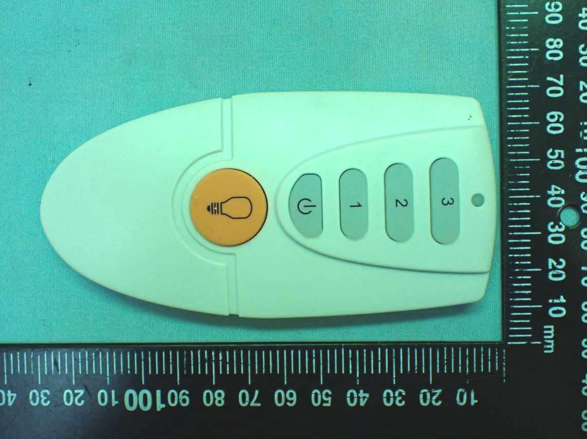
KUJCE10721
Feb 18, 2020Ceiling Fan Remote Controller (Transmitter)
Equipment Class
DSC - Part 15 Security/Remote Control Transmitter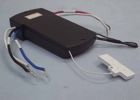
KUJCE10406
Nov 18, 2015CEILING FAN REMOTE CONTROLLER (TRANSMITTER)
Equipment Class
DTS - Digital Transmission System