KXYD8XXXXXDigital Frame (Wi-Fi)
China Great-Wall Computer Shenzhen Co. Ltd.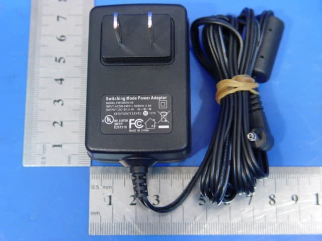
Click to zoom
Application Details
- Equipment Class
- DTS - Digital Transmission System
- Date of Grant
- Sep 11, 2007
- Application Purpose
- Original Equipment
- Date of Application
- Sep 11, 2007
- Equipment Note
- Digital Frame (Wi-Fi)
- Frequency Range
- 2412.00000000 - 2462.00000000
- Country
- China
Documents & Files
Document Text
Text extracted from the exhibit documents filed with the FCC. Open a document above to read the original.
Users Manual
eStarling Photo Frame setup and user guide Thank you for choosing the eStarling Digital Photo Frame. Please follow this guide to setup and use your new eStarling frame. *** Before setting up your eStarling frame *** Please prepare the following items before you go begin the following set up of your eStarling frame. - your eStarling frame, along with the power supply and USB cable - a powered on PC with Internet connection - Internet connected WiFi network with known SSID (network name), authentication type and the corresponding encryption key ( WEP ) or Pre-Shared Key, PSK ( WPA ), if using encryption Setting up your eStarling Digital Photo Frame Use your PC to visit “ www.seeframe.com ” and click “Setup Now!” and follow the installation steps below: Step1: Power up your eStarling™ frame by plugging in the power cord. A message will appear on the frame “Wi-Fi Connecting” Indicating that the frame is searching for an available WiFi signal. (Please Note: Some models of eStarling frame include an EXTERNAL USB WiFi Adaptoe. If your frame includes the external adaptor, please insert the adaptor into the USB port on the frame before powering up the frame. Step2: Use the included USB cable to connect your eStarling™ frame to your Mac or PC (then click “Next”) Step3: You will reach the page “ www.seeframe.com/inside2.html “ for downloading the WiFi connection setup utility – NETCONFIG Choose the correct Operating System (Windows or Mac) and click “Download Now!” to start downloading NETCONFIG. Leave this webpage open after download of NETCONFIG has been completed. Run NETCONFIG and follow the steps below to setup the connection of your eStarling frame to the WiFi network. Setting up the WiFi connection between your WiFi router/AP and eStarling frame I. After you powered up your eStarling frame at Step1: above, you will see the eStarling logo and the frame will start to search for the WiFi network. II. For the first time setup of your eStarling frame, the following message may show up (this step may takes as long as 2min.) III. Run the NETCONFIG utility downloaded from Step3 above. Choose “Scan for available WiFi network and setup manually” if you are running the NETCONFIG utility from a desktop or laptop PC which have WiFi enabled. (Re. : it is NOT recommended to use the “Full manual setup” mode unless you know all the details about your WiFi network) IV. The PC will scan for available WiFi network. Highlight your WiFi network and click “Next”. ************************************************************************************** NETCONFIG will jump to the last step directly if : 1) your PC had been connected/is connecting to the WEP encrypted network, NETCONFIG will automatically extract the encryption key from your PC 2) the selected network is of OPEN type, no encryption is implemented Click “Configure Frame” to send the configuration data to your eStarling frame and go to step VI. To continue the setup process ************************************************************************************ V. NETCONFIG will detect the authentication mode (WEP or WPA) of your selected WiFi network and jump to the corresponding setup page accordingly. - For WEP encrypted network, enter the WEP encryption key and choose the encryption mode (choose none for open network). - For WPA encrypted network, enter the WPA Pre-Shared Key (PSK) and the encryption key type (if you are not sure, try TKIP first as this is the most common type) Click “Next” when completed. VI. A summary of the WiFi network setting will be displayed on the left hand side. Please go through the setup procedure again if there is any error or click the “Configure Frame” button to send the configuration information to the eStarling frame. (the configuration data will be stored inside the config.sys file from the “system” folder of the eStarling frame. ************************************************************************************** (Re. : click on “Advance setting” if you need to specify your own IP address settings. Click “OK” when you have finished the IP address settings. It is not recommended to setup the IP address settings manually unless you are familiar with your WiFi network). ****************************************************************************************** VII. It is important to disconnect the USB cable, power down the eStarling frame and power it up again. (Re. : You will be reminded to unplug the USB cable from the eStarling frame and power off and on the eStarling frame again after you click the “Configure frame” button from the above step. VIII. After the frame has been powered up again, it will search for the specified WiFi network automatically and if the setting is correct, you will see the frame displaying the following message (this may takes ~1min after the eStarling logo show up since you powered up the frame again). The six digits code in red is the registration code for your eStarling photo frame (XXXXXX is shown as an example only, every eStarling frame will have its own unique registration code) IX. Pls go back to the webpage opened at Step3 above and click “Next” to start the registration procedure by entering the registration code. Once the registration has been completed, the following message will be displayed on the frame (time to be taken for the frame to display this message will vary depends on different connection environment and usually it takes no more than 2 min): When this message pops up, your eStarling photo frame has been fully configured and ready for use. X. If the eStarling frame cannot be connected to the specified WiFi network, the following message will be displayed after you see the eStarling logo (after ~1 min you powered up the frame from the above step). Pls verify the WiFi network settings and go through the setup procedure again. If the eStarling Frame has been connected to the specified WiFi network but the network is not being connected to the Internet, the following message…
Text truncated - open the document above for the full version.
External Photos
Photo 1 Appearance of EUT Photo 2 Appearance of EUT Photo 3 Adaptor of EUT
Internal Photos
Photo 1 Inside of EUT Photo 2 Inside of EUT Photo 3 Appearance of EUT Photo 4 Appearance of EUT Photo 5 Inside of EUT Photo 6 Inside of EUT
Operational Description
Digital photo frame operational principle Digital photo frame was made up of several parts including: cpu, ddr, nor flahs, nand flash, t_con, led panel, card reader, USB interface, remote control and power supply. The power supply will power each part for them working, voltage including 5.0V, 3.3V, 2.5V,1.8V, All the working instruction is programmed in Nor flash. After power supply powers other parts for them working, CPU will get the instruction from Nor flash and work accordingly. For example, based on the Nor flash instruction, CPU will get and decode mp3 file from NAND FLASH , transferring to RGB and PWM signals. The RGB signals will programmed by T_CON and then will be displayed on LED panel. And the RGB signals will be transferred to voice signal by D/A, which will be amplified before working via loudspeakers. Meanwhile, the ports of car readers or usb interface can make photo frame read more picture files and mp3 files from the capacity device. Besides, USB interface can be plugged into by the USB wireless card, the function of the transferring signals of which will enable the frame be connected to the wi-fi internet. The end-users can operate digital photo frame via button control or remote control. For wireless network card, the working frequency is 40MHz, frequency modulation is OFDM, the frequency of antenna emission is 2.4120-2.4835GHz, the attenuation coefficient of antenna is 2db.
RF Exposure Info
D8111W MPE calculation Maximum Power output: 2442MHz: 13.9dBm Max Antenna gain,: 2.0 dBi To determine the overall exposure at 20 cm from the EUT: P=24.5 mW G=1.585 R=20 cm Total exposure at 20cm: 0.00774 mW.cm 2 FCC Limit: 1.0 mW/cm 2
Test Report
Report No.:WT78001686 Page 1/45 EMC TEST REPORT For Digital Frame Model Number: D8***** FCC ID: KXYD8XXXXX Report Number : WT078001686 Test Laboratory : Shenzhen Academy of Metrology and Quality Inspection EMC Laboratory Guangdong EMC Compliance Test Center Site Location : Bldg. of Metrology &Quality Inspection, Longzhu Road, Shenzhen, Guangdong, China Tel : 0086-755-26941637, 26941529, 26941531 Fax : 0086-755-26941545 Email : [email protected] Report No.: WT078001686 Page 2/45 TABLE OF CONTENTS TEST REPORT DECLARATION ........................................................................................................4 1. TEST RESULTS SUMMARY ...................................................................................................5 2. GENERAL INFORMATION ....................................................................................................6 2.1. Report information ............................................................................................................6 2.2. Laboratory Accreditation and Relationship to Customer .................................................6 2.3. Measurement Uncertainty .................................................................................................7 3. PRODUCT DESCRIPTION ......................................................................................................8 3.1. EUT Description ...............................................................................................................8 3.2. Related Submittal(s) / Grant (s) ........................................................................................8 3.3. Block Diagram of EUT Configuration..............................................................................9 3.4. Operating Condition of EUT ............................................................................................9 3.5. Special Accessories...........................................................................................................9 3.6. Equipment Modifications..................................................................................................9 3.7. Support Equipment List ....................................................................................................9 3.8. Test Conditions .................................................................................................................9 4. TEST EQUIPMENT USED .....................................................................................................10 5. CONDUCTED DISTURBANCE TEST ..................................................................................11 5.1. Test Standard and Limit ..................................................................................................11 5.2. Test Procedure ................................................................................................................11 5.3. Test Arrangement............................................................................................................11 5.4. Test Data .........................................................................................................................11 6. RADIATED DISTURBANCE TEST ......................................................................................15 6.1. Test Standard and Limit ..................................................................................................15 6.2. Test Procedure ................................................................................................................15 6.3. Test Arrangement............................................................................................................15 6.4. Test Data .........................................................................................................................16 7. 6DB BANDWIDTH MEASUREMENT..................................................................................22 7.1. LIMITS OF 6dB BANDWIDTH MEASUREMENT.....................................................22 7.2. TEST PROCEDURE ......................................................................................................22 7.3. TEST SETUP ..................................................................................................................22 7.4. EUT OPERATING CONDITIONS ................................................................................22 7.5. Test Data .........................................................................................................................22 8. MAXIMUM PEAK OUTPUT POWER .................................................................................26 8.1. LIMITS OF MAXIMUM PEAK OUTPUT POWER MEASUREMENT .....................26 8.2. TEST PROCEDURES ....................................................................................................26 8.3. TEST SETUP ..................................................................................................................26 8.4. EUT OPERATING CONDITIONS ................................................................................26 8.5. Test Data .........................................................................................................................26 9. POWER SPECTRAL DENSITY MEASUREMENT............................................................27 9.1. LIMITS OF POWER SPECTRAL DENSITY MEASUREMENT................................27 9.2. TEST PROCEDURE ......................................................................................................27 9.3. 4.5.5 TEST SETUP .........................................................................................................27 9.4. 4.5.6 EUT OPERATING CONDITION .........................................................................27 9.5. Test Data .........................................................................................................................27 Report No.: WT078001686 Page 3/45 10. BAND EDGES …
Text truncated - open the document above for the full version.
Test Setup Photos
Report No.: WT078001686 Page 35/41 Photo 1 Conducted Emission Test Photo 2 Radiated Emission Test
Contact Information
Applicant
Lin Yu(Engineer)
86-755-663-9997
Technical Contact
Shen Zhen Academy of metrologyWinnie Hou
[email protected]86-755-269-41599
Building of metrology&quality Inspection · shenzhen · China
Test Firm
Shenzhen Academy of Metrology & Quality InspectionPeter Lin
Technical Specifications
| # | Rule Parts | Frequency Range | Power Output |
|---|---|---|---|
| 1 | 15C | 2.41 GHz - 2.46 GHz | 24.00 mW |
Other Applications from China Great-Wall Computer Shenzhen Co. Ltd.
KXY-A892
Dec 09, 2010NOTEBOOK COMPUTER-WLAN PORTION
Equipment Class
DTS - Digital Transmission System
KXYA86
Mar 27, 2010Notebook Computer
Equipment Class
DTS - Digital Transmission System
KXYM236XXX
Mar 17, 2010LCD MONITOR
Equipment Class
JBP - Part 15 Class B Computing Device Peripheral
KXYM20DXXX
Jan 18, 2010LCD MONITOR
Equipment Class
JBP - Part 15 Class B Computing Device Peripheral
KXYPF8400
Jan 05, 2010PART 15 CLASS B COMPUTING DEVICE PERIPHERAL
Equipment Class
JBP - Part 15 Class B Computing Device Peripheral