KXYM236XXXLCD MONITOR
China Great-Wall Computer Shenzhen Co. Ltd.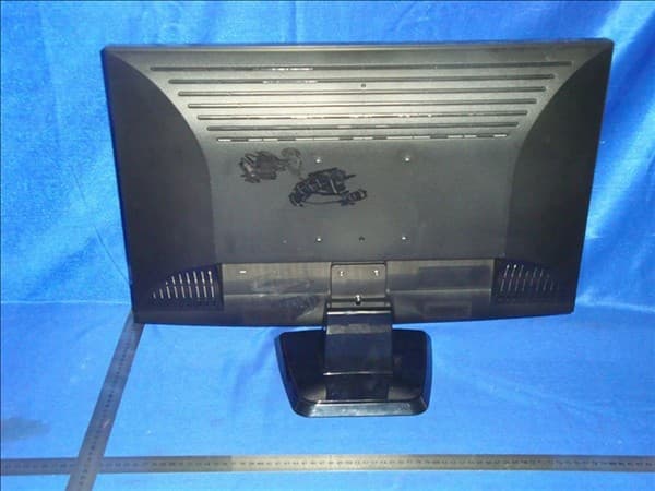
Click to zoom
Application Details
- Equipment Class
- JBP - Part 15 Class B Computing Device Peripheral
- Date of Grant
- Mar 17, 2010
- Application Purpose
- Original Equipment
- Date of Application
- Mar 17, 2010
- Equipment Note
- LCD MONITOR
- Country
- China
Documents & Files
Document Text
Text extracted from the exhibit documents filed with the FCC. Open a document above to read the original.
Users Manual
VOL MODE 7 8 resulted from electric shocks and abnormal power supply voltage. Please disconnect the power if the display is not used for a long period so as to prevent damage HF K.:60 V.F:75Hz1024x768 Do not excessively bend the plug and wire nor place heavy objects upon them, which could cause damage. Do not disconnect the power cord while using the monitor. Keep the plastic packaging (bag) out of children’s reach. Do not insert metal objects such as chopsticks, wire and gimlet or inflammable objects such as paper and match into the vent, headphone port or AV ports or etc. When viewing a fixed screen for an extended period of time, residual image or blurriness may appear. Change the mode to energy saving mode or set a screensaver to a changing picture when away from the monitor for an extended period of time. When viewing a fixed screen for an extended period of time, residual image or blurriness may appear. Be sure to contact an authorized Service Center, when installing your monitor in a location with heavy dust, high or low temperatures, high humidity, and exposed to chemical substances and where it operates for 24 hours such as at airports, train stations etc.Failure to do so may cause serious damage to your monitor. ,benzene. Make sure to unplug the power cord before cleaning the product. may damage the displa. The display shall be dusted off periodically with a piece of clean soft cloth to keep clean. Any fluid OSD Shortcut Key Optimal Screen Resolution Settinge Menu Safety Precautions Environmental considerations Cleaning and Maintenance of LCD Uniformity and related compliance Trouble shooting Operation of display How to use on screen display(OSD) Connection of display to PC Inside the box Unique feature introduction or oror or or or or or or or or or or or or VOLkeyVOL 7 8 MODEkeyMODE 50 F 104 F(10 C 40 C) -4 113 -20 45FF(CC) 10% 80%,non-condensing 585%%,non-condensing Displaying volume control bar Displaying brightness window display mode Manual screw slightly slightly slightly slightly Adjust the brightness of the Power LED brightnessLED
Cover Letter(s)
DATE 2010-03-17 Equipment Autorisation Division Federal Communications Commission 7435 Oakland Mills Road Columbia, MD 21046 FCC ID:KXYM236XXX Product Name:Monitor Request for Confidentiality Pursuant to Sections 0.457 and 0.459 of the commissions rules, we hereby request that the following documents be held confidential: (List here the documents for which you are seeking confidentiality – for example ...) Schematics Block diagram These materials contain trade secrets and proprietary information and are not customarily released to the public. The public disclosure of this information might be harmful to the company and provide unjustified benefits to our competitors. Dated this 2010 -03 -17 By: Lin Yu Signature Printed Title: Engineer On behalf of : China Great-Wall Computer Shenzhen Co. Ltd. Telephone: 86-755-26639997
Cover Letter(s)
DATE 2010-03-17 Nemko Canada Inc 303 River Road Ottawa, Ontario, Canada K1V 1H2 Attn: Director of Certification Authority to Act as Agent On our behalf, I appoint , _ Nemko AS Shenzhen Rep.office / RM3010-3011 ,Block A,United Plaza,No.5022 Binhe Road,Futian District,Shenzhen,Guangdong,China /Daria Liu__ (Name and address,person). to act as our agent in the preparation of this application for equipment certification. I certify that submitted documents properly describe the device or system for which equipment certification is sought. I also certify that each unit manufactured, imported or marketed, as defined in the Federal Communications Commission’s regulations will have affixed to it a label identical to that submitted for approval with this application. For instances where our authorized agent signs the application for certification on our behalf, I acknowledge that all responsibility for complying with the terms and conditions for certification, as specified by Nemko Canada Inc, still resides with_( China Great-Wall Computer Shenzhen Co. Ltd. / Science & Industry Park Shenzhen,Guangdong,China/Linyu)_ ( applicant name and address). Dated this 2010 03 17 Agency agreement expiration date: Usually Give 8 - 12 Months By: Lin Yu Signature Printed Title: Engineer On behalf of : China Greatwall computer Shenzhen Co.,ltd Telephone: 86-755-26639997
External Photos
IEC 60950-1 (ed.2) - Page 1 of 7 - Photos www.nemko.com Report No.
Internal Photos
IEC 60950-1 (ed.2) - Page 2 of 7 - Photos www.nemko.com Report No. IEC 60950-1 (ed.2) - Page 3 of 7 - Photos www.nemko.com Report No. IEC 60950-1 (ed.2) - Page 4 of 7 - Photos www.nemko.com Report No. IEC 60950-1 (ed.2) - Page 5 of 7 - Photos www.nemko.com Report No. IEC 60950-1 (ed.2) - Page 6 of 7 - Photos www.nemko.com Report No. IEC 60950-1 (ed.2) - Page 7 of 7 - Photos www.nemko.com Report No.
Operational Description
When the computer signal get into the LCD monitor from the signal cable and through the VGA and DVI, it get into the main IC .And the Main IC begin to decode, and transform it to LVDS signal to drive relevant LVDS LCD panel. And in the LCD panel, through LCD conversing the two type state, LCD can control the different lights to pass the panel glass or to be obstructed from the panel glass, and so LCD can control the intensity of the lights. And then LCD can combine the 3 color and complete to revert the color and graphics came from the computer. And LCD monitor have no any radio wave producing set and electropult, so there is no expert frequency determing circuit, frequency stabilizing circuit, frequency multiplication stage, and modulator circuit, and the circuits for accomplishing the analogy function herebefore are same . and all the input frequency are same ,and also output frequency are same and clock method and data rate method are same .
Test Report
China Great Wall Computer Shenzhen Co., Ltd. Page 1 of 35 FCCID:KXYM236XXX Reference No.: 142597 FCC Test Report FCC EVALUATION REPORT FOR VERIFICATION Project Reference No. 142597 Product LCD Monitor Brand Name 1) Great Wall, 2) ativa, 3) MECER Model M236JU Alternate Model M236XXX Tested according to FCC Rules and Regulations Part 15 Subpart B Class B 2007, ANSI C63.4-2003 Tested in period 2010-01-16 to 2010-02-24 Issued date 2010-02-24 Name and address of the Test House Nemko Shanghai Ltd. 9A No. 528 Ruiqing Road, PuDong New Area, Shanghai, China P.C. Phone : +86 21 5072 0988 Fax : +86 21 5072 0950 Tested by 2010-02-24 Susan Zhou date Verified by 2010-02-24 Daria Liu date This form is only for use by Nemko, or by others according to special agreement with Nemko. The report may be reproduced infull. Partial reproduction may only be made with the written content of Nemko Shanghai. This report applies only to the sample(s) tested. It is the manufacturer’s responsibility to assure the additional production units of this product are manufactured with identical electrical and mechanical components. China Great Wall Computer Shenzhen Co., Ltd. Page 2 of 35 FCCID:KXYM236XXX Reference No.: 142597 Contents of This Report 1. Client Information ...............................................................................................................................3 1.1 Applicant ....................................................................................................................................3 1.2 Manufacturer..............................................................................................................................3 1.3 Scope.........................................................................................................................................3 2. Equipment under Test (EUT)..............................................................................................................4 2.1 Identification of EUT ..................................................................................................................4 2.2 Model List...................................................................................................................................4 2.3 Setup drawing ............................................................................................................................4 2.4 Additional Information Related to Testing ..................................................................................4 2.5 Picture Documentation ..............................................................................................................4 3. General Test Conditions......................................................................................................................5 3.1 Location .....................................................................................................................................5 3.2 Operating Environment..............................................................................................................5 3.3 Operating During Test ................................................................................................................5 3.4 Test Equipment ..........................................................................................................................5 4. Measurement Uncertainty ...................................................................................................................7 5. Conducted Emission (150 KHz to 30 MHz) ...................................................................................8 5.1 Test Procedure...........................................................................................................................8 5.2 Measurement Equipment...........................................................................................................8 5.3 Test Result .................................................................................................................................8 5.3.1 Diagram 001 ..................................................................................................................................9 5.3.2 Diagram 002 ................................................................................................................................10 5.3.3 Diagram 003 ................................................................................................................................ 11 5.3.4 Diagram 004 ................................................................................................................................12 6. Radiated Electromagnetic Disturbances...........................................................................................13 6.1 Test Procedure.........................................................................................................................13 6.2 Measurement Equipment.........................................................................................................13 6.3 Test Result ...............................................................................................................................13 6.3.1 Diagram 005 ................................................................................................................................15 6.3.2 Diagram 006 ................................................................................................................................16 6.3.3 Diagram 007 ................................................................................................................................17 6.3.4 Diagram 008 ................................................................................................................................18 6.3.5 Diagram 009 ................................................................................................................................19 6.3.6 Diagram 010 .........…
Text truncated - open the document above for the full version.
Test Setup Photos
C.1 Conducted Emission of EUT Front Side C.2 Radiated Emission of EUT below 1GHz Front Rear C.3 Radiated Emission of EUT above 1GHz
Contact Information
Applicant
Lin Yu(Engineer)
86-755-663-9997
Technical Contact
China Great-Wall Computer Shenzhen Co. Ltd.Liu Zhi Guo
[email protected]86-755-2663-9997
Science & Industry Park · Shenzhen · China
Non-Technical Contact
China Great-Wall Computer Shenzhen Co. Ltd.Liu Zhi Guo
[email protected]86-755-2663-9997
Test Firm
Nemko Shanghai Ltd.Zhou Suxia
Technical Specifications
| # | Rule Parts | Frequency Range | Power Output |
|---|---|---|---|
| 1 | 15B | - | - |
Other Applications from China Great-Wall Computer Shenzhen Co. Ltd.
KXY-A892
Dec 09, 2010NOTEBOOK COMPUTER-WLAN PORTION
Equipment Class
DTS - Digital Transmission System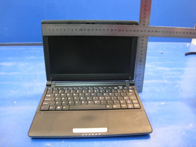
KXYA86
Mar 27, 2010Notebook Computer
Equipment Class
DTS - Digital Transmission System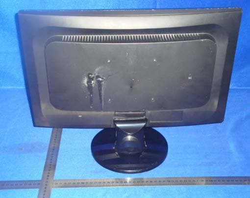
KXYM20DXXX
Jan 18, 2010LCD MONITOR
Equipment Class
JBP - Part 15 Class B Computing Device Peripheral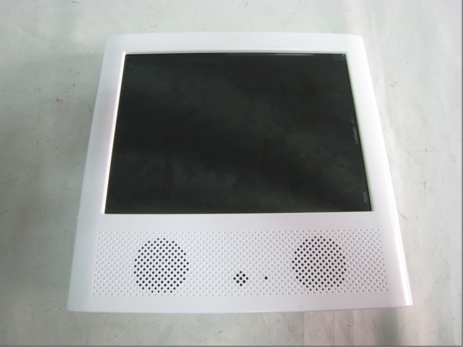
KXYPF8400
Jan 05, 2010PART 15 CLASS B COMPUTING DEVICE PERIPHERAL
Equipment Class
JBP - Part 15 Class B Computing Device Peripheral
KXYL2632XXXXD
Dec 20, 2007LCD TV
Equipment Class
JBP - Part 15 Class B Computing Device Peripheral