KXYL2632XXXXALCD Colour TV
China Great-Wall Computer Shenzhen Co. Ltd.
Click to zoom
Application Details
- Equipment Class
- JBP - Part 15 Class B Computing Device Peripheral
- Date of Grant
- Dec 17, 2007
- Application Purpose
- Original Equipment
- Date of Application
- Dec 17, 2007
- Equipment Note
- LCD Colour TV
- Country
- China
Documents & Files
Document Text
Text extracted from the exhibit documents filed with the FCC. Open a document above to read the original.
Users Manual
MODEL: L26GAM4 L32GAM4 All the illustrations inside the manual and the product accessories provided are for reference only. the package may vary. The company reserves the right to change the bundled accessories without prior notice. The actual content of 1 Don't place the TV set on the unstable surface to prevent it from falling off . sunlight cables and should be avoided filled such when it is left unused for a long time. shut down the TV temporarily. unplug the power cable from wall outlet. no signal input detected no signal input detected 1.When using a PC as the signal source, please adjust the resolution of the graphic card to one of the following recommended resolutions: 1.Any settings changed when the TV is in operation will be saved before the TV is shut down and be applied to next operation. Memorization of changed settings before TV shuts down 1.Please connect the TV's power cable to the a wall outlet with AC 100~240V only. Out of spec power supply may overload the device and cause damage to it. 2.If the screen of the TV is not on after you have plugged the power cable to an electric outlet , press the power button on the remote control or on the TV. please do not place it in an airtight place and avoid covering its vents to ensure good ventilation. If your TV is broken or damaged, please contact your place of purchase or the local service center for help instead of repairing it by yourself to prevent any personal danger. unplug the power and antenna cables. 2 3 1 12 1 18 19 Supported operating modes 22 8 8 9 14 21 21 AC POWER Blue Red 4 In operation for 5 Y PbPr2 Y PbPr1 Y PbPr2 Y PbPr1 SOURCE SLEEP Press to set a preset time interval for automatic shutdown. Press to switch size (4:3, 16:9,) AUTO Under VGA mode, the screen position could be auto matically adjusted by pressing “Auto” button, when the screen image is slanted. MTS Press to select from SAP, Mono or Stereo mode. NR Press to select noise reduction function Return to previous channel Press to display the information of current channel number and time Press to scroll through all available program channels. CH and CH Press to adjust volume. VOL and VOL Press to show the on screen display menu. V-CHIP Press to v-chip function 1 2 4 3 5 9 8 7 6 10 11 12 1413 17 15 19 16 18 6 channels Do not mix old or us- ed batteries with new ones. dead 7 8 the end of antenna or cable TV network quality of displayed pict- dedicated Coaxial cable. Otherwise,ther re should be plugged into the 75Ohm coaxial connector which locates on the rear of TV set In order to receive TV programs transmitted by satellite, a sate- llite receiver should be connected to the rear of the lcd tv. Mean while, in order to receive encoded signal, a decoder should be connected to the rear of lcd tv. Connect the coaxial(AV or Component) cable connectors to TV Satellite/Cable Receiver for a DVD player Y PbPr1 Supported Y PbPr1 Y PbPr2 Y PbPr2 Y PbPr Y PbPr Supported 9 10 Picture Mode Set Brightness Set Contrast Set 11 Saturation Set Sharpness Set Hue Set
Users Manual
12 Sound Mode Set Volume Set 13 Bass Set Treble Set Balance Set CC Parent Guide CC Parent Guide CC Parent Guide 14 Language Set Blue Back Set Timer Set Timer Set CC Parent Guide CC Parent Guide off/CC1/CC2/CC3/CC4/TT1/TT2/TT3/TT4 Function. Press the“VOL ” button on the remote control to enter the “Change password” menu. Movie Rating English Rating TV Rating V-CHIP Change Password French Rating None Exempt Exempt Press the“MENU” button on the remote control to return to upper menu. 4. Press “CH /CH ” button to select “V-CHIP”and press “VOL /VOL ” button to select On/Off. 5. Press the“VOL ” button on the remote control to enter the “Parent Guide” menu, then press“CH / CH ”button to select“TV Rating”. Movie Rating English Rating TV Rating V-CHIP Change Password French Rating None Exempt Exempt Press the“VOL ” button on the remote control to enter the “TV Rating” menu, Press the“VOL CH ” to select the TV rating, Press the“V-CHIP”button on the remote control to block rating. 4. U UU Press the“MENU” button on the remote control to return to upper menu. 5. 15 Note: CC 功能可使用遥控器上CC键实现,当使用TV AV、S-VIDEO信号源时,可选此项功能。 CC Set Parent Guide Set Movie Rating English Rating TV Rating V-CHIP Change Password French Rating None Exempt Exempt Movie Rating Movie Rating English Rating English Rating TV Rating TV Rating V-CHIP V-CHIP Change Password Change Password French Rating French Rating None None Exempt Exempt Exempt Exempt 16 CC Parent Guide Reset Set 17 Movie Rating Set Password Set TV Rating Set English Rating Set French Rating Set Note: Skip Air/Cable Fine Tune Auto Tune Off Air Skip Air/Cable Fine Tune Auto Tune Off Air Skip Air/Cable Fine Tune Auto Tune Off Air Skip Air/Cable Fine Tune Auto Tune Off Air 18 begin scanning. Note: After the scan is finished, the channels found will be saved automatically. If you want you exit the Auto Ch Search during the Auto search process, press MENU twice to exit. Auto Tune Set Fine Tune Set Air/Cable Set Skip Set Advance 3D NR OSD Transparence OSD Duration Advance 3D NR 3D NR OSD Transparence OSD Transparence OSD Duration OSD Duration Advance Advance 19 Scale Set 3D NR Set Color Temp Set 3D NR OSD Transparence OSD Duration Advance OSD Transparence Set 20 Advance 3D NR OSD Transparence OSD Duration Advance switch to desired signal source. OSD Duration Set 21 Please read the following trouble-shooting first when your TV stops working. If no improvement is made after that, please contact the maintenance center for help. control remote control Check the batteries' contact with the polarities of b This device complies with Part 15 of the FCC Rules. Operation is subject to the following two conditions: (1) this device may not cause harmful interference, and (2) this device must accept any interference received, including interference that may cause undesired operation. Changes or modifications not expressly approved by the party responsible for compliance could void the user's authority to operate the equipment. NOTE: This equipment has been tested and found to comply with the limits for a Class B digital device, pursuant to Part 15 of the FCC Rules. These limits are designed to provide reasonable protection against harmful interference in a residential installation. This equipment generates, uses and can radiate radio frequency energy and, if not installed and used in accordance with the instructions, may cause harmful interference to radio communications. However, there is no guarantee that interference will not occur in a particular installation. If this equipment does cause harmful interference to radio or television reception, which can be determined by turning the equipment off and on, the user is encouraged to try to correct the interference by one or more of the followingmeasures: -- Reorient or relocate the receiving antenna. -- Increase the separation between the equipment and receiver. -- Connect the equipment into an outlet on a circuit different from that to which the receiver is connected. -- Consult the dealer or an experienced radio/TV technician for help. attery compartment. FCC Rules Component Video(YPbPr) Input MODERESOLUTION 480i720X480 480p720X480 576i720X576 576p720X576 720p1280X720 1080i1920X1080 PC-RGBinputPC-RGBinput HDMI Input MODE RESOLUTION 480i720X480 480p720X480 576i720X576 576p720X576 720p1280X720 1080i 1920X1080 PC-VGA Input MODE RESOLUTION HORIZONTALFREQUENCY(KHz) VERTICALFREQUENCY(Hz) DOS720X40031.5070.00 VGA640X48031.5037.90/37.5060.00/72.00/75.00 SVGA800X60037.90/47.20/46.9060.00/72.00/75.00 XGA1024X76848.40/56.50/60.0060.00/70.00/75.00 22 Supported operating modes MADE IN CHINA
Attestation Statements
26” LCD TV MODEL 1.Great Wall L26**** The symbol * can be alphanumeric character or blank. The first and second "*"denote different ornament and/or enclosure and the third and fourth "*" denote different colour of enclosure, client or different sales area 2.SOYO MT-****T26**** **: 1st & 2nd * can be alphanumeric character or blank which represent the abbreviation of the brand name. **: 3rd & 4th * can be alphanumeric character or blank which represent the abbreviation of the name of the manufacturer. **: 5th & 6th * can be alphanumeric character or blank which represent porduct model number. **: 7th & 8th * can be alphanumeric character or blank which represent product specification. 3.PRIVE MT-****T26**** **: 1st & 2nd * can be alphanumeric character or blank which represent the abbreviation of the brand name. **: 3rd & 4th * can be alphanumeric character or blank which represent the abbreviation of the name of the manufacturer. **: 5th & 6th * can be alphanumeric character or blank which represent porduct model number. **: 7th & 8th * can be alphanumeric character or blank which represent product specification. 32 1.Great Wall L32**** The symbol * can be alphanumeric character or blank. The first and second "*"denote different ornament and/or enclosure and the third and fourth "*" denote different colour of enclosure, client or different sales area 2.SOYO MT-****T32**** **: 1st & 2nd * can be alphanumeric character or blank which represent the abbreviation of the brand name. **: 3rd & 4th * can be alphanumeric character or blank which represent the abbreviation of the name of the manufacturer. **: 5th & 6th * can be alphanumeric character or blank which represent porduct model number. **: 7th & 8th * can be alphanumeric character or blank which represent product specification. 3.PRIVE MT-****T32**** **: 1st & 2nd * can be alphanumeric character or blank which represent the abbreviation of the brand name. **: 3rd & 4th * can be alphanumeric character or blank which represent the abbreviation of the name of the manufacturer. **: 5th & 6th * can be alphanumeric character or blank which represent porduct model number. **: 7th & 8th * can be alphanumeric character or blank which represent product specification.
Block Diagram
HD MI VGA AV 2 CV BS AV 1 CV BS YP BP R S - VI DE O SC AR T KE Y IR FL AS H LE D E2 P R OM LV DS T P A 300 8D 2 I NNE R Y/C 40 52 EX T A UDI O PI 5V 33 0 I N N E R Y/ C AU DI O A VOU T PC AUD IO AV 2 AUD IO AV 1 AUD IO SP EA KE R PA NE L SCART OUT SCART AUDIO
Cover Letter(s)
stgnature .^..+-.*w. Title: R&D Manager
Cover Letter(s)
China greatwall computer Shenzhen Co.,Ltd Dec.15,2007 To whom it may concern, Request for Short-term Confi dentiality FCCtr):KXYL2632xxxxA Request is hereby submitted by China greatwall computer Shenzhen Co.,Ltd to withhold from public review for a period of 45 days from the date of the Grant of Equipment Authorization and prior to marketing,certain porions of the application for equipment certification for the referenced FCC identifiers.This request for confidentialiy is made pursuant to 47CFR0.457(d) and 0.459 of FCC Rules. In particular, the following sections of the application are to be kept confidential for a period of 45 days from the date ofAuthorization: I Schematics 2 Block Diagram 3 Extemal photos 4 Inemal photos The ratisnale for rsquest for confidentiality is as followings: The above referenced product is subject to competition. China greatwall computer Shenzhen Co.rltd has invested considerable time and materials in research and development to produce the referenced product. Disclosure of the short-term confidential portions of this application during the period of importation and/or distribution would reveal key aspects of proprietary technology to competitors and diminish the value of our investment in research and development. Ifyou have questions ofneed further information, please contact the undersigned. R&D Manager
External Photos
Front Back Left Right
ID Label/Location Info
Label location
Internal Photos
Internal photo 1 Internal photo2 Internal photo3 Internal photo4 Internal photo5 Internal photo6 Internal photo 7 Internal photo 8 Whole view of EUT
Operational Description
Operation description FUNCTION 26Specifications 32Specifications Model name T260*W03 T315*W02 Screen Size 26” 32” Active Display Area 575.769(H)*323.712(V)697.68(H)*392.26(V) Pixel Pitch 0.4215mm 0.51075mm Max. Resolution 1366(H)*768(V) 1366(H)*768(V) Aspect ratio 16:9 16:9 Contrast Ratio 1200:1 1200:1 Brightness 500cd/m2 500cd/m2 Response Time 8ms 8ms Display Color 16.7M 16.7M Viewing Angle 176° 176° LCD Panel Lamp Life 60000H 60000H TV System NTSC NTSC Sound System M/N M/N Stereo System STEREO/MONO/BTSC/ SAP STEREO/MONO/BTSC/ SAP Video&Audio OSD language English Etc. English Etc. Frequency range V:56-75HZ H:30-80KHZ V:56-75HZ H:30-80KHZ Max Display Mode 1920*1080@60HZ 1920*1080@60HZ Monitor display System Plug&Play YES YES Power supply AC100~240V 50/60HZ AC100~240V 50/60HZ Power consumption 160W 160W Others Stand by power consumption <2W <2W
Test Report
Report No.SZEE071115119702 Page 1 of 17 ELECTROMAGNETIC EMISSIONS COMPLIANCE REPORT UNINTENTIONAL RADIATOR CERTIFICATION TO FCC PART 15 SUBPART B REQUIREMENT OF LCD TV (Analog) CRYSTAL SERIES(Analog) 26”HD READY LCDTV(Analog) 32”HD READY LCD TV(Analog) MODEL No.: SEE ANNEX A BRAND NAME: Great Wall/SOYO/prive FCC ID: KXYL2632°°°°A REPORT NO.: SZEE071115119702 ISSUE DATE: December 18, 2007 Prepared for CHINA GREAT WALL COMPUTER SHENZHEN CO.,LTD GREATWALL BUILDING,SCIENCE&INDUSTRIAL PARK,NANTOU,SHENZHEN,CHINA TEL: 86-755-2663 9997 FAX: 86-755-2762 2394 Prepared by CENTRE TESTING INTERNATIONAL 1F., BUILDING C,HONGWEI INDUSTRIAL ZONE, BAOAN 70 DISTRICT, SHENZHEN, CHINA TEL: 86-755-3368 3668 FAX: 86-755-3368 3385 This report shall not be reproduced, except in full, without the written approval of CENTRE TESTING INTERNATIONAL Report No.SZEE071115119702 Page 2 of 17 VERIFICATION OF COMPLIANCE Applicant: CHINA GREAT WALL COMPUTER SHENZHEN CO.,LTD GREATWALL BUILDING,SCIENCE&INDUSTRIAL PARK,NANTOU,SHENZHEN,CHINA Product Name: LCD TV (analog)/CRYSTAL SERIES(analog) 26”HD READY LCDTV(analog)/32”HD READY LCD TV(analog) Brand Name: Great Wall/ SOYO/prive Model Number: See annex A Serial Number: N/A File Number: SZEE071115119702 Date of Test: November 20,2007 ~ December 16 , 2007 We hereby certify that: The above equipment was tested by Centre Testing International (CTI), The test data, data evaluation, test procedures, and equipment configurations shown in this report were made in accordance with the procedures given in ANSI C63.4 (2003) and the energy emitted by the sample EUT tested as described in this report is in compliance with conducted and radiated emission limits of FCC Rules Part 15B The test results of this report relate only to the tested sample identified in this report. Approved By Manager CENTRE TESTING INTERNATIONAL Report No.SZEE071115119702 Page 3 of 17 TABLE OF CONTENTS Description Page 1. GENERAL INFORMATION .................................................................................................. 4 1.1 PRODUCT DESCRIPTION........................................................................................................................4 1.2 MODEL INFORMATION.........................................................................................................................5 1.3 TEST METHODOLOGY...........................................................................................................................5 1.4 TEST FACILITY.....................................................................................................................................5 1.5 SPECIAL ACCESSORIES........................................................................................................................5 1.6 EQUIPMENT MODIFICATIONS..............................................................................................................5 2. SYSTEM TEST CONFIGURATION ..................................................................................... 6 2.1 EUT CONFIGURATION.........................................................................................................................6 2.2 EUT EXERCISE....................................................................................................................................6 2.3 TEST PROCEDURE.................................................................................................................................6 2.4 LIMITATION..........................................................................................................................................7 2.5 ANTENNA CONDUCTED EMISSION........................................................................................................8 3. SUMMARY OF TEST RESULTS .......................................................................................... 9 4. DESCRIPTION OF TEST MODES ....................................................................................... 9 5. CONDUCTED EMISSIONS TEST ........................................................................................ 9 5.1 MEASUREMENT PROCEDURE: ..............................................................................................................9 5.2 TEST SET-UP (BLOCK DIAGRAM OF CONFIGURATION) ......................................................................9 5.3 MEASUREMENT EQUIPMENT USED: ...................................................................................................10 5.4 MEASUREMENT RESULT: ...................................................................................................................10 6. RADIATED EMISSION TEST ............................................................................................. 11 6.1 MEASUREMENT PROCEDURE..............................................................................................................11 6.2 TEST SET-UP (BLOCK DIAGRAM OF CONFIGURATION) ....................................................................11 6.4 FIELD STRENGTH CALCULATION.......................................................................................................12 7. ANTENNA CONDUCTED POWER .................................................................................... 14 7.1 MEASUREMENT PROCEDURE..............................................................................................................14 7.2 TEST SET-UP (BLOCK DIAGRAM OF CONFIGURATION) ....................................................................14 7.3 MEASUREMENT EQUIPMENT USED: ...................................................................................................14 7.4 MEASUREMENT RESULTS:..................................................................................................................14 APPENDIX 1 PHOTOGRAPHS OF SETUP .......................................................................... 15 Report No.SZEE071115119702 Page 4 of 17 1. GENERAL INFORMATION …
Text truncated - open the document above for the full version.
Test Setup Photos
Report No.SZEE071115119702 Page 16 of 17 RADIATED EMISSION TEST SETUP CONDUCTED EMISSION TEST SETUP
Contact Information
Applicant
Lin Yu(Engineer)
86-755-663-9997
Test Firm
Centre Testing InternationalHe Xiaojun
Technical Specifications
| # | Rule Parts | Frequency Range | Power Output |
|---|---|---|---|
| 1 | 15B | - | - |
Other Applications from China Great-Wall Computer Shenzhen Co. Ltd.
KXY-A892
Dec 09, 2010NOTEBOOK COMPUTER-WLAN PORTION
Equipment Class
DTS - Digital Transmission System
KXYA86
Mar 27, 2010Notebook Computer
Equipment Class
DTS - Digital Transmission System
KXYM236XXX
Mar 17, 2010LCD MONITOR
Equipment Class
JBP - Part 15 Class B Computing Device Peripheral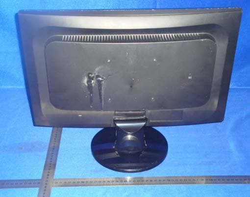
KXYM20DXXX
Jan 18, 2010LCD MONITOR
Equipment Class
JBP - Part 15 Class B Computing Device Peripheral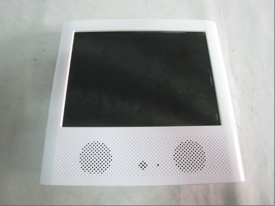
KXYPF8400
Jan 05, 2010PART 15 CLASS B COMPUTING DEVICE PERIPHERAL
Equipment Class
JBP - Part 15 Class B Computing Device Peripheral