KZ3-050259SHIELDS TRANSMITTER
Radio Systems Corporation
Click to zoom
Application Details
- Equipment Class
- DXX - Part 15 Low Power Communication Device Transmitter
- Date of Grant
- Nov 08, 2005
- Application Purpose
- Original Equipment
- Date of Application
- Nov 08, 2005
- Equipment Note
- SHIELDS TRANSMITTER
- Frequency Range
- 0.01070000 - 0.01070000
- Company
- Radio Systems Corporation
- Country
- United States
Documents & Files
Document Text
Text extracted from the exhibit documents filed with the FCC. Open a document above to read the original.
Users Manual
Shields ™ Indoor Avoidance System Owner’s Manual www.invisiblefence.com 800-SAFEDOG Rev 0.2 Draft 2 Invisible Fence ® Brand Titanium Computer Collar ® Unit AC adapter Shields ™ Indoor Avoidance System Components Your Shields ™ Indoor Avoidance System includes the following components: Shields ™ Transmitter The transmitter is the heart of the system. It is placed in areas you want to shield from your pet. The lightweight, portable design is easy to use and powered by a rechargeable battery pack. You may use the included AC adapter for locations near an electrical outlet. The Shields ™ transmitter has three control buttons: Two for controlling the signal field range (RANGE UP & RANGE DOWN) One for use when programming for multiple pets (CHANNEL) The LCD display shows the signal field range and multi-area shielding selections. Invisible Fence ® Brand Titanium Computer Collar ® Unit Worn by your pet, the Titanium Computer Collar ® unit detects areas you have shielded and adminis- ters a “correction”. AC Adapter This is included for long-term use, or as a charger for the rechargeable battery pack. Shields ™ Transmitter NOTE: A correction is a training term used to describe an action taken to discourage unwanted pet behavior. The Computer Collar ® unit applies a correction when your pet enters a shielded area or crosses the boundary of an Invisible Fence ® Brand pet containment system. Corrections are used in combination with rewards to alter unwanted pet behavior. Rev 0.2 Draft 3 T hank you for your purchase of the Shields ™ Indoor Avoidance System. Please read this manual to become familiar with the Shields ™ components and its operation. It is strongly recommended you review this information before using the product. Information About Your Shields ™ Indoor Avoidance System Shields ™ gives you control over the areas a pet or pets have access to inside your home. It is designed to work independently, or to complement your Invisible Fence ® Brand 800 Series outdoor pet containment system. Benefits of the Shields ™ system include: Flexibility : Uses the same Invisible Fence ® Brand Titanium Computer Collar ® unit for both indoor avoidance and outdoor pet con- tainment Port ability: Shields ™ is powered by a rechargeable battery pack. It can be placed virtually anywhere, on chairs, under tables, by the trash, etc. (An AC adapter is included with every Shields ™ system). Adjust able: The Shields ™ system allows you to control the width of the signal field range with the touch of a button. The signal field is the area around the Shields ™ transmitter you want your pet to avoid. The signal field range can be set to a minimum diameter of 2 feet up to a maximum diameter of 12 feet. Customization : The Multi-Area shielding option allows you to choose/change different shielded areas for different pets. For example: You can program one Shields ™ sys- tem to keep pet 1 away from pet 2’s food dish, AND Program a second Shields ™ system to keep both pets away from the trash See the section labeled Shields ™ Multi-Area Usefor detailed instructions. Important Precautions Read and retain manual: Read the entire Owner’s Manual before using your Shields ™ indoor avoidance system. If you have any ques- tions after reading this manual, call your Invisible Fence ® Brand Dealer. Train your pet: Train your pet according to the instructions contained in this manual. Do not become overly confident your pet has become conditioned to the Shields ™ indoor avoidance system sooner than expected. Obey all cautions and warnings: Adhere to all cautions and warnings contained in any Invisible Fence ® Brand manual. Never perform set-up procedures while the Titanium Computer Collar ® unit is on your pet. Use only on pets: All Invisible Fence ® Brand products are designed for pet use only. Never attempt to use this product for any purpose not specifically described in this manual. Check the tightness of the Titanium Computer Collar ® unit on a regular basis: When possible, remove your pet’s Titanium Computer Collar ® unit each night. This will prevent the possibility of any irritation the collar may cause to your pet’s skin. However, if this is not possible, please check the tightness of the collar each time you feed your pet by removing the collar and then replacing it back on your pet. Call for service or repair: Do not attempt to serv- ice any Invisible Fence ® Brand equipment. Refer all service to your authorized Invisible Fence ® Brand Dealer only. Unauthorized service or repair will void the warranty. Dealer Name: _______________________ Dealer Phone: _______________________ Rev 0.2 Draft 4 Q uick Start Guide Shields ™ are powered by the rechargeable battery pack and/or the AC adapter. Use the AC adapter to charge the battery pack overnight prior to first use. 1 1 Power ON a. Turn the Shields ™ transmitter ON by pressing the RANGE UP (+) button. b. A segmented bar appears in the display. c. To turn the Shields ™ transmitter off, press and release the RANGE DOWN (-) button until the segmented bars do not appear in the display. 2 2 Adjust signal field range a. Determine the desired location and the signal field range required (2 feet mini- mum diameter up to a 12 feet maximum diameter). b. With the unit on, press the RANGE UP (+) or the RANGE DOWN (-) buttons to increase or decrease the signal field range. c. Each segment of displayed bar repre- sents approximately 2 feet diameter of range. d. Once the range is set, place the Shields ™ transmitter in the desired area. 3 3 Verify the signal field range a. Make sure the Shields ™ transmitter is on. b. Holding the Titanium Computer Collar ® unit, start outside the range and walk slowly towards the Shields ™ transmitter. c. The Titanium Computer Collar ® unit will beep as it approaches the outer range of the signal field width set in step 2. The beeping will be followed by a cor- rection. d. If the Titanium Computer Collar ® unit fails to beep, see the troubleshooting chart found…
Text truncated - open the document above for the full version.
External Photos
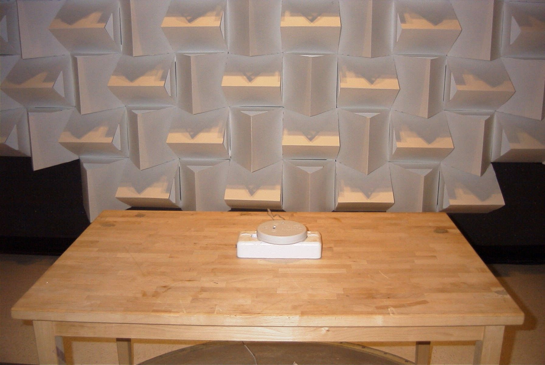
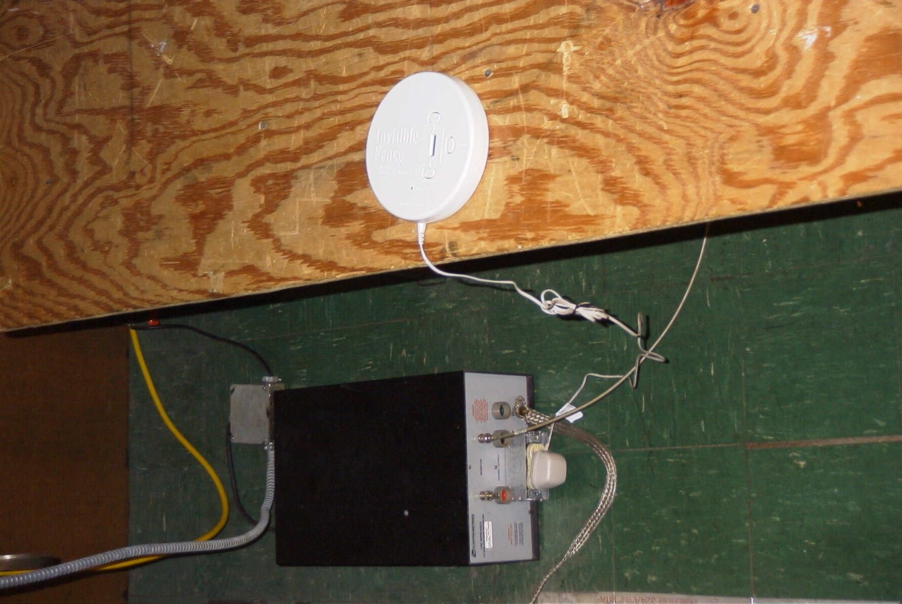
Invisible Fence, Shields External Photos EUT Front Invisible Fence, Shields External Photos EUT Rear Invisible Fence, Shields External Photos EUT Side Invisible Fence, Shields External Photos Power supply
ID Label/Location Info
Invisible Fence, Shields label location Label location, label will be installed using permanent adhesive. Photo for location information only, please see label sample for text.
Internal Photos
Invisible Fence, Shields Internal Photos PCB Component Side Invisible Fence, Shields Internal Photos PCB Solder Side
Test Report
TIMCO ENGINEERING INC. 849 NW State Road 45 Newberry, Florida 32669 http://www.timcoengr.com 888.472.2424 F 352.472.2030 email: [email protected] APPLICANT: INVISIBLE TECHNOLOGIES, INC. FCC ID: KZ3-050259 Test Report Product Name: 10.7KHz SHIELD TRANSMITTER FCC ID: KZ3-050259 Applicant: INVISIBLE TECHNOLOGIES, INC. 1000 Fuller Drive Garrett IN. 46738 USA Date Receipt: 10/19/2005 Date Tested: 10/19/2005 REPORT #: I\INVISIBLE\2137AUT5\2137AUT5TestReport.doc COVER SHEET TIMCO ENGINEERING INC. 849 NW State Road 45 Newberry, Florida 32669 http://www.timcoengr.com 888.472.2424 F 352.472.2030 email: [email protected] APPLICANT: INVISIBLE TECHNOLOGIES, INC. TABLE OF CONTENTS APPLICANT: INVISIBLE TECHNOLOGIES, INC. FCC ID: KZ3-050259 REPORT CONTAINING: PAGE 1-5...........TEST EQUIPMENT LIST PAGE 6.............TEST PROCEDURE PAGE 7-8...........RADIATION INTERFERENCE TEST DATA PAGE 9.............OCCUPIED BANDWIDTH PAGE 10............OCCUPIED BANDWIDTH PLOT EXHIBITS INCLUDING: BLOCK DIAGRAM SCHEMATIC LABEL SAMPLE LABEL LOCATION PARTS LIST INSTRUCTION MANUAL FCC ID: KZ3-050259 REPORT #: I\INVISIBLE\2137AUT5\2137AUT5TestReport.doc TABLE OF CONTENTS TIMCO ENGINEERING INC. 849 NW State Road 45 Newberry, Florida 32669 http://www.timcoengr.com 888.472.2424 F 352.472.2030 email: [email protected] APPLICANT: INVISIBLE TECHNOLOGIES, INC. EMC Equipment List Device Manufacturer Model Serial Number Cal/Char Date Due Date 3/10-Meter OATS TEI N/A N/A Listed 3/27/04 3/26/07 3-Meter OATS TEI N/A N/A Listed 1/13/03 1/12/06 Biconnical Antenna Eaton 94455-1 1057 CAL 3/18/03 3/18/05 Biconnical Antenna Eaton 94455-1 1096 CAL 8/17/04 8/17/06 Biconnical Antenna Electro- Metrics BIA-25 1171 CAL 4/29/05 4/29/07 Blue Tower Quasi-Peak Adapter HP 85650A 2811A01279 CAL 4/13/05 4/13/07 Blue Tower RF Preselector HP 85685A 2926A00983 CAL 8/3/05 8/3/07 Blue Tower Spectrum Analyzer HP 8568B 2928A04729 2848A18049 CAL 4/13/05 4/13/07 LISN Electro- Metrics ANS-25/2 2604 CAL 8/27/04 8/27/06 LISN Electro- Metrics EM-7820 2682 CAL 4/28/05 4/28/07 Log- Periodic Antenna Eaton 96005 1243 CAL 5/8/03 5/8/05 FCC ID: KZ3-050259 REPORT #: I\INVISIBLE\2137AUT5\2137AUT5TestReport.doc Page 1 of 10 TIMCO ENGINEERING INC. 849 NW State Road 45 Newberry, Florida 32669 http://www.timcoengr.com 888.472.2424 F 352.472.2030 email: [email protected] APPLICANT: INVISIBLE TECHNOLOGIES, INC. TEST PROCEDURES GENERAL: This report shall NOT be reproduced except in full without the written approval of TIMCO ENGINEERING, INC. RADIATION INTERFERENCE: The test procedure used was ANSI STANDARD C63.4-2003 using a HEWLETT PACKARD spectrum analyzer with a pre-selector. In the frequency range 10 kHz to 30 MHz the RBW was 10 kHz and from 30-1000 MHz the RBW of the spectrum analyzer was 100 kHz with an appropriate sweep speed. The analyzer was calibrated in dB above a microvolt at the output of the antenna. The resolution bandwidth was 100 kHz and the video bandwidth was 300 kHz. The ambient temperature of the UUT was &tempr& with a humidity of &humr&. FORMULA OF CONVERSION FACTORS: The Field Strength at 3m was established by adding the meter reading of the spectrum analyzer (which is set to read in units of dBuV) to the antenna correction factor supplied by the antenna manufacturer. The antenna correction factors are stated in terms of dB. The gain of the Pre-selector was accounted for in the Spectrum Analyzer Meter Reading. Example: Freq (MHz) METER READING + ACF = FS 33 20 dBuV + 10.36 dB = 30.36 dBuV/m @ 3m ANSI C63.4-2003 Section 8.2.1 MEASUREMENT PROCEDURES: The EUT was placed on a non-conducting table 80 cm above the ground plane with the EUT located in the center of the table. With the antenna vertical a preliminary scan was done at 1 meters distance, the EUT was moved to a 3.0-meter distance and the antenna height varied and also placed in a horizontal position. The frequency was scanned from 9.0 kHz to 1.0 GHz. When an emission was found, the table was rotated to produce the maximum signal strength. The EUT was measured in three (3) orthogonal planes. The unit was measured at TIMCO ENGINEERING, INC. located at 849 N.W. State Road 45 Newberry, Florida 32669. FCC ID: KZ3-050259 REPORT #: I\INVISIBLE\2137AUT5\2137AUT5TestReport.doc Page 2 of 10 TIMCO ENGINEERING INC. 849 NW State Road 45 Newberry, Florida 32669 http://www.timcoengr.com 888.472.2424 F 352.472.2030 email: [email protected] APPLICANT: INVISIBLE TECHNOLOGIES, INC. APPLICANT: INVISIBLE TECHNOLOGIES, INC. FCC ID: KZ3-050259 NAME OF TEST: RADIATION INTERFERENCE RULES PART NO.: 15.109(a) and 15.209 REQUIREMENTS: CARRIER FREQUENCY WILL NOT EXCEED 2400/F (kHz) AT 300 METERS OUT-OF-BAND EMISSIONS SHALL NOT EXCEED THE LEVEL OF THE FUNDAMENTAL. 9 to 490 KHz: 2400/F (kHz) uV/m @ 300 METERS 490 to 1705 KHz: 24000/F (kHz) uV/m @ 30 METERS 1705 to 30 MHz: 29.54 dBuV/M @ 30 METERS 30 to 88 MHz: 40.00 dBuV/M @ 3 METERS 88 to 216 MHz: 43.50 dBuV/M 216 to 960 MHz: 46.02 dBuV/M ABOVE 960 MHz: 54.00 dBuV/M TEST CONFIGURATION: The INTENTIONAL RADIATOR was connected to a keyed switch and a harness simulator cable box. The device was tested in both transmitting modes. TEST DATA FUNDAMENTAL: Emission Frequency MHz Meter Reading dBuV Ant. Polarity Coax Loss dB Electric Antenna Factor dB Field Strength dBuV/m Margin dB 0.0107 13.3 V 0 85.9 99.2 27.8 FCC ID: KZ3-050259 REPORT #: I\INVISIBLE\2137AUT5\2137AUT5TestReport.doc Page 3 of 10 TIMCO ENGINEERING INC. 849 NW State Road 45 Newberry, Florida 32669 http://www.timcoengr.com 888.472.2424 F 352.472.2030 email: [email protected] APPLICANT: INVISIBLE TECHNOLOGIES, INC. APPLICANT: INVISIBLE TECHNOLOGIES, INC. FCC ID: KZ3-050259 NAME OF TEST: RADIATION INTERFERENCE TEST DATA HARMONICS: Emission Frequency MHz Meter Reading dBuV Ant. Polarity Coax Loss dB Correction Factor dB Field Strength dBuV/m Margin dB 32.39 14.5 H 0.41 12.99 27.9 12.1 33.29 16.5 V 0.42 11.15 28.07 11.93 34 19.3 V 0.42 10.88 30.6 9.4 43.88 23 H 0.47 11.24 34.71 5.29 45.36 18.09 V 0.48 10.17 28.74 11.26 45.68 11.3 H…
Text truncated - open the document above for the full version.
Contact Information
Applicant
Clifton P Brick
Test Firm
Timco Engineering, Inc.Bruno Clavier
Technical Specifications
| # | Rule Parts | Frequency Range | Power Output |
|---|---|---|---|
| 1 | 15C | 0.0107 MHz - 0.0107 MHz | - |
Other Applications from Radio Systems Corporation

KZ3-050808
Apr 25, 2007Safe Dog Monitor/ Dialer Transceiver System
Equipment Class
DXT - Part 15 Low Power Transceiver, Rx Verified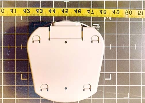
KZ3050241
Mar 28, 2002M024100 Transmitter
Equipment Class
DCD - Part 15 Low Power Transmitter Below 1705 kHz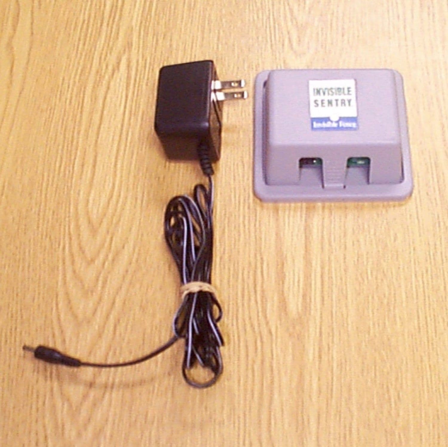
KZ3SENTRY
Aug 08, 2000Invisible Sentry TX: Pet Contaiment Device
Equipment Class
DXX - Part 15 Low Power Communication Device TransmitterKZ3IFA12
Jan 13, 1997Pet Containment Transmitter
Equipment Class
DCD - Part 15 Low Power Transmitter Below 1705 kHzKZ3ICT250
Apr 11, 1996Pet Containment System Transmitter
Equipment Class
DCD - Part 15 Low Power Transmitter Below 1705 kHz