KZ3050241M024100 Transmitter
Radio Systems Corporation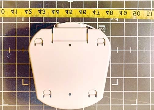
Click to zoom
Application Details
- Equipment Class
- DCD - Part 15 Low Power Transmitter Below 1705 kHz
- Date of Grant
- Mar 28, 2002
- Application Purpose
- Original Equipment
- Date of Application
- Mar 28, 2002
- Equipment Note
- M024100 Transmitter
- Frequency Range
- 0.00819200 - 0.01320000
- Company
- Radio Systems Corporation
- Country
- United States
Documents & Files
Document Text
Text extracted from the exhibit documents filed with the FCC. Open a document above to read the original.
Users Manual
Invisible Fence ® I n s t a l l - I t - Yo u r s e l f Pet Containment S y s t e m I F - 1 0 0 Operation Guide Thank you for purchasing the IF-100 Premium Containment System. This electronic dog containment system is among the s a fest, most humane and effe c t i ve training products yo u can bu y. Once your dog is properly trained, he will enjoy hours of freedom within his new boundari e s, and you will e n j oy the comfo rt of knowing that he has learned to stay s a fely in your ya r d . Please take a few minutes to read the instruction manu a l p rior to your first use and retain the manual for future refe r- e n c e. This instruction manual contains important progra m- ming and set-up info rmation to help your training proceed as successfully as possibl e. For best results, fo l l ow these i m p o rtant ru l e s : I M P O R TANT SAFEGUARDS 1.Obey all warnings contained in this manual. 2.The electronic dog collar is intended only for use on dogs. Never attempt to use this product for any purpose not specifi- cally described in this manual. 3.If you have any reason to believe that your dog may pose a danger to others, or that it may harm itself if it is not kept from crossing the IF-100 containment field wire, you should not rely solely on this product to contain your dog. 4.Do not leave the collar on your dog for more than 12 hours per day. 5.Never perform set-up procedures when the collar is on your dog. 6.Never call or pull your dog into the containment field. 7.Keep all system components out of the reach of children. 8.The IF-100 containment system will not contain your dog unless: A.You train your pet as prescribed in the IF-100 training plan (Section 7, pg.15). B.The transmitter is on, connected to the containment loop wire, and producing a signal along the loop wire. C.The IF-100 collar receiver is worn properly by your dog. D.The IF-100 collar receiver is adjusted so that the probes are touching your dog's skin. E.There is an adequate charge on the IF-100 collar receiver battery.Do not use if you suspect the charge is low. F.The 24-volt adapter is plugged into the transmitter and is connected to a 110-volt household outlet. 9.The following precautions should always be taken: A.Never service or install a system or any equipment during a thunder or electrical storm. B.Never install the transmitter where it could be exposed to the elements, doing so will void the manufacturer's warranty. C.Monitor the transmitter periodically to ensure that the unit is operating properly and is producing a signal along the loop wire. D.Always remove your dog's collar receiver before making any adjustments to your IF-100 containment system. E.Use the lowest correction necessary to get the desired behavior. F.Allow your dog to get used to the collar before you begin training.You want your dog to accept the collar as part of a routine, not to associate the collar with the correction. 10.To prevent the elimination of an adequate safe zone in your yard, any adjustments to the field width must be tested prior to using the system with your dog.Once the field width has been set and tested, turning the knob in a clockwise direction will increase the correction zone and may eliminate the safe zone, thus causing correction to be present throughout your entire yard.If you have any questions, please contact invisible Fence at 1-800-688-4364, before using the system with your dog. 11.Read all instructions before using this product.If you have any questions or concerns after reading this information, contact Invisible Fence at 1-800-688-4364. IMPORTANT Realize that because individual dogs have unique tempera- ments, there is no way of knowing how your dog will react to its introduction to this product.For the safety of your dog, initial training should take place using a six foot or retractable leash to keep you in control of the situation.Also realize that an aggres- sive animal could turn against the handler upon receiving the correction.Therefore, if you feel your dog has an aggressive temperament and/or he has a history of aggressive behavior, you should consult a certified animal behaviorist before using this product.Please refer to the Section 5.B.Setting the Transmitter Controls, Section 5.C.Important Notes about the Collar, and Section 6.Tips for Containment Training before pro- ceeding. 1. IMPORTANT NOTICE:This equipment has been tested and found to comply with the limits for a Class B digital device, pursuant to Part 15 of the FCC Rules.These limits are designed to provide reasonable protection against harmful interference in a residential installation.This equipment generates, uses and can radiate radio fre- quency energy and, if not installed and used in accordance with the instructions, may cause harmful interference to radio communications.However, there is no guarantee that interference will not occur in a particular installation.If this equip- ment does cause harmful interference to radio or television reception, which can be determined by turning the equipment off and on, the user is encouraged to try to correct the interference by one or more of the following measures: • Reorient or relocate the receiving antenna. • Increase the separation between the equipment and receiver. • Connect the equipment into an outlet on a circuit different from that to which the receiver is connected. • Consult the dealer or an experienced radio/TV technician for help. Caution:Changes or modifications to any component, not expressly approved by Invisible Fence, Inc., could void the user's authority to operate this equipment. The term "IC:" before the radio certification number only signifies that Industry of Canada technical specifications were met. I N T R O D U C T I O N Your new electronic containment system contains four major components:a wall-mount transmitter, a collar receiver, a lightning/power surge protection module, and boundary wire.The wall-mount transmitter gener- ates an electronic signal that is tr…
Text truncated - open the document above for the full version.
ID Label/Location Info
FCC ID:KZ3050241 Mfr:Invisible Fence,Inc. To charge receiver, place light at this end. 0900037-1 This device complies with Part 15 of the FCC rules. Operation is subject to the following two conditions:(1) this device may not cause harmful interference, and (2) this device must accept any interference received, including interference that may cause undesired operation. M024100 0900037-1_Label 3/21/02 3:53 PM Page 1
Test Report
Page 1 of 41 Report No.: FC02-030A ADDENDUM TO FC02-030 FOR THE M024100 TRANSMITTER FCC PART 15 SUBPART C SECTIONS 15.207, 15.209 AND RSS 210 COMPLIANCE DATE OF ISSUE: MARCH 27, 2002 PREPARED FOR: Invisible Fence Company, Inc. 355 Phoenixville Pike, Rd #6 Malvern, PA 19355 PREPARED BY: Mary Ellen Clayton CKC Laboratories, Inc. 5473A Clouds Rest Mariposa, CA 95338 P.O. No.: 57897 W.O. No.: 78516 Date of test: March 12-13, 2002 Report No.: FC02-030A This report contains a total of 41 pages and may be reproduced in full only. Partial reproduction may only be done with the written consent of CKC Laboratories, Inc. The results in this report apply only to the items tested, as identified herein. Page 2 of 41 Report No.: FC02-030A TABLE OF CONTENTS Administrative Information .........................................................................................................4 Summary of Results.....................................................................................................................5 Conditions for Compliance ..........................................................................................................5 Approvals.....................................................................................................................................5 Equipment Under Test (EUT) Description ..................................................................................6 Eut Operating Frequency .............................................................................................................6 15.31 Number Of Channels .........................................................................................................6 15.33 Frequency Ranges Tested ..................................................................................................6 15.203/6.2.2(o)(e)(2) Antenna Requirements ..............................................................................6 15.205 Restricted Bands ..............................................................................................................6 Equipment Under Test .................................................................................................................7 Peripheral Devices .......................................................................................................................7 Report of Measurements ..............................................................................................................8 Table 1: 15.209/6.2.1 Fundamental ................................................................................8 15.209/6.2.1 Peak Output Power 120V AC ....................................................................9 15.209/6.2.1 Peak Output Power Battery........................................................................10 Table 2: 15.31(e) Voltage Variations..............................................................................11 Table 3: 15.207/6.6 Six Highest Conducted Emission Levels........................................12 Table 4: 15.209/6.2.1 Six Highest Radiated Emission Levels - 9 kHz - 30 MHz ..........13 Table 5: 15.209/6.2.1 Six Highest Radiated Emission Levels - 30 MHz - 1000 MHz ...14 6 dB Bandwidth ..............................................................................................................15 RSS-210 99% Bandwidth ...............................................................................................16 Measurement Uncertainty ............................................................................................................17 EUT Setup....................................................................................................................................17 Correction Factors........................................................................................................................17 Table A: Sample Calculations ........................................................................................17 Test Instrumentation and Analyzer Settings ................................................................................18 Table B: 15.35 Analyzer Bandwidth Settings Per Frequency Range .............................18 Spectrum Analyzer Detector Functions ..........................................................................18 Peak....................................................................................................................18 Quasi-Peak .........................................................................................................19 Average ..............................................................................................................19 EUT Testing.................................................................................................................................19 Mains Conducted Emissions...........................................................................................19 Radiated Emissions.........................................................................................................20 Appendix A: Information about the Equipment Under Test........................................................21 I/O Ports ..........................................................................................................................22 Crystal Oscillators...........................................................................................................22 Printed Circuit Boards ....................................................................................................22 Photograph Showing Mains Conducted Emissions ........................................................23 Photograph Showing Mains Conducted Emissions ........................................................24 Photograph Showing Radiated Emissions ......................................................................25 Photograph Showing Radiated Emissions ..............................................…
Text truncated - open the document above for the full version.
Test Setup Photos
PHOTOGRAPH SHO WING MAINS CONDUCTED EMISSIONS Mains Conducted Emissions - Front View PHOTOGRAPH SHO WING MAINS CONDUCTED EMISSIONS Mains Conducted Emissions - Side View PHOTOGRAPH SHOWING RADIATED EMISSIONS Radiated Emissions - Front View Below 30 MHz PHOTOGRAPH SHOWING RADIATED EMISSIONS Radiated Emissions - Back View Below 30 MHz PHOTOGRAPH SHOWING RADIATED EMISSIONS Radiated Emissions - Antenna Below 30 MHz PHOTOGRAPH SHOWING RADIATED EMISSIONS Radiated Emissions - Front View Above 30 MHz PHOTOGRAPH SHOWING RADIATED EMISSIONS Radiated Emissions - Back View Above 30 MHz
Contact Information
Applicant
Clifton P Brick
Technical Contact
CKC Laboratories, Inc.Mary Ellen Clayton
[email protected]1-800-500-4362
5473A Clouds Rest · Mariposa, California · United States
Non-Technical Contact
CKC Laboratories, Inc.Mary Ellen Clayton
[email protected]1-800-500-4362
Test Firm
CKC Laboratories, Inc.Steve Behm
Technical Specifications
| # | Rule Parts | Frequency Range | Power Output |
|---|---|---|---|
| 1 | 15C | 0.008192 MHz - 0.0132 MHz | - |
Other Applications from Radio Systems Corporation

KZ3-050808
Apr 25, 2007Safe Dog Monitor/ Dialer Transceiver System
Equipment Class
DXT - Part 15 Low Power Transceiver, Rx Verified
KZ3-050259
Nov 08, 2005SHIELDS TRANSMITTER
Equipment Class
DXX - Part 15 Low Power Communication Device Transmitter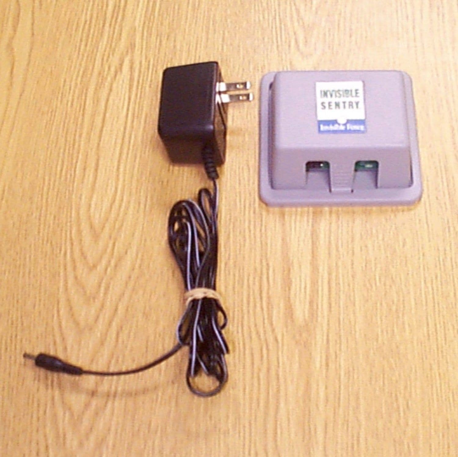
KZ3SENTRY
Aug 08, 2000Invisible Sentry TX: Pet Contaiment Device
Equipment Class
DXX - Part 15 Low Power Communication Device TransmitterKZ3IFA12
Jan 13, 1997Pet Containment Transmitter
Equipment Class
DCD - Part 15 Low Power Transmitter Below 1705 kHzKZ3ICT250
Apr 11, 1996Pet Containment System Transmitter
Equipment Class
DCD - Part 15 Low Power Transmitter Below 1705 kHz