KZ3-050808Safe Dog Monitor/ Dialer Transceiver System
Radio Systems Corporation
Click to zoom
Application Details
- Equipment Class
- DXT - Part 15 Low Power Transceiver, Rx Verified
- Date of Grant
- Apr 25, 2007
- Application Purpose
- Original Equipment
- Date of Application
- Apr 25, 2007
- Equipment Note
- Safe Dog Monitor/ Dialer Transceiver System
- Frequency Range
- 905.00000000 - 924.00000000
- Company
- Radio Systems Corporation
- Country
- United States
Documents & Files
Document Text
Text extracted from the exhibit documents filed with the FCC. Open a document above to read the original.
Users Manual
Rev. 1.0 JAB Safe Dog ® Monitor Installation and Training Manual - DRAFT - Rev. 1.0 JAB 2 G:\PCTEST LAB\2006 Reports\TRP\Safe Dog Monitor - Part 68\TCB Documents\KZ3-050808 manual.doc Need Part Number Table of Contents 1.0 Product Introduction 1.1 Safe Dog ® Monitor System Overview 1.2 Important Precautions and Warning 1.3 Required System Components for Installation 1.4 Product Specifications 1.5 Loop Sensor User Control 1.6 Dialer Unit User Control 2.0 Planning the Safe Dog ® Monitor Installation 2.1 Safe Dog ® Monitor Loop Sensor 2.2 Safe Dog ® Monitor Dialer Unit 3.0 Safe Dog ® Monitor Installation Process 3.1 Programming the Safe Dog ® Monitor Loop Sensor and Dialer Unit 3.1.1 Programming/Synchronization Procedure 3.2 Safe Dog ® Monitor Loop Sensor 3.2.1 Installation Diagram 3.2.2 Mounting the Safe Dog ® Monitor Loop Sensor 3.2.3 Routing the Signal Field Wires 3.2.4 Connecting AC Power 3.2.5 Connecting to the Transmitter Battery Back-up 3.2.6 Calibrating the Signal Field to the Loop Sensor 3.3 Safe Dog ® Monitor Dialer Unit 3.3.1 Installation Diagram 3.3.2 Connecting Power 3.3.3 Connecting the Phone Line 3.3.4 Successful RF Communication Link 3.3.5 Mounting the Safe Dog ® Monitor Dialer Unit 3.3.6 Using Battery Back-up 4.0 Normal Operating Mode – Failure Detection 4.1 Dialer Unit and Loop Sensor Communication 4.2 Alert Conditions 4.2.1 Decrease or Absence of Signal Field 4.2.2 Increase in Signal Field 4.2.3 Loss of RF Link with the Loop Sensor 4.3 Alert Notification 4.3.1 Alert Notification Email 4.3.2 Example of Alert Notification Email 4.3.3 Alert Notification Schedule 4.4 LED Status Indicator Lights 5.0 Safe Dog Monitor Registration - DRAFT - Rev. 1.0 JAB 3 G:\PCTEST LAB\2006 Reports\TRP\Safe Dog Monitor - Part 68\TCB Documents\KZ3-050808 manual.doc Need Part Number 5.1 Registration Process 5.1.1 Pre-registration 5.1.2 Registration – Before Installation 5.1.3 Registration – After Installation - DRAFT - Rev. 1.0 JAB 4 G:\PCTEST LAB\2006 Reports\TRP\Safe Dog Monitor - Part 68\TCB Documents\KZ3-050808 manual.doc Need Part Number 1.0 Product Introduction This document contains important information regarding the installation and operation of the Invisible Fence ® Brand Safe Dog ® Monitor. Prior installation of both the signal field wire and Invisible Fence Brand transmitter is assumed. Review all instructions before installation and use. 1.1 Safe Dog Monitor System Overview The Safe Dog Monitor is designed to continuously monitor the signal transmission of an Invisible Fence Brand transmitter and detect when a change occurs in signal amplitude – specifically, the detection of a wire break condition. The Safe Dog Monitor will also detect an increase or decrease in the signal amplitude and an RF Link Communication failure between the Loop Sensor and Dialer Unit. The Safe Dog Monitor is capable of monitoring the signal of the following Invisible Fence Brand transmitters: r ICT 700 Series Transmitters (700, 725, 750, 775) r ICT 800 Series Transmitters (801, 802, 810) r Invisible Gate ® r Invisible Mask ® II Before the Safe Dog Monitor is installed, the Invisible Fence Brand pet containment system should be completely installed and operational. 1.2 Important Precautions and Warnings Caution: Never install or service any Invisible Fence Brand equipment during a thunderstorm or electrical storm, or when thunder or lightning are in your area. 1.3 Required System Components for Installation The following system components are required for installation of the Safe Dog Monitor. 1. Safe Dog Monitor Loop Sensor [Picture of Loop Sensor] 2. Safe Dog Monitor Dialer Unit [Picture of Dialer Unit] 3. Invisible Fence Brand 700 or 800 Series Transmitter, Invisible Gate, or Invisible Mask II [Picture of 725 and 801 transmitters] 4. Lightning Protection Device (for the Transmitters) – LP 4100/4200 or Max-Dog [Picture of 4100 and Max Dog] 5. AC Adapter – For transmitter and Loop Sensor power supply [Picture of AC adapter] 6. Y-adapter for Loop Sensor power [Picture of Y-adapter] 7. DC Adapter for Dialer Unit power supply [Picture of Adapter] 8. Phone cable [Picture of phone cable included in system pack] 9. 9-volt battery to for battery back-up on the Dialer Unit [Picture of 9-volt included in system pack] 10. Optional: 12v Lead acid battery-back-up for transmitter and Loop Sensor 11. Optional: Y-adapter for connecting Loop Sensor (Included in system pack, show picture) 1.4 Product Specifications – Overview The Safe Dog Monitor consists of two main components: the Loop Sensor and the Dialer Unit. The Loop Sensor is located in close proximity to the Invisible Fence Brand transmitter. The Dialer Unit must be located near a working phone connection. The Dialer Unit communicates with the Loop - DRAFT - Rev. 1.0 JAB 5 G:\PCTEST LAB\2006 Reports\TRP\Safe Dog Monitor - Part 68\TCB Documents\KZ3-050808 manual.doc Need Part Number Sensor via a 900 MHz radio frequency signal. If an alert condition is detected, the Dialer Unit initiates an alert notification to Invisible Fence, Inc. This alert notification is then sent via email to the appropriate Invisible Fence Brand Distributor and Dealer. [Picture of both the Loop Sensor and Dialer Unit] For proper operation, the Loop Sensor and Dialer Unit should never be located more than 250 feet apart (line of sight). The range may vary due to surrounding environmental conditions such as physical obstructions. The Loop Sensor and Dialer Unit also need to be synchronized to each other during installation (See page ___ for further instructions on RF Link Programming). 1.5 Loop Sensor User Controls The Loop Sensor has a push button that is used for linking to the Dialer Unit, calibrating to the set signal field, and re-setting to the default condition. [Show close up picture of Loop Sensor t-board with call-out for the push button] 1. If the Loop Sensor is not linked to the Dialer Unit, and the push button is pressed for less than two seconds, the Loop Sensor will enter the RF Lin…
Text truncated - open the document above for the full version.
External Photos
Monitor/Dialer housing Exterior Photo Rear View Monitor/Dialer housing Exterior Photo Front View Monitor/Dialer housing Exterior Photo Side View Monitor/Dialer housing Exterior Photo bottom View
Internal Photos
Monitor board solder Side View Monitor board component Side View Dialer board solder Side View Dialer board solder Side View Monitor View with cover opened Dialer View with cover opened
Test Report
Reviewed by: FCC ID: KZ3-050808 FCC Pt. 15.249 TEST REPORT (CERTIFICATION) Quality Manager Test Report S/N: Test Dates: EUT Type: 0611130996.KZ3 12/10/2006 - 12/12/2006 Safe Dog Monitor/ Dialer Transceiver System Page 1 of 22 © 2007 PCTEST Engineering Laboratory, Inc. REV 2.3WFC 02/22/07 Applicant Name: Date of Testing: Invisible Fence, Inc. 12/10/2006 - 12/12/2006 1000 Fuller Drive Test Site/Location: Garrett In. 46738-1887 PCTEST Lab, Columbia, MD, USA Test Report Serial No.: 0611130996.KZ3 FCC ID: KZ3-050808 APPLICANT: Invisible Fence, Inc. Model(s): M080801, M080901 EUT Type: Safe Dog Monitor/ Dialer Transceiver System Frequency Range: 905 – 924 MHz FCC & IC Classification: FCC Part 15 Low Power Transceiver, Rx Verified (DXT), Part 68, RSS-210 (Issue 6) FCC Rule Part(s): Part 15.249 Test Device Serial No.: N/A This equipment has been shown to be capable of compliance with the applicable technical standards as indicated in the measurement report and was tested in accordance with the measurement procedures specified in ANSI C-63.4-2003 and RSS. I attest to the accuracy of data. All measurements reported herein were performed by me or were made under my supervision and are correct to the best of my knowledge and belief. I assume full responsibility for the completeness of these measurements and vouch for the qualifications of all persons taking them. PCTEST certifies that no party to this application has been denied the FCC benefits pursuant to Section 5301 of the Anti-Drug Abuse Act of 1988, 21 U.S.C. 862. PCTEST ENGINEERING LABORATORY, INC. 6660-B Dobbin Road, Columbia, MD 21045 USA Tel. 410.290.6652 / Fax 410.290.6554 http://www.pctestlab.com CERTIFICATE OF COMPLIANCE FCC PART 15.249 Certification Reviewed by: FCC ID: KZ3-050808 FCC Pt. 15.249 TEST REPORT (CERTIFICATION) Quality Manager Test Report S/N: Test Dates: EUT Type: 0611130996.KZ3 12/10/2006 - 12/12/2006 Safe Dog Monitor/ Dialer Transceiver System Page 2 of 22 © 2007 PCTEST Engineering Laboratory, Inc. REV 2.3WFC 02/22/07 TABLE OF CONTENTS FCC PART 15.249 MEASUREMENT REPORT...................................................................................................3 1.0 INTRODUCTION ..................................................................................................................................................... 4 1.1 EVALUATION PROCEDURE ............................................................................................................................................... 4 1.2 SCOPE ................................................................................................................................................................................. 4 1.3 PCTEST TEST LOCATION .................................................................................................................................................. 4 2.0 PRODUCT INFORMATION ..................................................................................................................................... 5 2.1 EQUIPMENT DESCRIPTION ............................................................................................................................................... 5 3.0 DESCRIPTION OF TEST ........................................................................................................................................ 6 3.1 CONDUCTED EMISSIONS .................................................................................................................................................. 6 3.2 RADIATED EMISSIONS ....................................................................................................................................................... 7 4.0 ANTENNA REQUIREMENTS.................................................................................................................................. 8 5.0 TEST EQUIPMENT CALIBRATION DATA .............................................................................................................. 9 6.0 TEST RESULTS .................................................................................................................................................... 10 6.1 RADIATED MEASUREMENTS .......................................................................................................................................... 11 6.2 RADIATED RESTRICTED BAND MEASUREMENTS ....................................................................................................... 15 6.3 LINE CONDUCTED PLOT..........................................................................................................................16 7.0 CONCLUSION ....................................................................................................................................................... 17 EXHIBIT A – LABELING REQUIREMENTS ........................................................................................................................ 18 EXHIBIT B – TEST SETUP PHOTOGRAPHS ..................................................................................................................... 19 EXHIBIT C – EUT INTERNAL PHOTOGRAPHS ................................................................................................................. 20 EXHIBIT D – EUT EXTERNAL PHOTOGRAPHS................................................................................................................ 21 EXHIBIT E – USER’S MANUAL........................................................................................................................................... 22 Reviewed by: FCC ID: KZ3-050808 FCC Pt. 15.249 TEST REPORT (CERTIFICATION) Quality Manager Test Report S/N: Test Dates: EUT Type: 0611130996.KZ3 12/10/2006 - 12/12/2006 Safe Dog Monitor/ Dialer Transceiver System Page 3 of 22 © 2007 PCTEST Engineering Laboratory, Inc. REV 2.3WFC 02/22/07 MEASUREMENT REPORT FCC Part 15.249 § 2.1033 General Information APPLICANT: Invisible Fence,…
Text truncated - open the document above for the full version.
Test Setup Photos
Invisible Fence Inc. FCC ID: KZ3-050808 EUT Photographs © 2007 PCTEST Lab. Safe Dog monitor/Dialer Transceiver System Model: M080801, M080901 Invisible Fence Inc. FCC ID: KZ3-050808 EUT Photographs © 2007 PCTEST Lab. Safe Dog monitor/Dialer Transceiver System Model: M080801, M080901 Invisible Fence Inc. FCC ID: KZ3-050808 EUT Photographs © 2007 PCTEST Lab. Safe Dog monitor/Dialer Transceiver System Model: M080801, M080901
Contact Information
Applicant
Clifton P Brick
Technical Contact
PCTEST Engineering Laboratory, Inc.Randy Ortanez
[email protected]410-290-6652
6660-B Dobbin Road · Columbia, Maryland · United States
Test Firm
PCTEST Engineering Laboratory, Inc.Randy Ortanez
Technical Specifications
| # | Rule Parts | Frequency Range | Power Output |
|---|---|---|---|
| 1 | 15C | 905 MHz - 924 MHz | - |
Other Applications from Radio Systems Corporation

KZ3-050259
Nov 08, 2005SHIELDS TRANSMITTER
Equipment Class
DXX - Part 15 Low Power Communication Device Transmitter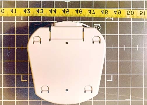
KZ3050241
Mar 28, 2002M024100 Transmitter
Equipment Class
DCD - Part 15 Low Power Transmitter Below 1705 kHz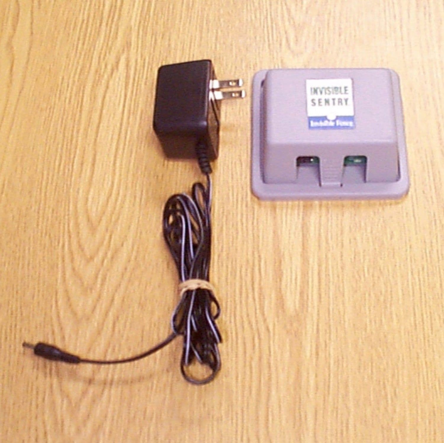
KZ3SENTRY
Aug 08, 2000Invisible Sentry TX: Pet Contaiment Device
Equipment Class
DXX - Part 15 Low Power Communication Device TransmitterKZ3IFA12
Jan 13, 1997Pet Containment Transmitter
Equipment Class
DCD - Part 15 Low Power Transmitter Below 1705 kHzKZ3ICT250
Apr 11, 1996Pet Containment System Transmitter
Equipment Class
DCD - Part 15 Low Power Transmitter Below 1705 kHz