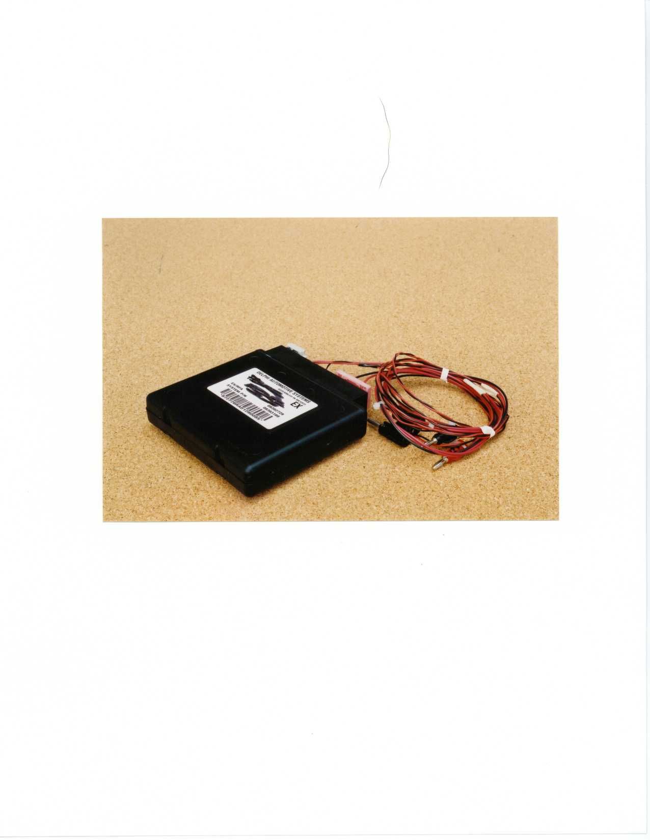
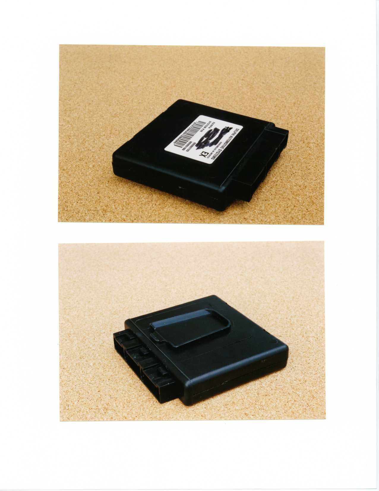
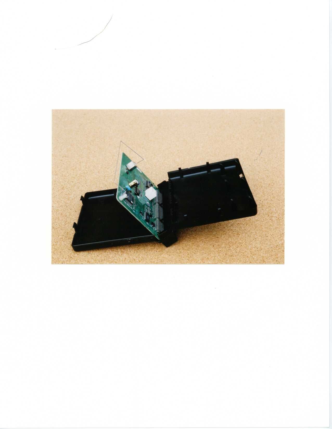
L2C0011RRKE Reciever
APTIV Services US LLC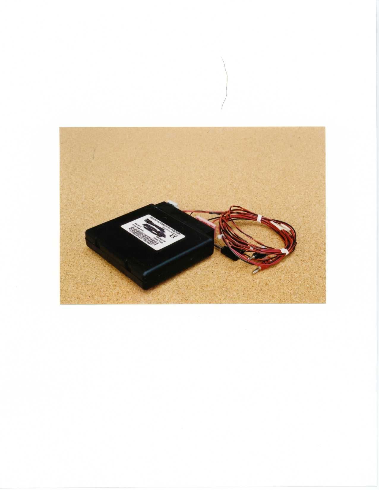
Click to zoom
Application Details
- Equipment Class
- CRR - Superregenerative Receiver
- Date of Grant
- Nov 02, 2000
- Application Purpose
- Original Equipment
- Date of Application
- Oct 05, 2000
- Equipment Note
- RKE Reciever
- Frequency Range
- 433.92000000 - 433.92000000
- Company
- APTIV Services US LLC
- Country
- United States
Documents & Files
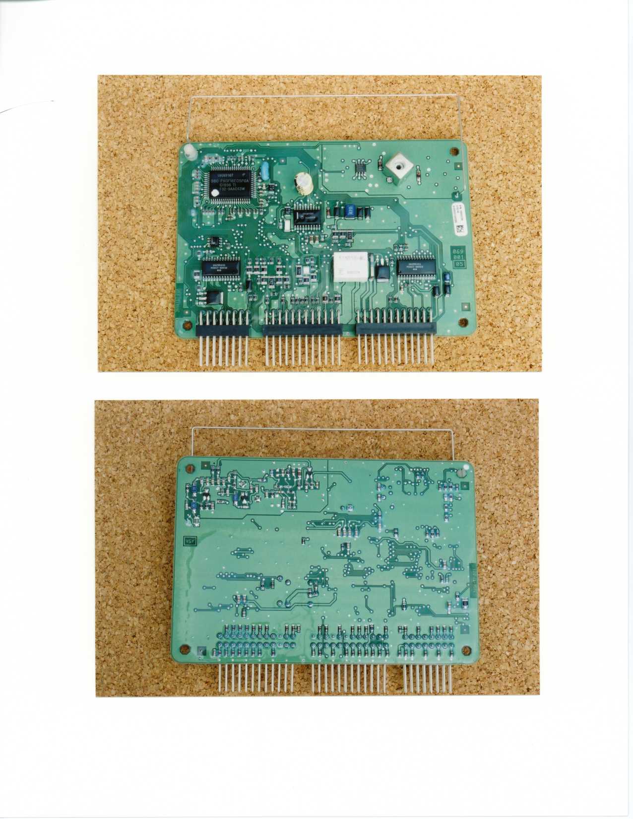
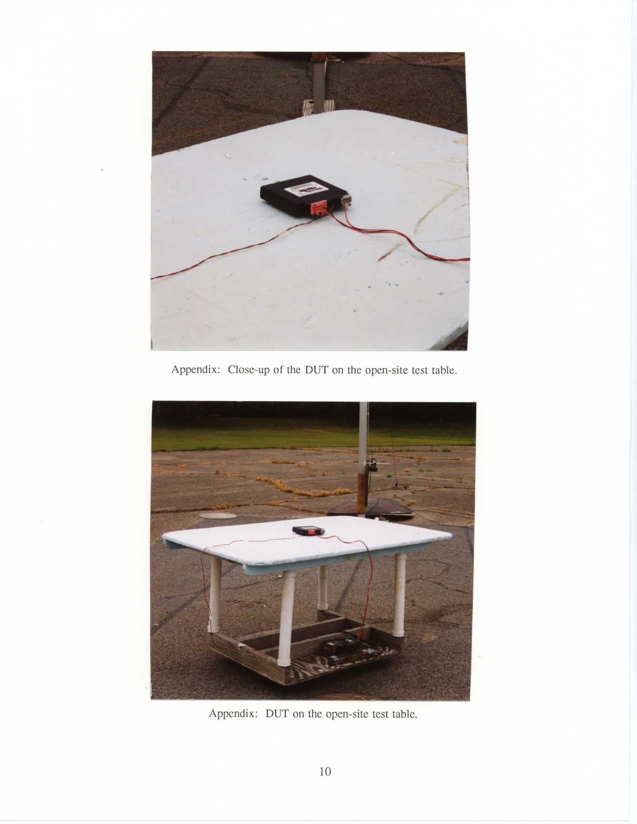
Document Text
Text extracted from the exhibit documents filed with the FCC. Open a document above to read the original.
Block Diagram
Receiver Overview The RF receiver receives and demodulates the incoming 315 Mhz amplitude modulated (AM) RF signals. An internal antenna receives the incoming signals from the transmitter, the signals are amplified through a tuned amplifier, the superregenerative circuit demodulates the 315 Mhz signal and an audio amplifier amplifies the signal which is then sent to the RF microprocessor for data processing (decoding). The receiver has a direct inject sensitivity of approximately 2 uV. Refer to the RF receiver block diagram. The data sent to the RF microprocessor uses a rolling code algorithm for security. RF Front End Amplifier The RF amplifier is mechanized using a transistor in a common emitter configuration with a tuned LC circuit in the collector path to provide selectivity at 315 Mhz. The output of the amplifier is AC coupled to the superregenerative circuit. Superregenerative Circuit The superregenerative circuit is used to demodulate the incoming 315 Mhz signal to a baseband format. The circuit is consists of an RF oscillator operating at 315 Mhz which alternates between an oscillating and non-oscillating condition at a rate known as the quench frequency. When an RF signal (315 Mhz) is applied to the superregenerative circuit, the RF oscillator reaches an oscillating condition faster than when an RF signal is not applied, effectively increasing the quench frequency. The stronger the RF signal, the faster the RF oscillator begins operating. The output of the superregenerative circuit is essentially the variable quench frequency, nominally 600 Khz. The RF oscillator is tuned with a variable inductor which is part of a LC tank circuit. The inductor is adjusted to get maximum sensitivity at 315 Mhz. Nominal bandwidth of the superregenerative circuit id 2.5 Mhz (+/- 3dB). Peak Detect/Low Pass Filter Circuit The output of the superregenerative circuit is sent to the peak detect/low pass filter circuit to demodulate the variable frequency quench oscillation. The output of this circuit is the basedband data (nominally 2 Khz) transmitted by the FOB. Audio Amplifier The low level output of the peak detect/low pass filter circuit is amlified by the audio amplifier comparator circuit. The output of the comparator is sent to the RF uP for signal processing. RF Receiver Block Diagram Front End Amplifier Superregenerative Circuit Peak Detect/Low Pass Filter Circuit Audio Amplifier To RF microprocessor for signal processing
Operational Description
Description of Operation The remote keyless entry system (RKE) is intended for commercial use in various vehicle platforms of General Motors (GM). The remote keyless entry system is comprised of two components. The Body Computer Module (BCM) and a hand-held transmitter (FOB). The RKE system gives the vehicle driver the ability to lock and unlock doors from a distance. The average RF range is 10 meters. RKE System Functionality The RKE system consists of a hand-held fob transmitter used by the vehicle driver and a receiver box located within the vehicle. The transmitter emits RF signals in response to the activation of one or more buttons. Upon activation of a fob button, a message is formed and then transmitted. A message consists of a preamble that indicates the start of a transmission, a unique transmitter ID, a function code and a sophisticated encryption field that prevents recording and subsequent playback of legitimate messages. The receiver periodically checks for the presence of a transmission. When a valid a message is received, the receiver signals the BCM to perform the requested function. The RKE functions are locking/unlocking the car doors, opening the trunk/hatch, and activating the panic alert. The BCM features a super-regenerative AM receiver. The receiver is tuned to a center frequency of 433 MHz. RF messages are received via an internal wire antenna. The software polls for a message every 100ms. If a valid RF message is not received, the receiver goes back to sleep to conserve parasitic current. The super-regenerative receiver is composed of an antenna, RF power switching transistor, front end 433 MHz tuned amplifier, super-regenerative stage, diode detector, backend amplifier, and data slice waveshaper. The backend amplifier and waveshaper are implemented using two halves of a dual LM2904 op amp package. Receiver Overview The RF receiver receives and demodulates the incoming 433 Mhz amplitude modulated (AM) RF signals. An internal antenna receives the incoming signals from the transmitter, the signals are amplified through a tuned amplifier, the superregenerative circuit demodulates the 433 Mhz signal and an audio amplifier amplifies the signal which is then sent to the RF microprocessor for data processing (decoding). The receiver has a direct inject sensitivity of approximately 2 uV. Refer to the RF receiver block diagram. The data sent to the RF microprocessor uses a rolling code algorithm for security. RF Front End Amplifier The RF amplifier is mechanized using a transistor in a common emitter configuration with a tuned LC circuit in the collector path to provide selectivity at 433 Mhz. The output of the amplifier is AC coupled to the superregenerative circuit. Superregenerative Circuit The superregenerative circuit is used to demodulate the incoming 433 Mhz signal to a baseband format. The circuit is consists of an RF oscillator operating at 433 Mhz which alternates between an oscillating and non-oscillating condition at a rate known as the quench frequency. When an RF signal (433 Mhz) is applied to the superregenerative circuit, the RF oscillator reaches an oscillating condition faster than when an RF signal is not applied, effectively increasing the quench frequency. The stronger the RF signal, the faster the RF oscillator begins operating. The output of the superregenerative circuit is essentially the variable quench frequency, nominally 600 Khz. The RF oscillator is tuned with a variable inductor which is part of a LC tank circuit. The inductor is adjusted to get maximum sensitivity at 433 Mhz. Nominal bandwidth of the superregenerative circuit id 2.5 Mhz (+/- 3dB). Peak Detect/Low Pass Filter Circuit The output of the superregenerative circuit is sent to the peak detect/low pass filter circuit to demodulate the variable frequency quench oscillation. The output of this circuit is the basedband data (nominally 2 Khz) transmitted by the FOB. Audio Amplifier The low level output of the peak detect/low pass filter circuit is amlified by the audio amplifier comparator circuit. The output of the comparator is sent to the RF uP for signal processing. RF Receiver Block Diagram Front End Amplifier Superregenerative Circuit Peak Detect/Low Pass Filter Circuit Audio Amplifier To RF microprocessor for signal processing
Contact Information
Applicant
Brian W Johnson(Engineering Group Manager)
Technical Contact
University of Michigan/EECSValdis V Liepa
[email protected]734-483-4211
1301 Beal Ave, · Ann Arbor, Michigan · United States
Non-Technical Contact
University of Michigan/EECSValdis V Liepa
[email protected]734-483-4211
Test Firm
University of MichiganValdis Liepa
Technical Specifications
| # | Rule Parts | Frequency Range | Power Output |
|---|---|---|---|
| 1 | 15B | 433.92 MHz - 433.92 MHz | - |
Other Applications from APTIV Services US LLC
L2CSRR6PS
Apr 09, 2024SRR6PS
Equipment Class
VRD - Part 95 Vehicular Radar SystemsL2C0093TR
Mar 12, 2024Wireless Charging Module
Equipment Class
8CC - Part 18 Consumer Device
L2C0090TR
Oct 04, 2023Passive entry Keyless Go with tire pressure and door handle monitoring radio frequency module
Equipment Class
DCD - Part 15 Low Power Transmitter Below 1705 kHz
L2C0089TR
Jun 05, 2023FO3-TR903BDA
Equipment Class
DSC - Part 15 Security/Remote Control Transmitter
L2C0084TR
Jul 27, 2021Wireless Power Transfer Charger
Equipment Class
8CC - Part 18 Consumer Device