L2C0015TRVehicle Radar Sensor
APTIV Services US LLC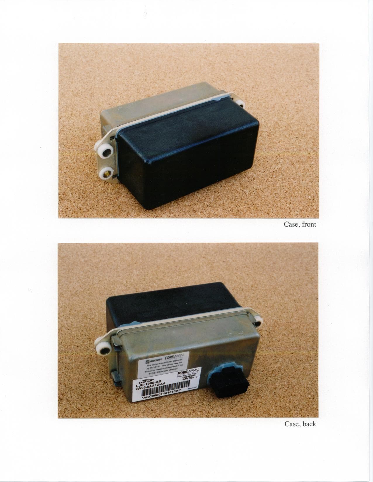
Click to zoom
Application Details
- Equipment Class
- FDS - Part 15 Field Disturbance Sensor
- Date of Grant
- Jul 17, 2001
- Application Purpose
- Original Equipment
- Date of Application
- Apr 26, 2001
- Equipment Note
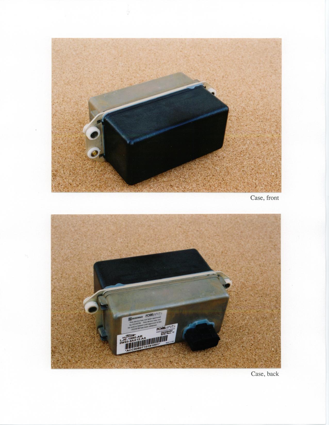
- Vehicle Radar Sensor
- Frequency Range
- 76300.00000000 - 76530.00000000
- Company
- APTIV Services US LLC
- Country
- United States
Documents & Files
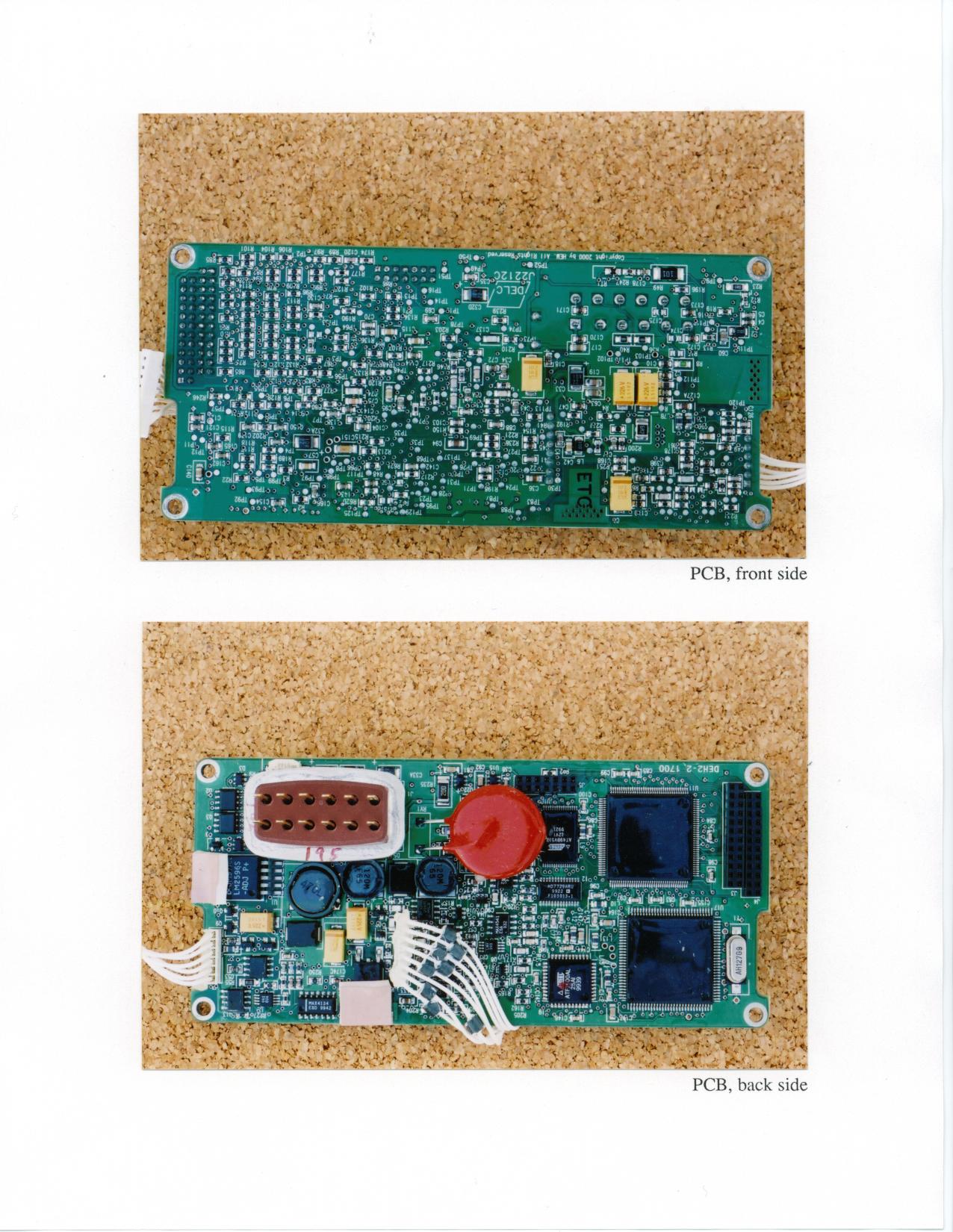
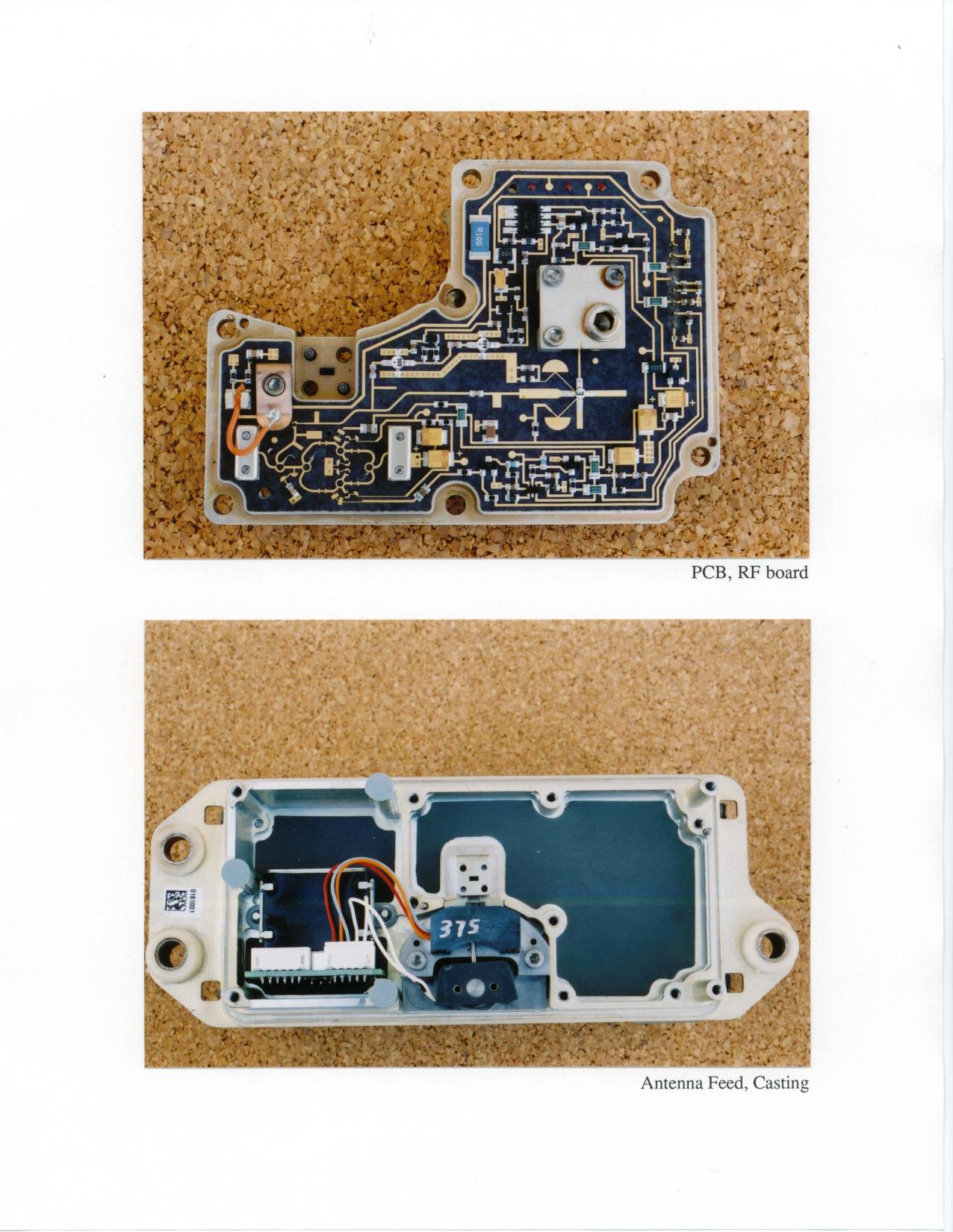
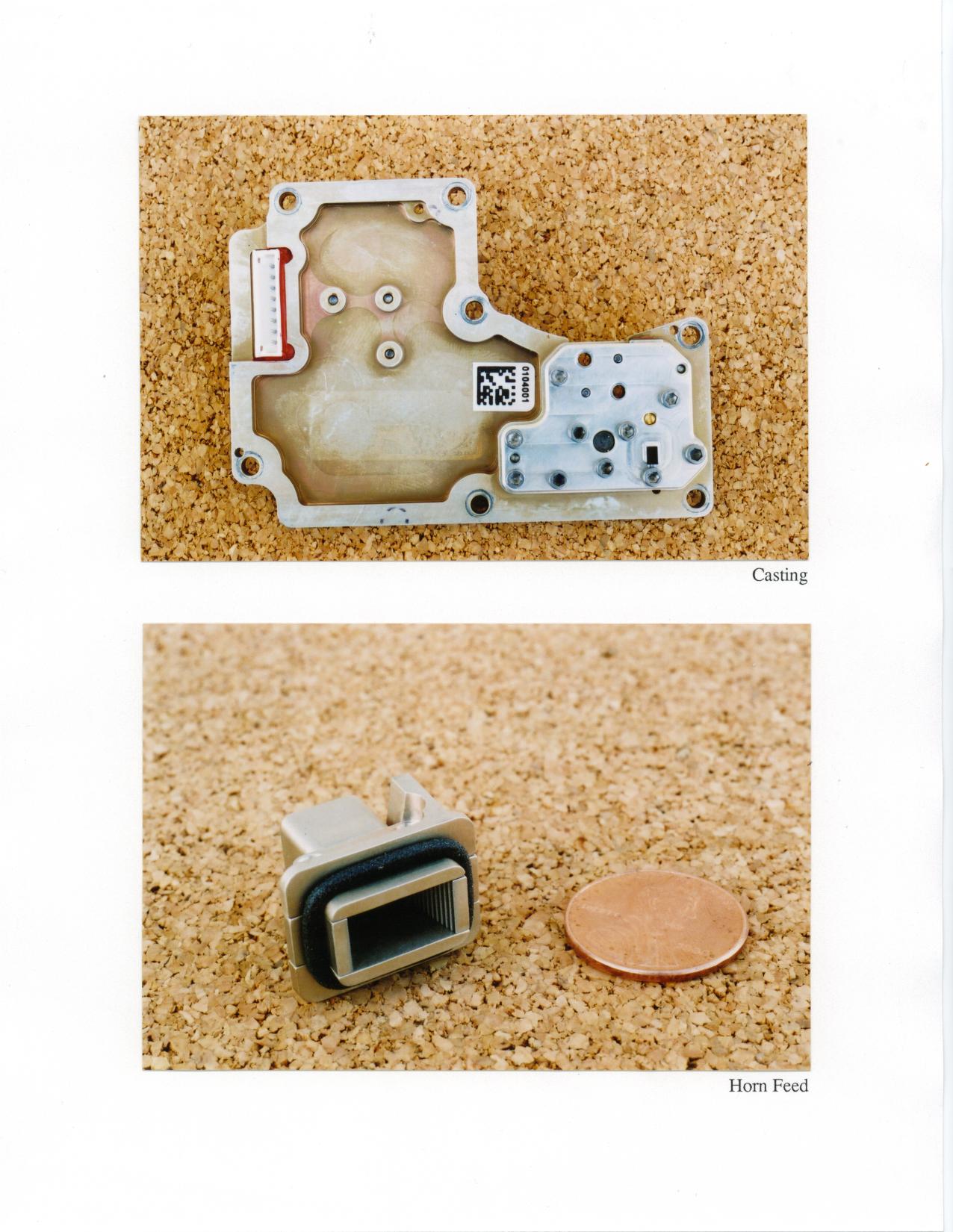
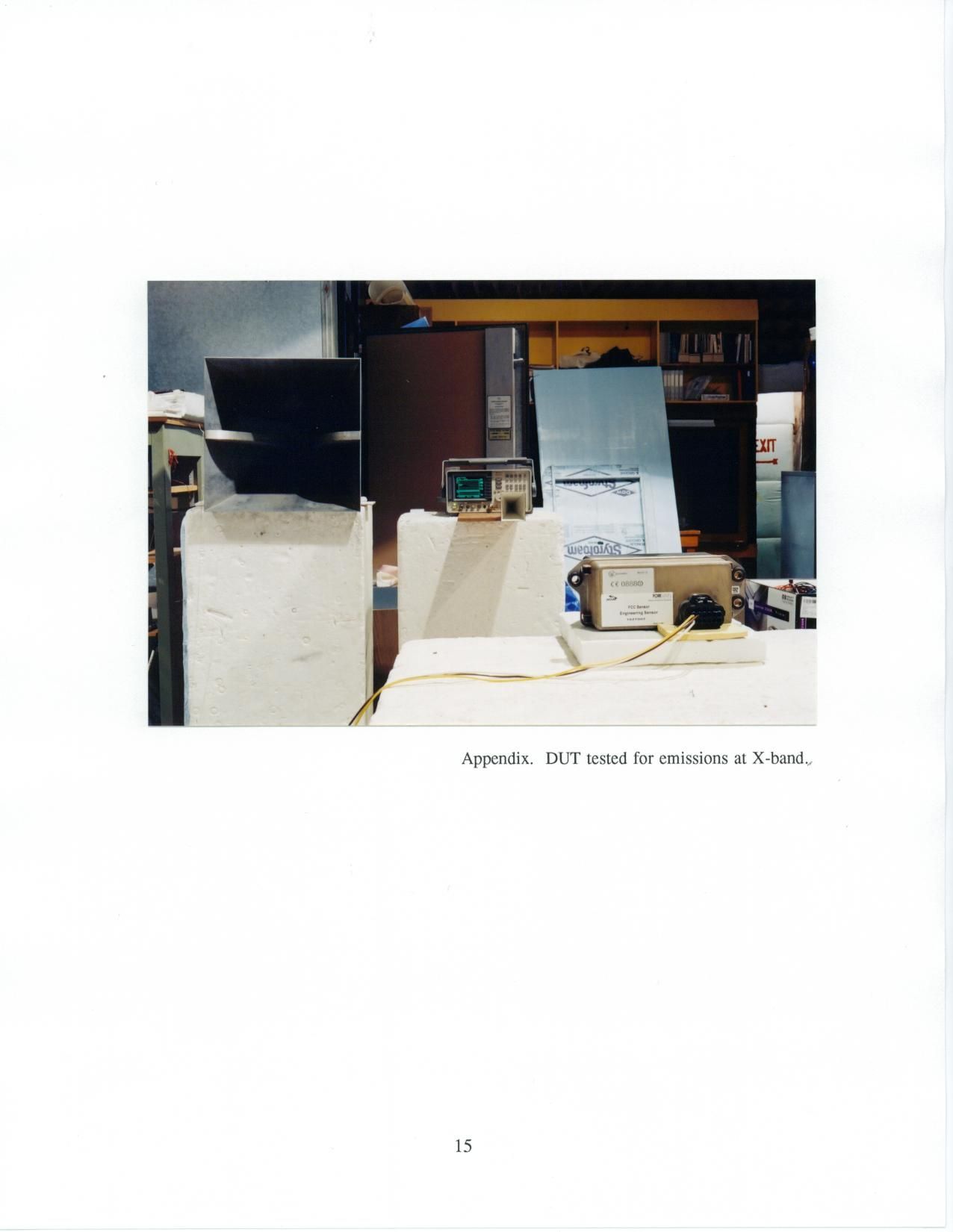
Document Text
Text extracted from the exhibit documents filed with the FCC. Open a document above to read the original.
Users Manual
Re: Certification for Delphi Delco SR Radar PN: 09369080 FCC ID: L2C0015TR CANADA: to be provided by IC USER'S MANUAL INFORMATION (PRELIMINARY) The Vehicle User's Manual is in preparation. The following material will be contained in the manual: FCC ID: L2C0015TR CANADA: to be provided by IC This device complies with Part 15 of the FCC Rules and with RSS-210 of Industry Canada. Operation is subject to the following two conditions: (1) This device may not cause harmful interference, and (2) This device must accept any interference received, including interference that may cause undesired operation. WARNING: Changes or modifications not expressively approved by the party responsible for compliance could void the user's authority to operate the equipment. XK SERIES DRIVERS HANDBOOK SUPPLEMENT JJM 13 02 14/001 2 Adaptive Cruise Control Adaptive Cruise Control (ACC)For your added comfort and convenience this vehicle is fitted with adaptive cruise control. This system maintains a gap from the vehicle ahead or a set road speed if there is no slower vehicle ahead. The system is intended to provide enhanced operation of the vehicle when following other vehicles which are in the same lane and travelling in the same direction. Note: This Supplement superceedes the cruise control operation shown in the Driverís Handbook on pages 3-19 and 3-20. ! WARNING: Adaptive cruise control is not a collision warning or avoidance system. It will not detect:ï stationary or slow moving (below 10km/h) vehicles. ï pedestrians or objects in the roadway. ï oncoming vehicles in the same laneOnly use adaptive cruise control when conditions are favourable, that is, straight, dry, open roads with light traffic.It is the drivers responsibility to stay alert, drive safely and be in control of the vehicle at all times.Keep the front of the vehicle free from dirt, metal badges or objects which may prevent the sensor from operating. The system is operated by an ON/OFF master switch ( A ) mounted in the gear selector surround and six switches mounted on the steering wheel. Brake operation also influences the cruise control system. JWK-171 Adaptive Cruise Control 3 The steering wheel switches operate as follows:( B ) ëSET +í: Set speed or accelerate ( C ) ëñí: Decelerate ( D ) Gap decrease ( E ) ëRESUMEí: Resume set speed ( F ) Gap increase ( G ) ëCANCELí: Cancels without erasing memorised speed Setting a speedPush the ON/OFF switch ( A ) and allow it to come to the raised position. A red warning light on the switch will come on indicating that the system is available for use, unless there is a fault with the system. Accelerate as normal until the required speed is reached. Press the ëSET +í button ( B ) briefly and the vehicle speed will then be stored in the memory and the system engaged. The set speed will be displayed on the message centre.Entering the follow mode ! WARNING: When in follow mode the vehicle will not decelerate automatically to a stop, nor will the vehicle always decelerate quickly enough to avoid a collision without driver intervention.Once a set speed has been selected, the driver can release the accelerator and the set road speed will be maintained.When a vehicle ahead enters the same lane or a slower vehicle is ahead in the same lane, the vehicle speed will be adjusted automatically until the time gap to the vehicle ahead corresponds to the gap allowed by the system. The vehicle is now in ëfollow modeí.The tell tale in the instrument cluster will be illuminatedand the message centre will display the gap for four seconds. JWK-170 SETSPEED ÏÍÌ ̋NPÓK GAP 4 Adaptive Cruise Control The vehicle will then maintain the constant time gap to the vehicle ahead until:ï the vehicle ahead accelerates to a speed above the set speed. ï the vehicle ahead moves out of lane or out of view.ï the vehicle ahead slows so that ëlow speed automatic switch offí occurs. ï a new gap distance is set.If necessary, the vehicle brakes will be automatically applied to slow the vehicle to maintain the gap to the vehicle in front. The maximum braking rate which is applied by the ACC system is limited and can be overridden by the driver intervening and applying the brakes, if required.Note: Driver braking will cancel the adaptive cruise control function.If the ACC uses its maximum braking level then an audible warning will sound while the ACC continues to brake. This is accompanied by a red warning light and ëDRIVER INTERVENEí will be displayed on the message centre. The driver should take IMMEDIATE action.When in follow mode the vehicle will automatically return to the set speed when the road ahead is clear or the vehicle in front is beyond the set gap or changes lane. Low speed automatic switch offIf the speed of the vehicle decreases below 24 km/h, the ACC system will be automatically switched OFF and the tell tale will go out. If the brakes were being applied by the ACC system, they will be slowly released. This will be accompanied by an audible warning, a red warning light and ëDRIVER INTERVENEí will be displayed on the message centre. The driver must take control.Overriding the set speed /follow modeThe set speed and gap can be overridden by pressing the accelerator pedal when cruising at constant speed or follow mode. If the vehicle is in follow mode, the tell tale indicator will go out when the ACC is overridden by the driver using the accelerator and ëCRUISE OVERRIDEí will be displayed on the message centre. When the accelerator is released the ACC function will operate again and vehicle speed will decrease to the set speed, or a lower speed if follow mode is active. ! WARNING: Whenever the driver is overriding the ACC, the ACC automatic braking will not be available to maintain separation from any vehicle ahead. Adaptive Cruise Control 5 Changing the set speedThere are three ways to change the set speed:1. Accelerate or brake to the required speed and press the ëSET +í button ( B ). 2. Increase or decrease the speed by pressing and …
Text truncated - open the document above for the full version.
Attestation Statements
Re: Certification for Delphi Delco SR Radar PN: 09369080 FCC ID: L2C0015TR CANADA: to be provided by IC POWER OF ATTORNEY A letter granting Valdis V. Liepa the Power of Attorney is on file and can be provided when so requested. Re: Certification for Delphi Delco SR Radar PN: 09369080 FCC ID: L2C0015TR CANADA: to be provided by IC GENERAL PRODUCT INFORMATION The device, for which certification is pursued, has been designed by: Delphi-Delco Electronics Systems One Corporate Center Kokomo, IN 46904-9005 Tom Hoover Tel: 765 451 0900 Fax: 765 451 5312 It will be manufactured by: HE Microwave Steve Walland Tel: 520 806 8802 Fax: 520 806 8808 It will be marketed and serviced by: Jaguar Dealers in North America
Block Diagram
ACC2 System Block Diagram Power Ignition Power/Control RF Out RF In Baseband FMCW Transceiver Antenna Actuator RF Beam Motor Position CAN Bus Yaw Rate Sensor Battery Linearizer Radar Control Module (RCM) ACC2 Transceiver Block Diagram Gunn Diode VCO Waveguide Block 3 dB DIVIDER 90 DEG HYBRID 256 12.7 GHz DRO RF BOARD DRO FEEDBACK I-Channel Q-Channel GNDRV RCM Magic Tee Antenna Port Waveguide/μstrip transistions 6 dB Coupler
ID Label/Location Info
D 8 7 6 3 2 9 1 10 10
ID Label/Location Info
.a DWG NO SHT 1004352 OF; REVISION RECORD DATE REV SH.REV’DDESCRIPTIONDR CK 6FEBOl 1PRELIMINARY RELEASESJP CS 6FEBOl AINITIAL RELEASE PER EC0 1004352mlASJP CS ‘6APROl BREVISED PER EC0 1004352AB SJP MW 4 53.1 mm REF- r 7 \ e I rnYKA0001 KC-2 0888 @ CC1 M.L. SH Nr1513/2000] 25.4mm REF FCCID:L2COOETR CANADA: \ I I . MIS PRINT/DOCUMENT IS FOR REFERENCE ONLY UNLESS SIGNED BY AN AUTHORIZED INDMDUAL (REF. ENG ~0~02). AU SIGNED PRINTS/DOCUMENTS MUST BE VERlFlED FOR THE LATEST REVISION BEFORE USE. APPD. FOR USEDATE EMISSIONS LABEL HE MICROWAVE TUCSON, AZ.
ID Label/Location Info
.a DWG NO SHT 1004352 OF; REVISION RECORD DATE REV SH.REV’DDESCRIPTIONDR CK 6FEBOl 1PRELIMINARY RELEASESJP CS 6FEBOl AINITIAL RELEASE PER EC0 1004352mlASJP CS ‘6APROl BREVISED PER EC0 1004352AB SJP MW 4 53.1 mm REF- r 7 \ e I rnYKA0001 KC-2 0888 @ CC1 M.L. SH Nr1513/2000] 25.4mm REF FCC ID:L2COO15TR CANADA: \ I I . MIS PRINT/DOCUMENT IS FOR REFERENCE ONLY UNLESS SIGNED BY AN AUTHORIZED INDMDUAL (REF. ENG ~0~02). AU SIGNED PRINTS/DOCUMENTS MUST BE VERlFlED FOR THE LATEST REVISION BEFORE USE. APPD. FOR USEDATE EMISSIONS LABEL HE MICROWAVE TUCSON, AZ.
Operational Description
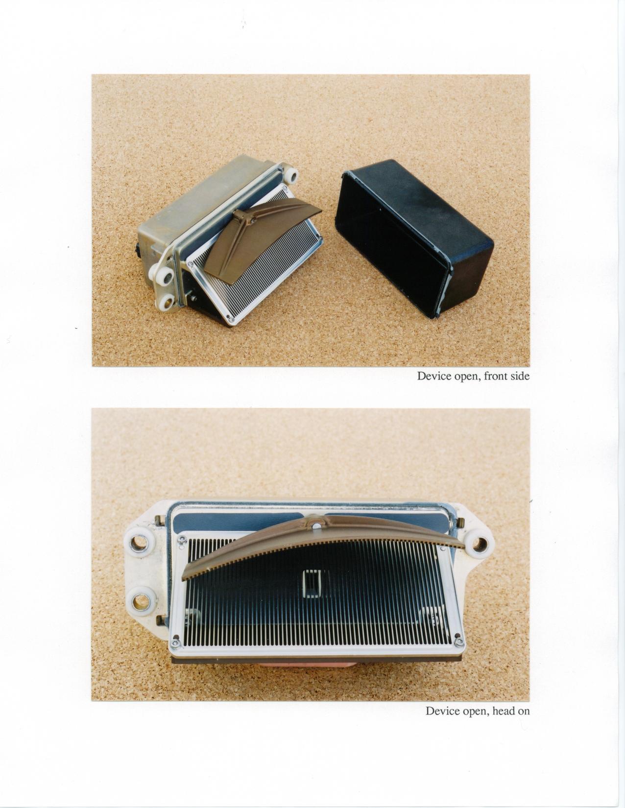
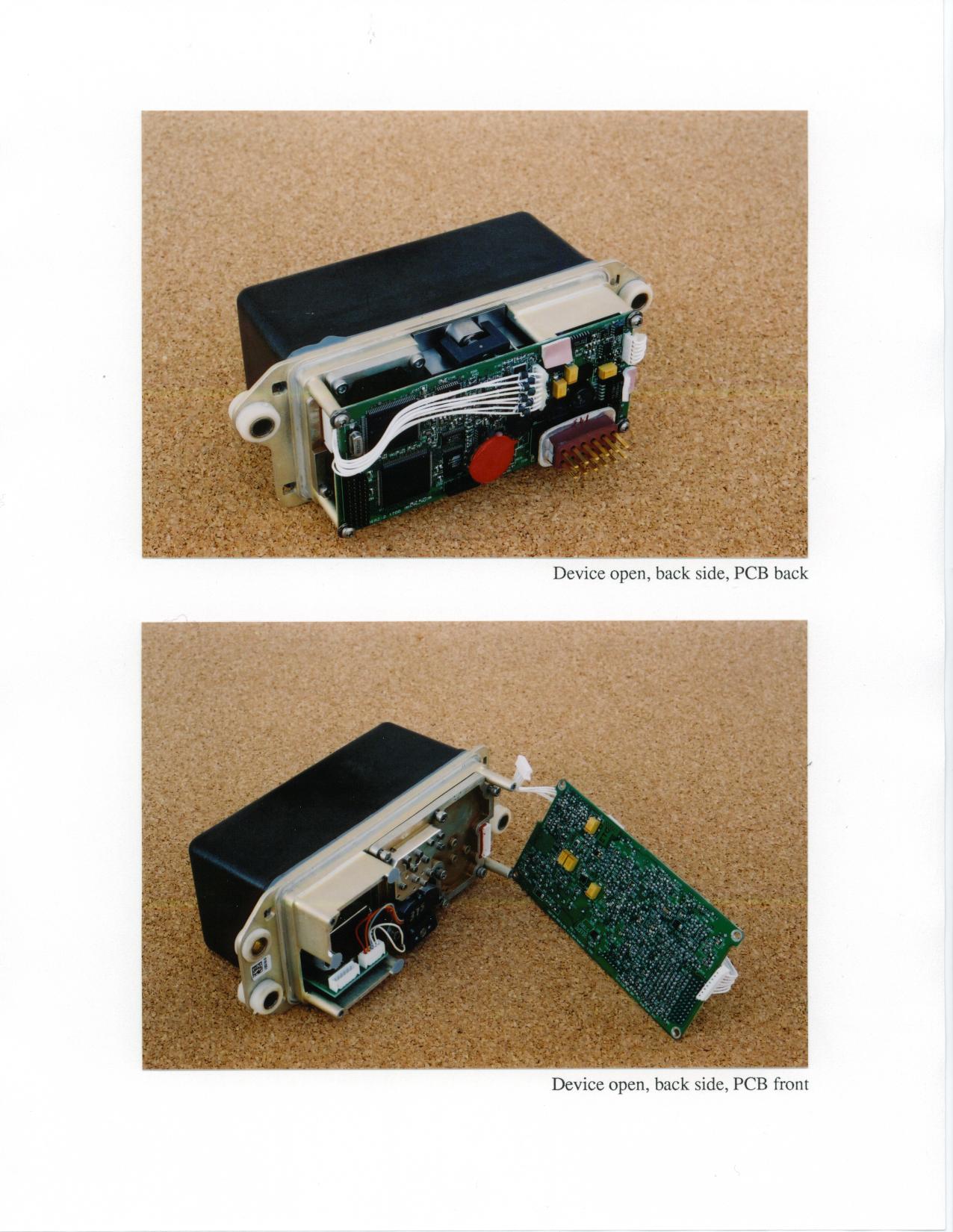
DELPHI DELCO ELECTRONICS PROPRIETARY DELPHI DELCO ELECTRONICS PROPRIETARY PLOT H E MICROWAVE PROPRIETARY 05/11/001003905 REV APage 2 of 15 DELPHI DELCO ELECTRONICS PROPRIETARY 2 ACC2 SENSOR PRODUCT DEFINITION DOCUMENT for JAGUAR MY2001 ACC2 ADAPTIVE CRUISE CONTROL SYSTEM Document No. HEM 1003905 9 January 2000 Delphi Delco Electronics HE Microwave 05/11/001003905 REV APage 5 of 15 DELPHI DELCO ELECTRONICS PROPRIETARY 5 1.0 INTRODUCTION 1.1 Background and Intent The 2001 MY Jaguar ACC2 Adaptive Cruise Control (ACC) System consists of a Mech scanned antenna, actuator, millimeter wave (MMW) transceiver, radar control module (RCM) and angular rate sensor. This document provides the functional and performance requirements for the Sensor component of the ACC2 System. The ACC2 System automatically adjusts host vehicle speed (via throttle and limited braking) to maintain a selected following interval to the closest moving vehicle within the projected path of the ACC vehicle. In special situations, the ACC2 system also invokes limited braking in response to stopped objects in the path of the host vehicle. The ACC function is intended for both straight and curved roadways in clear and adverse weather conditions. The ACC2 Sensor is required to output track files on moving and stationary objects in the forward area. Discrimination capability is needed to track closely spaced vehicles and to distinguish valid vehicle targets from roadside clutter and other stationary objects. Algorithms which execute within a micro-controller on board the RCM calculates vehicle path, selects the closest in-path vehicle from the sensor track file data, determines throttle and brake commands, and interfaces with the vehicle bus. In general, stationary objects and vehicles shall be rejected except that decelerating vehicles must be reported to a complete stop. 1.2 Sensor Functions The primary Sensor functions are detection, parameter estimation, tracking and diagnostics. The Sensor scans a narrow beam to detect all targets within its specified field of view (FOV). A wide azimuth FOV is implemented to support ACC on curved roadways with overscan to accommodate misalignment. For each detection, the Sensor estimates target range, range rate, acceleration, and angle parameters. These parameters are input to the tracking function which maintains track files on all targets within the FOV. Host vehicle yaw rate and speed is processed by the Sensor in the parameter estimation and tracking functions. Host vehicle speed is used to identify moving and stationary targets. Yaw rate (and speed) are used to estimate and smooth target offset from lane center. 05/11/001003905 REV APage 6 of 15 DELPHI DELCO ELECTRONICS PROPRIETARY 6 1.3 Radar System Overview The Sensor is a millimeter wave (MMW) frequency modulated continuous wave (FMCW) radar operating at 76.5 GHz frequency (midband). The radar system consists of a transmit/receive antenna, antenna actuator assembly, transceiver assembly, and Radar Control Module (RCM), as shown in Figure 1.3-1. The antenna provides a narrow pencil beam which is mechanically scanned to cover the required azimuth region. The transceiver generates the FMCW transmit waveform and, on receive, performs direct conversion to baseband (I and Q). A multiple slope FM waveform is used to determine unambiguous target range and range rate data. Baseband data from the transceiver is analog filtered and then digitized by the RCM which performs the radar signal and data processing functions from detection through target tracking. In addition, the RCM performs transceiver control and antenna scan control. A closed loop linearizer is implemented to control the frequency modulation of the transceiver. A closed loop controller is used to control antenna scanning based on position feedback from the actuator. Power Ignition Power/Control RF Out RF In Baseband FMCW Transceiver Antenna Actuator RF Beam Motor Position CAN Bus Yaw Rate Sensor Battery Linearizer Radar Control Module (RCM) Figure 1.3-1 Sensor Block Diagram
Contact Information
Applicant
Brian W Johnson(Engineering Group Manager)
Technical Contact
University Of Michigan / EECSValdis V Liepa
[email protected]734-483-4211
1301 Beal Ave. · Ann Arbor, Michigan · United States
Non-Technical Contact
University of Michigan / EECSValdis V Liepa
[email protected]734-483-4211
Test Firm
University of MichiganValdis Liepa
Technical Specifications
| # | Rule Parts | Frequency Range | Power Output |
|---|---|---|---|
| 1 | 15C | 76.30 GHz - 76.53 GHz | - |
Other Applications from APTIV Services US LLC
L2CSRR6PS
Apr 09, 2024SRR6PS
Equipment Class
VRD - Part 95 Vehicular Radar SystemsL2C0093TR
Mar 12, 2024Wireless Charging Module
Equipment Class
8CC - Part 18 Consumer Device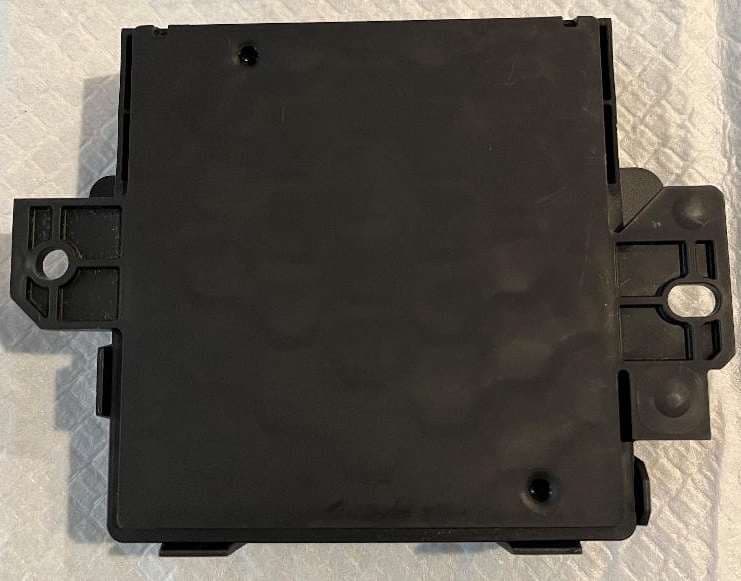
L2C0090TR
Oct 04, 2023Passive entry Keyless Go with tire pressure and door handle monitoring radio frequency module
Equipment Class
DCD - Part 15 Low Power Transmitter Below 1705 kHz
L2C0089TR
Jun 05, 2023FO3-TR903BDA
Equipment Class
DSC - Part 15 Security/Remote Control Transmitter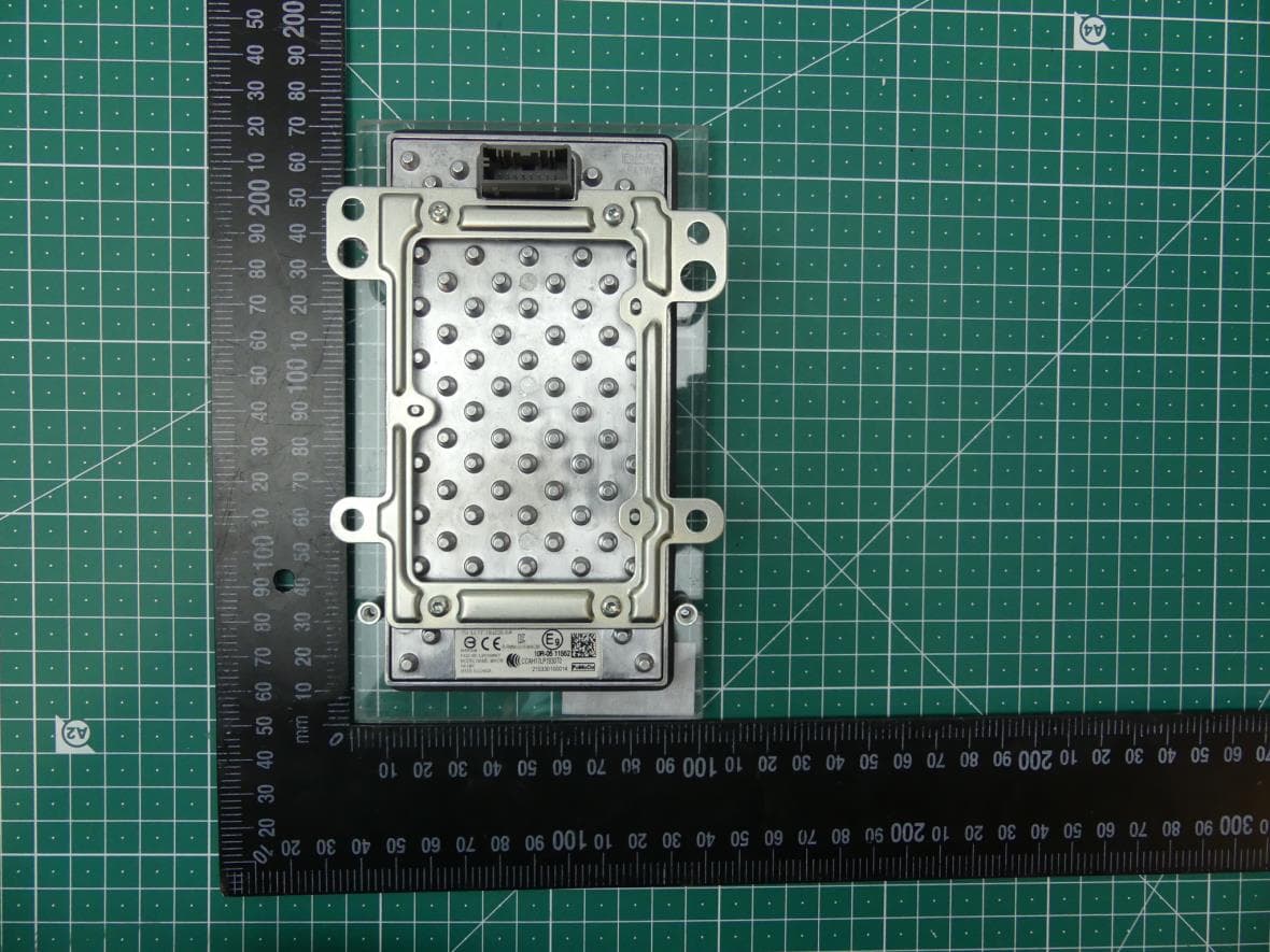
L2C0084TR
Jul 27, 2021Wireless Power Transfer Charger
Equipment Class
8CC - Part 18 Consumer Device