L2C0019RAutomotive RX
APTIV Services US LLC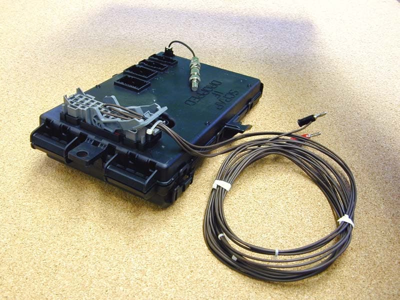
Click to zoom
Application Details
- Equipment Class
- CYY - Communications Receiver used w/Pt 15 Transmitter
- Date of Grant
- Dec 26, 2002
- Application Purpose
- Original Equipment
- Date of Application
- Dec 26, 2002
- Equipment Note
- Automotive RX
- Frequency Range
- 315.00000000 - 315.00000000
- Company
- APTIV Services US LLC
- Country
- United States
Documents & Files
Document Text
Text extracted from the exhibit documents filed with the FCC. Open a document above to read the original.
Users Manual
Re: Certification for Delphi-Delco SJB Receiver Model: SJB FCC ID: L2C0019R IC: 3432A-0019R USER'S MANUAL INFORMATION (PRELIMINARY) The User's Manual is in preparation. The following material will be contained in the manual: FCC ID: L2C0019R IC: 3432A-0019R This device complies with Part 15 of the FCC Rules and with RSS-210 of Industry Canada. Operation is subject to the following two conditions: (1) This device may not cause harmful interference, and (2) This device must accept any interference received, including interference that may cause undesired operation. WARNING: Changes or modifications not expressively approved by the party responsible for compliance could void the user's authority to operate the equipment. The term “IC:” before the radio certification number only signifies that Industry Canada technical specifications were met.
Block Diagram
RF RECEIVER BLOCK DIAGRAM VCCCD RF-ON_D RD_DATA_IN EXT_ANTENNA_IN EXT_ANTENNA_GND 315 MHz RKE RECEIVER The RX contains the following Oscillators: Digital: 5.08906MHZ, 8.0MHZ RF: 10.178125MHZ
Cover Letter(s)
Re: Certification for Delphi-Delco SJB Receiver Model: SJB FCC ID: L2C0019R IC: 3432A-0019R POWER OF ATTORNEY A letter granting Valdis V. Liepa the Power of Attorney is on file and can be provided when so requested. Re: Certification for Delphi-Delco SJB Receiver Model: SJB FCC ID: L2C0019R IC: 3432A-0019R REQUEST FOR CONFIDENTIALITY Pursuant to 47 CRF 0.459, Delphi-Delco requests that a part of the subject application be held confidential. This comprises Exhibits (5) Schematics (10) Parts List (Part of Exhibit only) Delphi-Delco has spent substantial effort in developing this product and it is one of the first of its kind in industry. Having the subject information easily available to "competition" would negate the advantage they have achieved by developing this product. Not protecting the details of the design will result in financial hardship. If there are any questions regarding this request, please contact me at the above address or call 734-483-4211, fax 734-647-2106 or e-mail [email protected]. Sincerely, Valdis V. Liepa Research Scientist University of Michigan December 20, 2002 Re: Certification for Delphi-Delco SJB Receiver Model: SJB FCC ID: L2C0019R IC: 3432A-0019R STATEMENT OF MODIFICATIONS There were no modifications made to the DUT by this test laboratory. (Also see Section 3.1 of the attached Test Report). _____________________ Valdis V. Liepa Research Scientist Re: Certification for Delphi-Delco SJB Receiver Model: SJB FCC ID: L2C0019R IC: 3432A-0019R GENERAL PRODUCT INFORMATION The device, for which certification is pursued, has been designed by: Delphi-Delco Electronics Systems 3432A-0019R One Corporate Center Kokomo, IN 46904-9005 Brian W Johnson, Team Leader, MS# CT-200A Tel: 765-451-5770 Fax: 765-451-0174 It will be manufactured by: Delphi Automotive Systems - Reynosa Parque Industrial Reynosa Tamaulipas, Mexico Brian W Johnson, Team Leader, MS# CT-200A Tel: 765-451-5770 Fax: 765-451-0174
ID Label/Location Info
FCC ID: L2C0019R IC: 3432A-0019R
Operational Description
Smart Junction Box (SJB) The purpose of the RF receiver (together with a RF transmitter) is to provide the customer with a wireless link that with let the customer to control some basic functions inside of the car, like the unlock – lock doors, alarms and panic. This RF receiver is intended to work for short range operation (30 meters). The RF receiver main function is to receive the RF signal and recover the modulating signal (data information), then it will transfer the information to a main microcontroller which will process that information. RF Receiver Technical Description: Below you can see a block diagram of the RF receiver, it consists of two LNA sections to provide well RF amplification (one internal, and other external), all the RF signal processs is handle internally in the chip, this chip is single chip ASK Superheterodyne Receiver (SHR) for the frequency bands 315 and 345MHz. The device contains a low noise amplifier (LNA), a double balanced mixer, a fully integrated VCO, a PLL synthesiser, a crystal oscillator, a limiter with RSSI generator, a data filter, a data comparator (slicer) and a peak detector. The LNA is a cascade amplifier with a voltage gain of 15 to 20dBm per stage. The gain figure is determined by the external matching networks situated ahead of LNA and between the LNA output LNO (Pin 6) and the Mixer Inputs MI and MIX (Pins 8 and 9), after the amplification a double balanced Mixer down converts the input frequency (RF) in the range of 310 or 345MHz to the intermediate frequency (IF) at 10.7MHz with a voltage gain of approximately 21dB. A low pass filter with a corner frequency of 20MHz is built on chip in order to suppress RF signals to appear at the IF output ( IFO pin). The IF output is internally consisting of an emitter follower that has a source impedance of approximately 330 ?= to facilitate interfacing the pin directly to a standard 10.7MHz ceramic filter without additional matching cir- cuitry. Finally the 10.7 MHz signal is passed trough a RSSI amplifier (signal strength detector), the output of this amplifier is the modulating signal (data recovered), finally the data output is cleaned by a stage of low frequency filter, data then is transfer to main microcontroller (which is not part of the RF receiver) For signal processing.
Contact Information
Applicant
Brian W Johnson(Engineering Group Manager)
Technical Contact
University of Michigan/EECSValdis V Liepa
[email protected]734-483-4211
1301 Beal Ave. · Ann Arbor, Michigan · United States
Non-Technical Contact
University of Michigan/EECSValdis V Liepa
[email protected]734-483-4211
Test Firm
University of MichiganValdis Liepa
Technical Specifications
| # | Rule Parts | Frequency Range | Power Output |
|---|---|---|---|
| 1 | 15B | 315 MHz - 315 MHz | - |
Other Applications from APTIV Services US LLC
L2CSRR6PS
Apr 09, 2024SRR6PS
Equipment Class
VRD - Part 95 Vehicular Radar SystemsL2C0093TR
Mar 12, 2024Wireless Charging Module
Equipment Class
8CC - Part 18 Consumer Device
L2C0090TR
Oct 04, 2023Passive entry Keyless Go with tire pressure and door handle monitoring radio frequency module
Equipment Class
DCD - Part 15 Low Power Transmitter Below 1705 kHz
L2C0089TR
Jun 05, 2023FO3-TR903BDA
Equipment Class
DSC - Part 15 Security/Remote Control Transmitter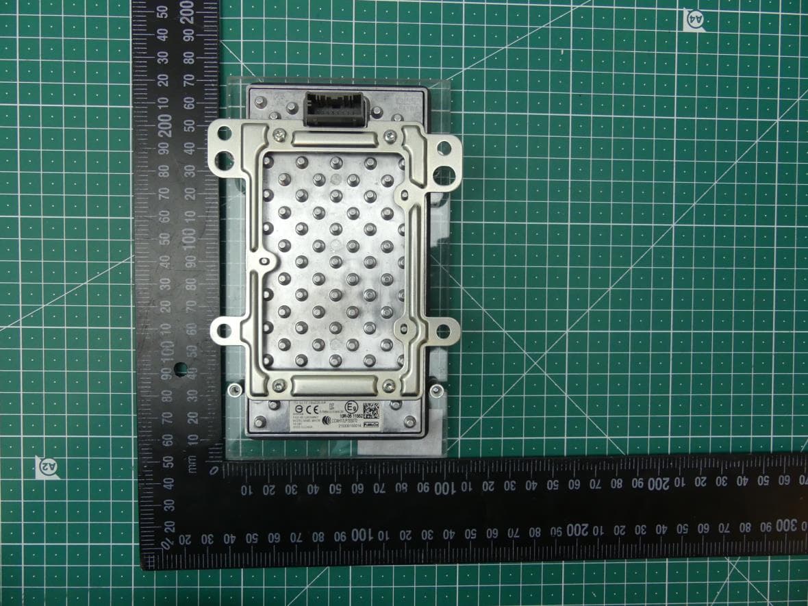
L2C0084TR
Jul 27, 2021Wireless Power Transfer Charger
Equipment Class
8CC - Part 18 Consumer Device