L2C0023TRUWB Vehicular Radar
APTIV Services US LLCApplication Details
- Equipment Class
- UWB - Ultra Wideband Transmitter
- Date of Grant
- Mar 28, 2005
- Application Purpose
- Original Equipment
- Date of Application
- Oct 15, 2004
- Equipment Note
- UWB Vehicular Radar
- Frequency Range
- 23967.00000000 - 24977.00000000
- Company
- APTIV Services US LLC
- Country
- United States
Documents & Files
Document Text
Text extracted from the exhibit documents filed with the FCC. Open a document above to read the original.
Users Manual
Re: Certification for Delphi Delco UWB Radar Model: 12237659 FCC ID: L2C0023TR IC: 3432A-0023TR USER'S MANUAL INFORMATION (PRELIMINARY) The User's Manual is in preparation. The following material will be contained in the manual: FCC ID: L2C0023TR IC: 3432A-0023TR This device complies with Part 15 of the FCC Rules and with RSS-210 of Industry Canada. Operation is subject to the following two conditions: (1) This device may not cause harmful interference, and (2) This device must accept any interference received, including interference that may cause undesired operation. WARNING: Changes or modifications not expressively approved by the party responsible for compliance could void the user's authority to operate the equipment. The term “IC:” before the radio certification number only signifies that Industry Canada technical specifications were met.
Attestation Statements
December 22, 2004 Re: FCC ID L2C0023TR Applicant: Delphi Delco Electronics Systems Correspondence Reference Number: 28186 731 Confirmation Number: EA384397 The following is in response to the questions raised in certification of the above application. 1) A sealed enclosure is insufficient justification for Confidentiality of the internal photos. If someone can still open the device, and take photos then the internal photos cannot be held confidential. Provide sufficient justification or submit a new confidential letter without the internal photos listed. Delphi has decided that, since a sealed enclosure has been deemed insufficient justification for Confidentiality, they will remove their request to attain permanent internal photo confidentiality. However, Delphi does request short term confidentiality for the internal photos exhibit. This request is justified, as the device in question is scheduled for release in the 2006 automotive model year. Thus, these devices will not be available to the general public for 8 months. A set of updated cover letters has been uploaded with this response. 2) For UWB devices, a 20 dB/decade is used. Do not use a 40 dB/decade extrapolation factor. Please submit a corrected test report. Please note that use of 20 dB/dec in the near-field of the device conflicts with the FCC’s microwave measurement procedures document (FCC 20040514-002). Has the FCC decided to modify the microwave measurements procedures? If not, please justify why microwave measurement procedures do not apply to UWB devices operating in the microwave region, as the rate of field decay from such devices does not deviate from those of other microwave devices certified under other sections of the FCC regulations. Please also see our response to question 5) below. 3) Justify a clear demonstration of classification of the 8 GHz and 16 GHz emission as digital circuitry per 15.521(c). The 16 GHz emission is an LO generated for use only in the receive chain of the radar (see block diagram), and as part of a receiver > 960 MHz should not subject per FCC 15.101(b). The 8 GHz radiated emission is not an emission from the TX chain, but is believed to be a spurious emission emanating from the device receive chain LO (the doubler in the RX chain requires the largest portion of the LO power, the reference signal to the transmitter is 14 dB lower). The 8 GHz emission does not radiate at a level above the UWB emission from the transmitter’s antenna, as computed from the theoretical performance of the BPSK digital encoder and both the calculated and measured response of the TX chain Bandpass Filter (-30 dB at 8 GHz). The waveform associated with the particular PN code has the center spectral line reduced by 36 dB relative to the first upper and lower spectral lines of the waveform. Thus, this emission is believed to be solely an emission from the receiver portion of the radar. Thus, as a component of a receiver > 960 MHz, this emission should not subject per FCC 15.101(b). In the test report, these emissions were “labeled” as digital emissions when demonstrating that they meet the FCC Class B limit. The test report has been revised and uploaded. 4) Provide a description of the measurement procedure used for measuring compliance with Section 15.515(c). Initially, the peak level of the radiated emissions is measured over all azimuth and elevation angles. (The dominant source of radiated energy is the transmit antenna.) This peak occurs at the same angle that the antenna gain is maximized, which is perpendicular to the radome (azimuth = 0 degrees). This is measured with the radar in spread spectrum mode, operating as it would in the field, with the receive antenna co-polarized with the radar antenna. Next, the radar module is placed in a CW test mode, with the spread spectrum modulation disabled. In this mode, the unit transmits higher power spectral density, providing a means of making the pattern measurement with sufficient dynamic range. With the device in this mode, the worst case azimuth and elevation patterns are measured. Once antenna patterns are obtained, the peak UWB transmitted power level, measured at 24.0 GHz in Section 6.2, is assumed to correlate to the peak of the measured pattern. The off angle power is then computed by subtracting the sidelobe level (dBc) from the main lobe transmitted power. 5) In table 6.1, measurement distances at the upper frequencies are at 0.3, 0.1 and 0.05 meters. With regard to measuring in the near field- what is the beam width and antenna patterns at these frequencies? and can the full EUT be seen? The antennas in question are standard gain horn antennas (NRL Rep. No. 4433), and thus they do not see the entire device at close range. Therefore, the DUT was rotated through all axes and angles in front of the antenna, keeping the separation distance listed. However, due to noise floor limitations, measurements must be made at these distances (with a 40 dB/dec conversion factor) in order to demonstrate compliance as discussed below. Note: The use of a 20 dB/dec near-field attenuation rate will present a certification issue. Note that the measurements made in the frequency bands 40-65 GHz and 65-110 GHz are measurements at receiver noise floor, even with the use of high-end test equipment, mixers, and horn antennas. With a 40 dB/dec near field attenuation, the DUT meets the UWB limits by 3.1 dB in W-band. With a 20 dB/dec near-field extrapolation, the measurement receiver noise floor will be greater than the FCC UWB limit, even for RMS measurements at exceedingly small measurement distances. Thus, in order to decrease the measurement receiver’s noise floor, 40-110 GHz LNA’s will be required (to reduce the receiver noise due to mixer conversion loss). At this time, such devices are not economically feasible for the test and measurement community.
Attestation Statements
Re: Certification for Delphi Delco UWB Radar Model: 12237659 FCC ID: L2C0023TR IC: 3432A-0023TR POWER OF ATTORNEY A letter granting Valdis V. Liepa the Power of Attorney is on file and can be provided when so requested. Re: Certification for Delphi Delco UWB Radar Model: 12237659 FCC ID: L2C0023TR IC: 3432A-0023TR REQUEST FOR CONFIDENTIALITY Pursuant to 47 CRF 0.459, Delphi Delco requests that a part of the subject application be held confidential. This comprises Exhibits (5) Schematics (10) Parts List (Part of Exhibit only) Delphi Delco has spent substantial effort in developing this product and it is one of the first of its kind in industry. Having the subject information easily available to "competition" would negate the advantage they have achieved by developing this product. Not protecting the details of the design will result in financial hardship. If there are any questions regarding this request, please contact me at the above address or call 734-483-4211, fax 734-647-2106 or e-mail [email protected]. Sincerely, Valdis V. Liepa Research Scientist University of Michigan Re: Certification for Delphi Delco UWB Radar Model: 12237659 FCC ID: L2C0023TR IC: 3432A-0023TR REQUEST FOR SHORT-TERM CONFIDENTIALITY Delphi Delco requests that a part of the subject application be held short-term confidential. This comprises Exhibit(s) (5) Internal Photos The device in question will not be available to the consumer until the 2006 automotive model year, approximately 8 months from the time of this request. Thus, Delphi Delco requests that the internal photos not be made public at this time. If there are any questions regarding this request, please contact me at the above address or call 734-483-4211, fax 734-647-2106 or e-mail [email protected]. Sincerely, Valdis V. Liepa October 12, 2004 Re: Certification for Delphi Delco UWB Radar Model: 12237659 FCC ID: L2C0023TR IC: 3432A-0023TR STATEMENT OF MODIFICATIONS There were no modifications made to the DUT by this test laboratory. (Also see Section 3.1 of the attached Test Report). _____________________ Valdis V. Liepa Research Scientist Re: Certification for Delphi Delco UWB Radar Model: 12237659 FCC ID: L2C0023TR IC: 3432A-0023TR GENERAL PRODUCT INFORMATION The device, for which certification is pursued, has been designed by: Delphi Automotive Systems One Corporate Center Kokomo, IN 46904-9005 Bill Lusa Tel: 734-484-1387 Fax: 734-484-1389 It will be manufactured by: Delphi Delco Electronics de Mexico SA de CV Reynosa Carrertera Reynosa - Matamoros Km 13.5 Parque Industrial Codigo Postal 88780 Partado Postal 1201 Reynosa, Tamaulipas, Mexico Bill Lusa Tel: 734-484-1387 Fax: 734-484-1389 Canadian Contact: Richard Wilkins c/o Delphi Energy and Chassis Systems Oshawa, Ontario L1N 7S6 [email protected] Ph. (905)644-5216 Joseph D Brunett From: LabHelp [[email protected]] Sent: Friday, September 17, 2004 2:59 PM To: Valdis V. Liepa Subject: RE: 15.515 / 15.521 Measurements Page 1 of 1 10/12/2004 Question: If the peak detected emissions from a device meet the RMS EIRP limits, with all Spectrum Analyzer settings identical to the requested RMS detected method except with peak detection, is that sufficient to demonstrate compliance with said limits? (Since the peak detected values will always be greater than the RMS detected values for every bin of the spectrum analyzer output.) Our Spectrum Analyzer does not have the built in RMS detector function and, so long as the device meets the EIRP limits with a peak detector, we prefer not to use the alternative method for determining RMS values as it is an exceptionally long and complicated test. Answer: Yes, you can use a peak detector. Use of a peak detector is sufficient to demonstrate compliance with the RMS limits.
Attestation Statements
ATTN: Joe Dichoso Re: FCC ID L2C0023TR Applicant: Delphi Delco Electronics Systems Correspondence Reference Number: 28332 731 Confirmation Number: EA384397 Dear Joe, We have some concerns about measurement procedures with regard to demonstration of EIRP emission limit compliance at mm-wave frequencies. Please consider the following example. Example: Measurement of a UWB emission measurement at 100 GHz Figure 1. Measurement Setup and Test Receiver Chain FCC EIRP limit: -61.3 dBm 1) Formulate power measured at the test receiver due to a source with EIRP = -61.3 dBm (a) P rec (dBm) = EIRP(dBm) + G + 20 log 10 (λ/(4 π R meas )) where P rec is the power received by the test receiver, G is the receiver antenna gain, λ is the receiver, and R meas is the measurement distance. At a distance of 3 meters, using a standard gain horn antenna of G = 25 dBi, frequency of 100 GHz, and no LNA, (b) P rec (dBm) = -118.3 (at 3 meters) 2) Next, we consider the noise floor of the receiver (without LNA). For an Agilent 8563E Spectrum Analyzer with 11970W harmonic mixer, in a 1 kHz bandwidth, Agilent datasheets give the noise floor as: DUT LNA Mixer Spectrum Analyzer Horn Antenna Measurement Distance (c) Pr (noise) ~ -85 dBm / 1kHz For a 1 MHz BW, this equates to -55 dBm / 1 MHz. We measure -50.1 dBm / 1 MHz for our particular mixer and spectrum analyzer. Thus, the signal-to-noise ratio (SNR) at a distance of 3 m from a device, using our particular receiver and spectrum analyzer is (b) – (c) = (d) (d) SNR(3m) = -118 - -50.1 = -67.9 dB At 40 dB/decade field decay (per FCC mm-Wave Measurement Procedures), the range at which this receiver can achieve a SNR > 0 dB occurs at a distance reduced by more than 1.5 decades, a distance of ~6 cm from the DUT. However, from the FCC specified 20 dB/decade for UWB devices, the measurement distance is reduced by more than 3 decades, becoming less than 1.2 mm. 3) While measurements may be made at this range, we must consider whether measurements at these ranges would be acceptable to the FCC. If it is deemed that measurements must be made at a greater distance, then a low noise amplifier may be required. After an extensive search we have found a small handful of companies that can provide top of the line W-band LNAs. Of these LNAs, the best amplifier commercially available, with 18 dB of gain and a noise figure of 4.5 dB, has a lead time of 10 weeks for custom construction and costs between $6000 and $8000. However, please note that such an amplifier, even with an ideal noise figure, would only improve the SNR of our receiver by 18 dB, still requiring measurements at a range of 9 mm from the DUT (assuming a 20 dB/decade field decay). Finally, while we have outlined the situation for a 100 GHz (W-band) example, a similar situation exists for the frequency range between 50 and 75 GHz (V-band), where measurement ranges are only slightly increased. Therefore, our question is: At what measurement range would the FCC consider the measurement results sufficient for demonstration of EIRP compliance?
Attestation Statements
Re: FCC ID L2C0023TR Applicant: Delphi Delco Electronics Systems Correspondence Reference Number: 28387 731 Confirmation Number: EA384397 The following is in response to the questions raised on the above application: FCC Equipment Authorization System 1) Short term confidentiality cannot be granted for a period of 8 months. An initial term of 45 days is issued with extensions with justification up to 180 days maximum. You need to contact Rich Fabina a week before the end of each 45 day period to provide justification for an extension. Please confirm. Yes, this will be sufficient. We will contact Rich Fabina at the end of each 45 day period so long as we desire the internal photos to remain confidential, with confidentiality removed no greater than 180 days from the date of the grant. 2) For UWB devices, a 20 dB/decade extrapolation factor must be used. If the device cannot be modified and a corrected test report submitted, then the device will be denied. You must use(purchase or lease) equipment that will be needed for the measurements. The measurement system and configuration (including measurement distance) should have enough sensitivity to demonstrate compliance of the device at the limits specified. A modified radar has been fully re-tested and determined to comply with the FCC regulations using the aforementioned 20 dB/decade criterion. Because small modifications were made to the DUT by the manufacturer, some updated exhibits, in addition to the new test report, have been uploaded. We look forward to your review of the updated application. If possible, please provide us with feedback as quick as possible due to time constraints at our end. Thank you, JDB
Attestation Statements
Re: FCC ID L2C0023TR Applicant: Delphi Delco Electronics Systems Correspondence Reference Number: 28506 731 Confirmation Number: EA384397 1) Please indicate/specify the modifications recently made on the device. Initially, the device was designed for an operating center frequency of 24.125 GHz. In order to limit radiation in the 23.6 to 24.0 GHz band at elevation angles, the decision was made to change the center frequency of operation to 24.71 GHz. The first submission consisted of the original hardware operating at the new center frequency. The device recently submitted contains circuits that have been slightly adjusted to optimize performance at the new operating frequency. Because the operating bandwidth of the radar is on the order of 3 GHz, a shift of 0.6 GHz required minimal changes, mainly consisting of metallization pattern changes. A buffer amplifier has been added to the output of the dielectric resonator oscillator (DRO) in order to solve a thermal issue with the oscillator FET. The coupler that provides DRO energy to the transmit path has been replaced by a coupler plus a resistive attenuator to improve the frequency response of that path. The attenuator at the output of the transmit path has been adjusted in order to reset the transmit EIRP to the appropriate level. A flat sheet of absorber, which rests between the microwave board and the elastomer, has been added to improve radar detection margins. A set of four rectangular pieces of absorber, attached to a cardboard form, has been added to also improve detection margins. These pieces of absorber rest on the four walls of the radome. A circular gasket has been added to the back cover, which covers the DRO tuning screw opening in the bulkhead when the product is assembled. There were minor component value changes made to FET bias circuits, transistor amplifier stages, and other circuits in order to center the performance and improve the product yield. 2) Figure 6.11 page 14 needs updating. Please submit for modified device. The updated antenna pattern has been obtained at the worst case emission frequency and included at the end of the updated test report. Above horizon emissions calculation has been updated to match with the new data. No other changes have been made to the test report. 3) Please indicate whether the device employs any gating or pulsing etc... If so, indicate whether gating or pulsing... was employed during testing. The DUT does not employ a pulsed waveform. It uses a continuously operating, phase modulated carrier. The rates of modulation are 1250MHz and 625MHz. Normal operation is to complete a "scan cycle" in 123ms. Operation during a cycle includes roughly 83 ms of 1250MHz rate and 40ms of 625 MHz rate phase modulation. Operation is a continuous repeating cycle. There is no dead time between the two modes, and thus no gating or triggering was necessary during emissions measurement.
Attestation Statements
Applicant: Delphi Delco Electronics Systems Correspondence Reference Number: 28515 731 Confirmation Number: EA384397 The following is in response to the comments made on the above referenced application. The new elevation plot indicates that the side lobe level at 30 degrees from horizontal was 17.5 dB down rather than 21 dB which used to determine the total emission level in Section 6.5 of the report. The correct total emission level is -68.3 dBm and so the device cannot be marketed or imported after 2010. The previous calculation limited marketing and importation until 2014. Please verify because the grant will be conditioned accordingly. Yes, we acknowledge the limitation on certification. The test report was corrected to reflect the marketing and import limit.
Block Diagram
Delco Electronics Systems Proprietary Principles of Operation Architecture & Block Diagrams When the internal delay of the receive code matches the time of flight to target and back, receiver output is at a maximum as governed by return target signal power D Ø DØ delay unit pseudo noise code generator receive transmit Local Oscillato r recovered carrier target receive code (RF carrier) phase modulator (correlator)phase modulator Delco Electronics Systems Proprietary A3 8 GHz BPF Transmit Short Range RX Receive Code A7 8 GHz DRO A2 Doubler A1A6 Long Range RX Transmit Code 8 GHz TX HPF I Channel IF Q Channel IF 90 0 A5 Power Splitter A4 Diode X2 Diode X3 A9 8 GHz BPF 8 GHz LO required (2 places) 16 GHz LO required A3 8 GHz BPF Transmit Short Range RX Receive Code A7 8 GHz DRO A2 Doubler A1A6 Long Range RX Transmit Code 8 GHz TX HPF I Channel IF Q Channel IF 90 0 A5 Power Splitter A4 Diode X2 Diode X3 A9 8 GHz BPF 8.233 GHz LO required (2 places) 16.467 GHz LO required 8.233 GHz DRO 24.7 GHz Modulated Signal Output Path 3 Path 1 Path 2 Microwave Oscillator/Multiplier Frequencies Block Diagram Reference Frequency is 8.233 GHz DRO Signal power is divided into three paths. Path 1 is used as an 8.233 GHz LO Path 2 is multiplied x2 and used as a 16.467 GHz LO Path 3 is phase modulated to create the spread spectrum signal – phase modulation suppresses the carrier to zero amplitude with theoretically perfect diodes Path 3 spread spectrum signal is then amplified and multiplied x3 to create the transmitted 24.7 Ghz spread spectrum signal Delco Electronics Systems Proprietary Digital Circuitry Oscillator/Multiplier Frequencies Block Diagram The pseudo noise code generator ASIC has an onboard oscillator referenced to an external crystal. Internal clock frequencies used in the PN codes are x8, x16, x32, x64 multiples of the crystal reference (all multiplication circuits are on ASIC) External 19.53125MHz crystal is required RXOUT TXOUT DATAIN FORCE SEED PFD Charge Pump Divider 32:1 MUX DELAYSEL [4:0] 12-stage PN Generator 32-stage delay register VCO 5 32 RESET CODESEL [1:0] CKSEL TESTCLK FREQSEL [1:0] CRYSTAL FILTER V CODIV128 2:1 MUX 10 PARAMETER SYMBOL MIN TYP MAX UNITS Operating frequency range (internal CLOCK) F clock 1230 1250 1270 MHz CLOCK jitter (RMS) J ck 20 50 ps DATA input frequency F data .001 20 Mhz TRANSMIT/RECEIVE output skew (nominal) T skew -320 320 ps Output skew variation T var -200 200 ps Output rise time T rise 10 150 ps Output fall time T fall 10 150 ps TRANSMIT output leakage (RMS) L TC tbd dbV RECEIVE output leakage (RMS) L RC tbd dbV
Cover Letter(s)
October 12, 2004 Federal Communications Commission Equipment Approval Services P.O. Box 358315 Pittsburgh, PA 15251-5315 Re: Certification for Delphi Delco UWB Radar Model: 12237659 FCC ID: L2C0023TR IC: 3432A-0023TR Please find enclosed application materials for certification of Delphi Delco 12237659 UWB Radar. We tested it and found it to comply with FCC Part 15. If there are any questions regarding the application or testing performed, please contact me at the above address or call 734-483-4211, fax 734-647-2106, or e-mail [email protected]. Sincerely, Valdis V. Liepa Research Scientist October 12, 2004 Certification and Engineering Bureau Industry Canada 3701 Carling Avenue, Bldg. 94 Ottawa, Ontario K2H 8S2 Re: Certification for Delphi Delco UWB Radar Model: 12237659 FCC ID: L2C0023TR IC: 3432A-0023TR Please find enclosed application materials for certification of Delphi Delco 12237659 UWB Radar. We tested the device and found it to comply with RSS-210. The product is identified by: IC: 3432A-0023TR If there are any questions, suggestions, etc., regarding the application or testing performed, please contact me at the above address or call 734-483-4211, fax 734-647- 2106; e-mail: [email protected]. Sincerely, Valdis V. Liepa Research Scientist
Operational Description
Delco Electronics Systems Proprietary Radar System Design Design Drivers – Small targets at 5 meters distance : Good system detection sensitivity – Precision Ranging capability : MU ST have large radiated bandwidth – Wideband FCC frequency allocations demand very low transmitter power – Low transmit power + good system sensitivity means » Sensitive receiver required » Efficient waveform for detection is necessary Waveform – Continuous Wave radiation modulated in phase by a high speed pseudo noise code – Phase modulation is binary phase shift key (BPSK) – Code modulated continuous wave provides efficient waveform and good range precision Delco Electronics Systems Proprietary Principles of Operation Range Bin Definition – As a target range (time delay) varies slightly about the time (range) delay imparted to the receive code, the receiver output (voltage) varies to less than maximum. The range response of the system for a fixed return signal power is as follows R n range receiver output Delco Electronics Systems Proprietary Principles of Operation The POSITION of the range bin in space is determined by the time delay of the receive code – The entire range is covered by scanning the single range bin in range – Scanning is accomplished by adjusting the time delay value of the receive code The WIDTH of the range bin (depth of bin in space) is determined by the period of one bit of the pseudo noise code sequence – high speed code clocks = thin range bins Delco Electronics Systems Proprietary Principles of Operation Achieving Receiver Sensitivity – Direct detection of the LO signal which comes out of the receive phase modulator cannot provide adequate receiver sensitivity – The transmit LO signal is further modulated by a data stream to provide an AC signal after down conversion for detection. ²Ø ²Ø delay unit code generator receive transmit LO receive code transmit code data carrier with "data" sidebands data I Q target Delco Electronics Systems Proprietary Principles of Operation Diagnostics – There is an “End to End” diagnostic function implemented, which gives very high coverage of detecting failures – This feature is accomplished by positioning the system range bin such that it contains the transmit and receive antennas. – Direct coupling between antennas provides a reliable signal injection into the receiver ²Ø ²Ø delay unit code generator receive transmit LO receive code transmit code data LO with "data" sidebands data I Q direct coupling provides Diagnostic signal range bin positioned over antennas with the proper delay value
Test Report
The University of Michigan Radiation Laboratory 3228 EECS Building Ann Arbor, MI 48109-2122 Tel: (734) 764-0500 Measured Radio Frequency Emissions From Delphi UWB 24 GHz Automotive Radar Model(s): 12237659 Report No. 415031-221 February 9, 2005 Copyright © 2005 For: Delphi Automotive Systems One Corporate Center Kokomo, IN 46904-9005 Contact: Bill Lusa Wireless Approval Consultants, LLC Tel: 734-484-1387 Fax: 734-484-1389 PO: Verbal Tests supervised by: Measurements made by: Report approved by: _____________________ Joseph D. Brunett Valdis V. Liepa Research Scientist Summary Tests for compliance with FCC Regulations, according to Part 15.515, were performed on Delphi Automotive Systems UWB Radar. In testing completed on February 8, 2004, the device tested met the UWB emission limits at the fundamental by 9.5 dB at f M , and by more than 0.5 dB for all other UWB emissions. With regard to RF exposure, the maximum RF field at a 20 cm distance was calculated to be 2.0 pW/cm 2 . The DUT is designed for vehicular applications, and as such, digital emissions from support circuitry are not subject to FCC Part 15, Subpart B; however, these emissions were recorded in the process of characterizing the device. Radiated digital emissions from circuitry used to enable the operation of the UWB transmitter meet the FCC/IC Class B (15.209) limit by 11.6 dB. 2 1. Introduction Delphi Automotive Systems UWB Radar was tested for compliance with FCC Regulations, Part 15, adopted under Docket 87-389, April 18, 1989, and with Industry Canada RSS-210, Issue 5, dated November 10, 2001. The tests were performed at the University of Michigan Radiation Laboratory Willow Run Test Range following the procedures described in ANSI C63.4-1992 "Methods of Measurement of Radio-Noise Emissions from Low-Voltage Electrical and Electronic Equipment in the Range of 9 kHz to 40 GHz" and the FCC Subpart F, "Ultra-Wideband Operation." The Site description and attenuation characteristics of the Open Site facility are on file with FCC Laboratory, Columbia, Maryland (FCC Reg. No: 91050) and with Industry Canada, Ottawa, ON (File Ref. No: IC 2057). 2. Test Equipment Used The pertinent test equipment commonly used in our facility for measurements is listed in Table 2.1 below. The middle column identifies the specific equipment used in these tests. Table 2.1. Test Equipment. Test Instrument Eqpt. Used Manufacturer/Model Spectrum Analyzer (0.1-1500 MHz) Hewlett-Packard, 182T/8558B Spectrum Analyzer (9kHz-22GHz) Hewlett-Packard 8592L, SN: 3710A00856 Spectrum Analyzer (9kHz-26GHz) X Hewlett-Packard 8593E, SN: 3412A01131 Spectrum Analyzer (9kHz-26GHz) X Hewlett-Packard 8563E, SN: 3310A01174 Spectrum Analyzer (9kHz-40GHz) Hewlett-Packard 8564E, SN: 3745A01031 Spectrum Analyzer (9kHz-50GHz) X Agilent Model 8565EC, S/N:4220A00809 Power Meter Hewlett-Packard, 432A Power Meter Anritsu, ML4803A/MP Harmonic Mixer (40-60 GHz) X Hewlett-Packard 11970U, SN: 2332A00500 Harmonic Mixer (60-90 GHz) X Pacific Millimeter Prod., VN, SN: 47 Harmonic Mixer (75-110 GHz) X Hewlett-Packard 11970W, SN: 2521A00179 Harmonic Mixer (140-220 GHz) Pacific Millimeter Prod., GMA, SN: 26 X-band horn (8.2- 12.4 GHz) Narda 640 X-band horn (8.2- 12.4 GHz) X Scientific Atlanta , 12-8.2, SN: 730 K-band horn (18-26.5 GHz) X FXR, Inc., K638KF Ka-band horn (26.5-40 GHz) X FXR, Inc., U638A U-band horn (40-60 GHz) X Custom Microwave, HO19 V-band horn (60-90 GHz) X Custom Microwave, HO12 W-band horn (75-110 GHz) X Custom Microwave, HO10 G-band horn (140-220 GHz) Custom Microwave, HO5R Bicone Antenna (30-250 MHz) X University of Michigan, RLBC-1 Bicone Antenna (200-1000 MHz) X University of Michigan, RLBC-2 Dipole Antenna Set (30-1000 MHz) University of Michigan, RLDP-1,-2,-3 Dipole Antenna Set (30-1000 MHz) EMCO 2131C, SN: 992 Active Rod Antenna (30 Hz-50 MHz) EMCO 3301B, SN: 3223 Active Loop Antenna (30 Hz-50 MHz) EMCO 6502, SN:2855 Ridge-horn Antenna (300-5000 MHz) X University of Michigan Amplifier (5-1000 MHz) Avantek, A11-1, A25-1S Amplifier (5-4500 MHz) X Avantek Amplifier (4.5-13 GHz) X Avantek, AFT-12665 Amplifier (6-18 GHz) X Trek Amplifier (18-26.5 GHz) X Avantek, AMT-26158-13 Amplifier (2-18.0 GHz) X CTT Inc., ALX/0218-3533 Amplifier (18-40.0 GHz) X CTT Inc., ALO/400-8035 LISN (50 μH) University of Michigan Signal Generator (0.1-2060 MHz) Hewlett-Packard, 8657B 3 Signal Generator (0.01-20 GHz ) Hewlett-Packard, 8550B / 83592A 3. Configuration and Identification of Device Under Test The Device Under Test (DUT) is a 24 GHz UWB Radar. It is a BPSK (Binary Phase Shift Keyed) system with a constant amplitude 24.7 GHz si…
Text truncated - open the document above for the full version.
Contact Information
Applicant
Brian W Johnson(Engineering Group Manager)
Technical Contact
University of Michigan/EECSValdis V Liepa
[email protected]734 483 4211
1301 Beal Ave. · Ann Arbor, Michigan · United States
Non-Technical Contact
University of Michigan/EECSValdis V Liepa
[email protected]734 483 4211
Test Firm
University of MichiganValdis Liepa
Technical Specifications
| # | Rule Parts | Frequency Range | Power Output |
|---|---|---|---|
| 1 | 15F | 23.97 GHz - 24.98 GHz | - |
Other Applications from APTIV Services US LLC
L2CSRR6PS
Apr 09, 2024SRR6PS
Equipment Class
VRD - Part 95 Vehicular Radar SystemsL2C0093TR
Mar 12, 2024Wireless Charging Module
Equipment Class
8CC - Part 18 Consumer Device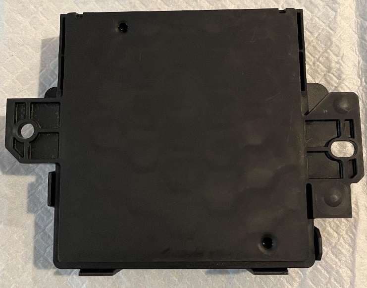
L2C0090TR
Oct 04, 2023Passive entry Keyless Go with tire pressure and door handle monitoring radio frequency module
Equipment Class
DCD - Part 15 Low Power Transmitter Below 1705 kHz
L2C0089TR
Jun 05, 2023FO3-TR903BDA
Equipment Class
DSC - Part 15 Security/Remote Control Transmitter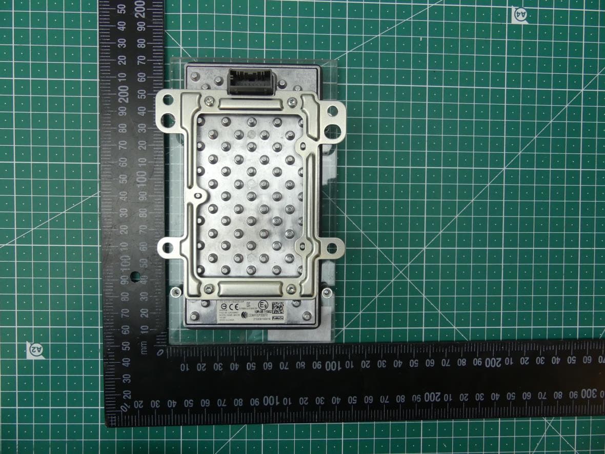
L2C0084TR
Jul 27, 2021Wireless Power Transfer Charger
Equipment Class
8CC - Part 18 Consumer Device