L2C0029TRSDARS Downconverter/Transmitter
APTIV Services US LLC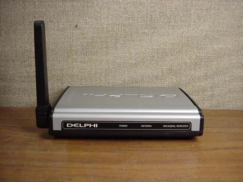
Click to zoom
Application Details
- Equipment Class
- DXX - Part 15 Low Power Communication Device Transmitter
- Date of Grant
- Jun 02, 2005
- Application Purpose
- Original Equipment
- Date of Application
- May 09, 2005
- Equipment Note
- SDARS Downconverter/Transmitter
- Frequency Range
- 909.71500000 - 920.29500000
- Company
- APTIV Services US LLC
- Country
- United States
Documents & Files
Document Text
Text extracted from the exhibit documents filed with the FCC. Open a document above to read the original.
Users Manual
Delphi XM Satellite Radio Signal Repeater User Guide For Use With Any Delphi XM Satellite Radio Unit Home Kit or Audio System SA10116-11B1 Caution:The Delphi XM Satellite Radio Signal Repeater operates on a 900 MHz frequency and may cause interference with other wireless equipment. For best results, do not operate the Delphi XM Satellite Radio Signal Repeater in the vicinity of other equipment operating at this frequency. (See page 9 for more information.) Caution:This manual contains important safety and operating information. Please read and follow the instructions in this manual. Failure to do so could result in damage to your audio system, your home, and/or other property. This device complies with Part 15 of the FCC rules. Operation is subject to the following two conditions: 1. This device may not cause harmful interference, and 2. This device must accept any interference received, including interference that may cause undesired operation. IMPORTANT: The FCC and FAA have not certified the Delphi XM ® Satellite Radio Signal Repeater for use in any aircraft(neither portable nor permanent installation). Therefore, Delphi cannot support this type of application or installation. introduction i FCC Statement This equipment has been tested and found to comply with the limits for a Class B digital device, pursuant to Part 15 of the FCC rules. These limits are designed to provide reasonable protection against harmful interference in a normal installation. This equipment generates, uses, and can radiate radio frequency energy and, if not installed and used in accordance with the instructions, may cause harmful interference to radio communications. However, there is no guarantee that interference will not occur in a particular installation. If this equipment does cause harmful interference to radio or television reception, which can be determined by turning the equipment off and on, the user is encouraged to try to correct the interference by one or more of the following measures: • Find another location for the repeater antenna (this is the smaller product of the two). • Move the transmitter and the repeater antenna farther away from each other. • Try not to share one power outlet for the transmitter and the repeater antenna. • Consult your dealer or an experienced electronics technician for help. Caution:Modifications not expressly approved by the manufacturer could void the user’s authority to operate the equipment under FCC rules. introduction ii Signal Repeater Overview introduction iii *For use with either SKYFi or SKYFi2. **For use with either Roady or Roady2. Also for use with Delphi XM SKYFi Audio System* and Delphi XM SKYFi Home Adaptor Kit.* Home antenna Transmitter antenna Delphi XM SKYFi CD Audio System* Delphi XM Roady™ Home Adaptor Kit** Delphi XM MyFi Receiver (in home stand) Welcome Thank you for purchasing a Delphi XM Satellite Radio Signal Repeater. The Signal Repeater eliminates the need for long and unsightly antenna exten- sions by retransmitting the XM signal received from the satellite up to 75 feet, providing you better access to more than 150 channels of music, news, and information, even in homes and offices where it’s not easy to locate the antenna near a window with direct access to the satellites. Plus, it allows multiple receivers located in a home or office to share a single XM antenna and signal. (Additional repeater antennas [SA10117-11P1] are available for purchase separately.) Your Delphi XM Satellite Radio Signal Repeater must be used with the enclosed connecting devices to ensure maximum performance and safety. Additional hardware and XM subscription required for reception. Not available in Alaska or Hawaii. Satellite radio reception may vary or could potentially be degraded by satellite signal obstruction. introduction iv Caution:Do not modify or alter wires or connections in any way. Shortening wires or connections may prevent proper functioning of the protection circuit. Doing so may damage your unit and will void your warranty. Caution:When using the Delphi XM Satellite Radio Signal Repeater, follow the proper safety proce- dures in your receiver’s manual. Not doing so could result in damage to your Signal Repeater, other accessories, and/or other property. Copies of Delphi satellite radio receiver user guides are available at www.shopdelphi.com. introduction v About the Delphi XM Satellite Radio Signal Repeater The Delphi XM Satellite Radio Signal Repeater is the latest accessory to accompany Delphi’s growing line of satellite radio products. The Signal Repeater helps you to enjoy XM programming even in locations without direct satellite reception. Just plug the repeater antenna into the antenna input of any XM satellite radio receiver and place it within 75 feetof the transmitter, which rebroadcasts the XM signal picked up through your home antenna. Additional repeater antennas are available separately (SA10117-11P1), allowing multiple receivers to operate off a single transmitter. Note: The Delphi XM Satellite Radio Signal Repeater may be used with any home kit or audio systemcompatible with SKYFi, SKYFi2, Roady, Roady2, or MyFi. introduction vi About Delphi Delphi is the premier provider of satellite radio products for the vehicle and home, selling more satellite digital audio receivers than any other company worldwide. A global leader in mobile electronics, vehicle components, and audio technology, Delphi created the first in-dash car radio in 1936 and continues its strong tradition of innovation in the audio industry. Now Delphi technology has helped make satellite radio a reality, and Delphi continues to expand its in-vehicleand consumer electronics technologies. With its exciting line of satellite radio products, Delphi offers a broad portfolio of products to answer a wide variety of information and entertainment needs—in the vehicle, home, office, or virtually anywhere. Visit www.shopdelphi.com for more information. About XM Established in Oc…
Text truncated - open the document above for the full version.
Attestation Statements
Re: Certification for Delphi Delco Downconverter Model: SA10116 FCC ID: L2C0029TR POWER OF ATTORNEY A letter granting Valdis V. Liepa the Power of Attorney is on file and can be provided when so requested. Re: Certification for Delphi Delco Downconverter Model: SA10116 FCC ID: L2C0029TR REQUEST FOR CONFIDENTIALITY Pursuant to 47 CRF 0.459, Delphi Delco requests that a part of the subject application be held confidential. This comprises Exhibits (5) Schematics (10) Parts List (Part of Exhibit only) Delphi Delco has spent substantial effort in developing this product and it is one of the first of its kind in industry. Having the subject information easily available to "competition" would negate the advantage they have achieved by developing this product. Not protecting the details of the design will result in financial hardship. If there are any questions regarding this request, please contact me at the above address or call 734-483-4211, fax 734-647-2106 or e-mail [email protected]. Sincerely, Valdis V. Liepa Research Scientist University of Michigan April 28, 2005 Re: Certification for Delphi Delco Downconverter Model: SA10116 FCC ID: L2C0029TR STATEMENT OF MODIFICATIONS There were no modifications made to the DUT by this test laboratory. (Also see Section 3.1 of the attached Test Report). _____________________ Valdis V. Liepa Research Scientist Re: Certification for Delphi Delco Downconverter Model: SA10116 FCC ID: L2C0029TR GENERAL PRODUCT INFORMATION The device, for which certification is pursued, has been designed by: Delphi Automotive Systems One Corporate Center Kokomo, IN 46904-9005 Frank Hirschenberger Tel: (248) 267-0098 Fax: (248) 267-8883 It will be manufactured by: Jabil Circuit Inc. 3800 Giddings Road Auburn Hills, MI 48326 Frank Hirschenberger Tel: (248) 267-0098 Fax: (248) 267-8883 Canadian Contact: Richard Wilkins c/o Delphi Energy and Chassis Systems Oshawa, Ontario L1N 7S6 [email protected] Ph. (905)644-5216
Block Diagram
Existing In Home Antenna (separate) A1 a a A3 A4 A7 IF AGC IF Preamp XM Repeater 915MHz IF AGC RF LNA A5 A6 IF-BPF IF-BPF Pad Active Mixer Micro 3 P In P Out IF A G C P Out Ref XTL Range Limiter RF-BPF Pad Pad IF-BPF Pad Pad Pad Pad P In IF A G C Split A2 Pad Pad IF-BPF Pad Pad Split RF AGC Delphi Confidential To Receiver (Ski-fi etc.) A1 a XM Repeater Antenna RF-BPF 915MHz RF AGC Pad Active Mixer Micro 3 Ref XTL RF AGC P In P Out RF AGC 915MHz Ant enna P Out Pad IF-BPF Pad Pad Discrete Notch Filter @ 915MHz & 1423.75Mhz A2 Pad Pad Delphi Confidential
Cover Letter(s)
Mr. Hirschenberger, The Commission has determined that granting a repeater to operate in the 900 MHz band under Section 15.249 of the FCC’s unlicensed Part 15 rules for retransmission of a XM satellite band signal is acceptable. We have based our decision on the following terms or conditions: 1 The repeater must meet all the requirements in Section 15.249 of the FCC Rules regardless of the level of the input SDARS satellite signal or any spurious emissions that occur in the input band. You must demonstrate that the device’s maximum field strength levels both in and out of band do not exceed the appropriate limits when any SDARS signal or spurious signal (even when such spurious signals may be above the desired SDARS input signal level) is imposed upon the device. 2 The repeater may be tested as suggested in the incoming documentation to demonstrate compliance with the FCC Rules in Section 15.249. Test data must be submitted demonstrating compliance with all appropriate rule sections for both satellite signals and spurious emissions input to the receiver. 3 Generally Part 15 repeaters are required to demodulate or recognize the incoming signal in some manner to prevent retransmission of spurious emissions and undesired signals. In this instance, we will permit a simple frequency translation to the 900 MHz band to be used in this repeater design provided the frequency band being repeated is allocated exclusively to SDARS operation and operation meets all Section 15.249 emission requirements. If you have any questions about this matter, please contact me by telephone at 301-362- 3021. Rich Fabina
Cover Letter(s)
FCC Regulatory Requirements For Design and Sale of SDARS In-Home Repeater Version 2.3 December 10, 2004 Delphi Corporation Proprietary and Confidential Page 1 of 15 FCC Regulatory Requirements For Design and Sale of SDARS In-Home Repeater Frank M. Hirschenberger [email protected] Delphi Corporation Product and Service Solutions Division Consumer Electronics Version 2.3 December 10, 2004 FCC Regulatory Requirements For Design and Sale of SDARS In-Home Repeater Version 2.3 December 10, 2004 Delphi Corporation Proprietary and Confidential Page 2 of 15 1 Scope This paper has five purposes: 1) Operational description of Delphi SDARS in-home repeater 2) Review F.C.C. regulations for device 3) Design considerations based on F.C.C. requirements 4) Provide recommendation for certification test stimulus 5) Present requests for F.C.C. rules interpretation The intended audience is specifically the F.C.C. Office of Engineering and Technology. 2 Product Overview and Operational Description Currently, Delphi is the leading maker and distributor of satellite radios in the United States, with a growing aftermarket customer base in excess of 1 million customers. One current limitation of satellite radio installations is that, generally, the SDARS antenna that is connected to the satellite radio needs to be placed at a point where the service signal is present (typically outside the house or in a window exposed to the service signal). The Delphi SDARS In-Home Repeater product is intended to overcome the limitation mentioned above such that current Delphi satellite radio customers would be able to receive the satellite radio signal (as broadcast by the service providers) at any place in their home without having to connect to the SDARS antenna. Note that the primary intention of this product is to rebroadcast the XM signal in an effort to increase sales of current Delphi aftermarket satellite radios (all of which utilize XM as service provider). Though termed as an in-home product here for identification purposes, the product is intended to also be applicable to other environments, including offices, health clubs, and malls. In this system, the S-band antenna module which feeds the transmitter has an in-band passive gain of +7 dBiC and an effective active gain of + 20 dB (low noise amplifier gain minus cable loss). The product concept involves receiving the XM SDARS signal at S-Band (centered at 2338.75 MHz), frequency-converting it to the 915 MHz ISM band, broadcasting it into the desired coverage space by radiating the SDARS signal in the 915 MHz ISM band, receiving the SDARS signal in the 915 MHz ISM band near the SDARS receiver, reconverting the signal back to S-Band, and conducting the signal into the target satellite radio via its existing antenna input. The product inherently is comprised of two units: 1) Downconverter/Transmitter FCC Regulatory Requirements For Design and Sale of SDARS In-Home Repeater Version 2.3 December 10, 2004 Delphi Corporation Proprietary and Confidential Page 3 of 15 2) Upconverter The usage of these two elements in the system is illustrated below in Figure 1. Figure 1: Delphi Repeater System Note that the SDARS spectrum consists of signals from both XM and Sirius. Both systems use QPSK digital modulation for satellites and OFDM digital modulation for terrestrial repeaters. As indicated from the system diagram, the basic tenet of the system from a bandwidth usage perspective is to take the 12.5 MHz XM SDARS spectrum and place in the 915 MHz ISM band, which has an available bandwidth of 26 MHz. The entire SDARS spectrum consisting of Sirius and XM has a bandwidth of 25 MHz. In order to meet the FCC out-of-band emission requirements, an ISM-band bandpass filter will be utilized. Spectrum shifting is performed such that the overall XM band center frequency is shifted to 915 MHz; this minimizes the XM in-band roll-off and minimizes overall transmit power requirements for functionality and range. The center frequency of the overall SDARS signal is shifted from 2332.5 MHz to 908.75 MHz with adequate accuracy such that filtering requirements are straightforward. FCC Regulatory Requirements For Design and Sale of SDARS In-Home Repeater Version 2.3 December 10, 2004 Delphi Corporation Proprietary and Confidential Page 4 of 15 The downconverter is equipped with active gain control to keep the transmit power constant (within a predetermined range) in order to maximize the range while meeting the FCC maximum transmitted power limits. The signal is intentionally radiated within the 915 MHz band. The radiated signal is received by the upconverter, which is placed in front of the pre-existent receiver. To provide a further understanding of the frequency conversion being utilized, the figures below show the received SDARS spectrum and the appearance of the spectrum when translated to the ISM band for rebroadcast. Figure 2: SDARS Spectrum FCC Regulatory Requirements For Design and Sale of SDARS In-Home Repeater Version 2.3 December 10, 2004 Delphi Corporation Proprietary and Confidential Page 5 of 15 Figure 3: SDARS Spectrum translated to ISM Band 3 F.C.C. Requirements FCC-published requirements for intentional radiators that may apply to this product as determined from Delphi research are addressed in this section. Note that unintentional radiator requirements also apply, but are not addressed in this paper. The primary source of FCC requirements at this time: Title 47 – Telecommunications, Chapter I (FCC) Applicable sections of Title 47 are referenced below. FCC Regulatory Requirements For Design and Sale of SDARS In-Home Repeater Version 2.3 December 10, 2004 Delphi Corporation Proprietary and Confidential Page 6 of 15 Based on negotiations between Delphi and F.C.C. Office of Engineering and Technology, it has been agreed in principle that Delphi is allowed to pursue certification of SDARS repeater product under F.C.C. Part 15, Section 15.249. 3.1 In-band and harmonic limi…
Text truncated - open the document above for the full version.
Cover Letter(s)
0 345 330 31 5 300 28 5 27 0 25 5 240 22 5 210 195 180 165 150 135 120 105 90 75 60 45 30 15 -3 0 -20 -10 0 dB XM , LHC P - (f=2. 333 GHz ) Phi=0° Ph i=4 5° Phi=90° P hi =135 ° Here is the plot for the XM Home Antenna. The top of the plot is the boresight gai n (towards satellite), and the bottom of the plot is th e backside gain (to house). This table shows the calculation of the average backside linear gain for the XM Home Antenna. The elevation angles are negative values as they repr esent the back of the antenna. Elevation Angle (deg) Vertical Gain (dBi) Horizontal Gain (dBi) 0 o (side) -13.1 -6.6 -5 o -12.5 -8.1 -10 o -12.0 -9.3 -15 o -12.3 -9.6 -20 o -11.2 -10.2 -25 o -9.4 -13.7 -30 o -9.4 -13.3 -35 o -9.9 -14.2 -40 o -9.4 -16.1 -45 o -9.8 -16.7 -50 o -10.3 -14.1 -55 o -9.5 -10.6 -60 o -8.6 -9.5 -65 o -9.3 -10.5 -70 o -10.2 -10.4 -75 o -12.0 -12.0 -80 o -14.2 -17.1 -85 o -15.0 -16.7 -90 o (back) -14.2 -14.2 OVERALL GAIN (dBi) -11.0
Cover Letter(s)
April 28, 2005 American Telecommunications Certification Body, Inc. 6731 Whittier Avenue Suite C110 McLean, VA 22101 Re: Certification for Delphi Delco Downconverter Model: SA10116 FCC ID: L2C0029TR Please find enclosed application materials for certification of Delphi Delco SA10116 Downconverter. Note: 1) portions of this submittal are filed Confidential 2) a list of the modifications made is provided in Attestations. If there are any questions regarding the application or testing performed, please contact me at the above address or call 734-483-4211, fax 734-647-2106, or e-mail [email protected]. Sincerely, Valdis V. Liepa Research Scientist
Cover Letter(s)
May 4, 2005 RE: Delphi Delco Electronics Systems FCC ID: L2C0029TR The following is in response to the comments made on the above application: 1) Where is 2 part statement on label? The ID label Exhibit has been updated the show the Interference statement clearly. It is molded into the DUT case just below the label. 2) Grant should not report power for this. I believe this is with regard to the following question. 3) This is NOT a DTS device....It should be approved only under 15.249 It was unknown to us the the DTS designation was restricted to 15.247 devices. Per our conversation with you, we have modified the application forms to use the Equipment Classification: DXX 4) Section 6.1 of the report should likely cite 15.109. The report has been updated to cite 15.109. 5) LISN setup does not appear to be in compliance with ANSI C63.4 positioning/mounting requirements. Please review. The cable from the DUT to the LISN appears to have come loose from its bundle. We have retested the DUT for conducted emissions and found no change in the conducted emissions. An updated test setup photo has been provided and new conducted emissions data has been added to the test report. In addition, we have moved our LISN networks behind the test table, rather than under the test table, to better ensure compliance with the 80 cm rule in C63.4 as requested. 6) Additionally, the Figure 6.15 suggests a 6 dB difference with the voltage dropped to 85% (see 15.31(e)). This appears a little larger than expected and also suggests that some of the in band data or harmonics may be dramatically affected and possible exceed the limits under these conditions. Please review. After examination by the manufacturer, it was determined that a 5V voltage regulator (U404) was unable remain stable as the supply voltage from the transformer decreased due to supply voltage variation. Once the supply voltage from the transformer decreased such that the dropout voltage on the regulator could no longer be maintained, the regulator would cycle the DUT on and off irregularly. To resolve the issue, the 5V regulator was replaced with another regulator (same package) with a reduced dropout voltage. The Parts List exhibit has been updated to reflect the changes made. The DUT with a new regulator was measured by our laboratory for conducted and radiated emissions. New conducted emissions are provided in the revised test report, along with a new voltage variation plot. Digital radiated emissions did not show any change. Emissions at the fundamental were tested and exhibited a change of less than 0.2 dB, justifying that the data already collected is valid for demonstration of compliance.
Cover Letter(s)
FCC ID: L2C0029TR Applicant: Delphi Delco Electronics Systems Correspondence Reference Number: 20352 731 Confirmation Number: TC836412 Date of Original Email: 05/24/2005 Subject: FCC Equipment Authorization System The following is in response to the comments made on the above referenced application. 1) What is the center frequency of the lowest channel of the device and the center frequency of the highest channel of the device? The requested frequency range should be modified accordingly. The device under test is a repeater, translating the XM radio band into the 902-928 MHz ISM band, and does not necessarily operate on a “channel” basis. However, the highest and lowest intentionally radiated XM satellite signals are centered at 909.715 MHz, and 920.295 MHz, respectively, after translation from the XM radio band (LO is 1423.75 MHz). Note that the DUT may unintentionally radiate any spurious emission falling into the XM radio band. Thus, it is possible that the DUT may transmit at any frequency between 902 and 928 MHz, and it seems appropriate that the DUT be listed to operate across the entire 902-928 MHz band, centered at 915 MHz. 2) Provide a Bandwidth plot of the device. The bandwidth of the DUT emission is dependant on the input signal. The 6 dB bandwidth is 4.0 MHz for the simulated XM satellite signal(s) (see Fig. 6.5-6.6), and 5.2 MHz for the simulated XM terrestrial signal(s) (see Fig. 6.8). Since it is not possible to predict all spurious emissions that may fall in the XM band and be translated to the ISM band, it is not straightforward to determine an operating bandwidth for the DUT. 3) Indicate how compliance of the bandedge requirements was met with the device operating on the lowest and highest channels. Band edge radiated emissions were measured at the band edge, and demonstrated to comply with the field strength limits at those frequencies, as discussed in section 6.3 of the test report. These measurements were made for all required stimuli as agreed upon by the FCC in the test procedure included with this filing. 4) It appears that the field strength levels in the 902-928 MHz band were made only in the Vertical polarization. Was testing performed in the Horizontal polarization? If not, submit required data. Horizontal and vertical measurements were made for all orientations of the DUT. Worst case emissions at the fundamental were obtained in the vertical polarization and are reported in the test report. Horizontal measurements were significantly lower, and thus not reported.
Operational Description
FCC Regulatory Requirements For Design and Sale of SDARS In-Home Repeater Version 2.3 December 10, 2004 Delphi Corporation Proprietary and Confidential Page 2 of 15 1 Scope This paper has five purposes: 1) Operational description of Delphi SDARS in-home repeater 2) Review F.C.C. regulations for device 3) Design considerations based on F.C.C. requirements 4) Provide recommendation for certification test stimulus 5) Present requests for F.C.C. rules interpretation The intended audience is specifically the F.C.C. Office of Engineering and Technology. 2 Product Overview and Operational Description Currently, Delphi is the leading maker and distributor of satellite radios in the United States, with a growing aftermarket customer base in excess of 1 million customers. One current limitation of satellite radio installations is that, generally, the SDARS antenna that is connected to the satellite radio needs to be placed at a point where the service signal is present (typically outside the house or in a window exposed to the service signal). The Delphi SDARS In-Home Repeater product is intended to overcome the limitation mentioned above such that current Delphi satellite radio customers would be able to receive the satellite radio signal (as broadcast by the service providers) at any place in their home without having to connect to the SDARS antenna. Note that the primary intention of this product is to rebroadcast the XM signal in an effort to increase sales of current Delphi aftermarket satellite radios (all of which utilize XM as service provider). Though termed as an in-home product here for identification purposes, the product is intended to also be applicable to other environments, including offices, health clubs, and malls. In this system, the S-band antenna module which feeds the transmitter has an in-band passive gain of +7 dBiC and an effective active gain of + 20 dB (low noise amplifier gain minus cable loss). The product concept involves receiving the XM SDARS signal at S-Band (centered at 2338.75 MHz), frequency-converting it to the 915 MHz ISM band, broadcasting it into the desired coverage space by radiating the SDARS signal in the 915 MHz ISM band, receiving the SDARS signal in the 915 MHz ISM band near the SDARS receiver, reconverting the signal back to S-Band, and conducting the signal into the target satellite radio via its existing antenna input. The product inherently is comprised of two units: 1) Downconverter/Transmitter
Test Report
The University of Michigan Radiation Laboratory 3228 EECS Building Ann Arbor, MI 48109-2122 Tel: (734) 764-0500 Measured Radio Frequency Emissions From Delphi SDARS Downconverter/Transmitter Model(s): SA10116 Report No. 415031-246 May 9, 2005 Copyright © 2005 For: Delphi Automotive Systems One Corporate Center Kokomo, IN 46904-9005 Contact: Frank Hirschenberger Tel: (248) 267-0098 Fax: (248) 267-8883 [email protected] PO: Verbal Tests supervised by: Measurements made by: Report approved by: _____________________ Joseph D. Brunett Valdis V. Liepa Research Scientist Summary Tests for compliance with FCC Regulations, according to Part 15.249, were performed on Delphi Automotive Systems SDARS Downconverter/Transmitter. In testing completed on April 18, 2005, the device tested met the emission limits at the fundamental by more than 2.5 dB, at the band edges by more than 1.1 dB, and by 4.1 dB at the harmonics. Radiated digital emissions from circuitry used to enable the operation of the device meet the FCC/IC Class B limit by more than 2.9 dB. AC power line conducted emissions meet the FCC/IC Class B limit by more than 2.2 dB. 2 1. Introduction Delphi Automotive Systems SDARS Downconverter/Transmitter was tested for compliance with FCC Regulations, Part 15, adopted under Docket 87-389, April 18, 1989, and with Industry Canada RSS-210, Issue 5, dated November 10, 2001. The tests were performed at the University of Michigan Radiation Laboratory Willow Run Test Range following the procedures described in ANSI C63.4-2003 "Methods of Measurement of Radio-Noise Emissions from Low-Voltage Electrical and Electronic Equipment in the Range of 9 kHz to 40 GHz" and the document, "FCC Regulatory Requirements for Design and Sale of SDARS In-Home Repeater v.2.3" The Site description and attenuation characteristics of the Open Site facility are on file with FCC Laboratory, Columbia, Maryland (FCC Reg. No: 91050) and with Industry Canada, Ottawa, ON (File Ref. No: IC 2057). 2. Test Equipment Used The pertinent test equipment commonly used in our facility for measurements is listed in Table 2.1 below. The middle column identifies the specific equipment used in these tests. Table 2.1. Test Equipment. Test Instrument Eqpt. Used Manufacturer/Model Spectrum Analyzer (0.1-1500 MHz) Hewlett-Packard, 182T/8558B Spectrum Analyzer (9kHz-22GHz) Hewlett-Packard 8592L, SN: 3710A00856 Spectrum Analyzer (9kHz-26GHz) X Hewlett-Packard 8593E, SN: 3412A01131 Spectrum Analyzer (9kHz-26GHz) Hewlett-Packard 8563E, SN: 3310A01174 Spectrum Analyzer (9kHz-40GHz) Hewlett-Packard 8564E, SN: 3745A01031 Power Meter Hewlett-Packard, 432A Power Meter Anritsu, ML4803A/MP Harmonic Mixer (40-60 GHz) Hewlett-Packard 11970U, SN: 2332A00500 Harmonic Mixer (60-90 GHz) Pacific Millimeter Prod., VN, SN: 47 Harmonic Mixer (75-110 GHz) Hewlett-Packard 11970W, SN: 2521A00179 Harmonic Mixer (140-220 GHz) Pacific Millimeter Prod., GMA, SN: 26 C-band horn (4 - 6.2 GHz) X University of Michigan, NRL design Xn-band horn (6.0 – 8.4 GHz) X University of Michigan, NRL design X-band horn (8.2- 12.4 GHz) Narda 640 X-band horn (8.2- 12.4 GHz) X Scientific Atlanta , 12-8.2, SN: 730 K-band horn (18-26.5 GHz) FXR, Inc., K638KF Ka-band horn (26.5-40 GHz) FXR, Inc., U638A U-band horn (40-60 GHz) Custom Microwave, HO19 V-band horn (60-90 GHz) Custom Microwave, HO12 Bicone Antenna (30-250 MHz) X University of Michigan, RLBC-1 Bicone Antenna (200-1000 MHz) X University of Michigan, RLBC-2 Dipole Antenna Set (30-1000 MHz) X University of Michigan, RLDP-1,-2,-3 Dipole Antenna Set (30-1000 MHz) EMCO 2131C, SN: 992 Active Rod Antenna (30 Hz-50 MHz) EMCO 3301B, SN: 3223 Active Loop Antenna (30 Hz-50 MHz) EMCO 6502, SN:2855 Ridge-horn Antenna (300-5000 MHz) X University of Michigan Amplifier (5-1000 MHz) Avantek, A11-1, A25-1S Amplifier (5-4500 MHz) X Avantek Amplifier (4.5-13 GHz) X Avantek, AFT-12665 Amplifier (6-18 GHz) Trek Amplifier (18-26.5 GHz) Avantek, AMT-26158-13 Vector Signal Generator X Agilent E4438C Signal Generator X Rohde & Schwarz SMIQ 03S LISN (50 μH) X University of Michigan Signal Generator (0.1-2060 MHz) Hewlett-Packard, 8657B 3 3. Configuration and Identification of Device Under Test The Device Under Test (DUT) is a 902-928 MHz Downconverter/Transmitter. The device directly translates XM Satellite signals in the SDARS band centered at 2338.75 MHz to the 902-928 MHz ISM band. The size of the DUT is 6(W) x 4(H) x 1(D) inches. During testing, a pair of signal generators capable of XM satellite radio simulation were used to excite the…
Text truncated - open the document above for the full version.
Contact Information
Applicant
Brian W Johnson(Engineering Group Manager)
Technical Contact
University of Michigan/EECSValdis Liepa
[email protected]734-483-4211
1301 Beal Avenue · Ann Arbor, Michigan · United States
Test Firm
University of MichiganValdis Liepa
Technical Specifications
| # | Rule Parts | Frequency Range | Power Output |
|---|---|---|---|
| 1 | 15C | 909.715 MHz - 920.295 MHz | - |
Other Applications from APTIV Services US LLC
L2CSRR6PS
Apr 09, 2024SRR6PS
Equipment Class
VRD - Part 95 Vehicular Radar SystemsL2C0093TR
Mar 12, 2024Wireless Charging Module
Equipment Class
8CC - Part 18 Consumer Device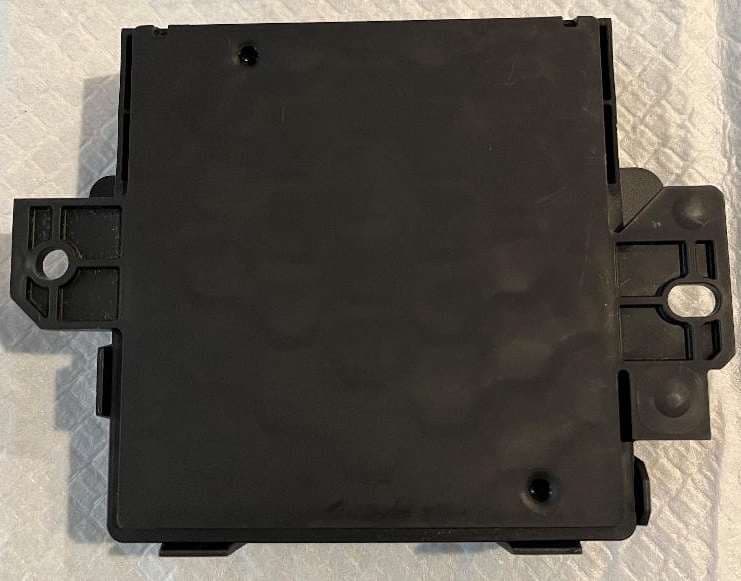
L2C0090TR
Oct 04, 2023Passive entry Keyless Go with tire pressure and door handle monitoring radio frequency module
Equipment Class
DCD - Part 15 Low Power Transmitter Below 1705 kHz
L2C0089TR
Jun 05, 2023FO3-TR903BDA
Equipment Class
DSC - Part 15 Security/Remote Control Transmitter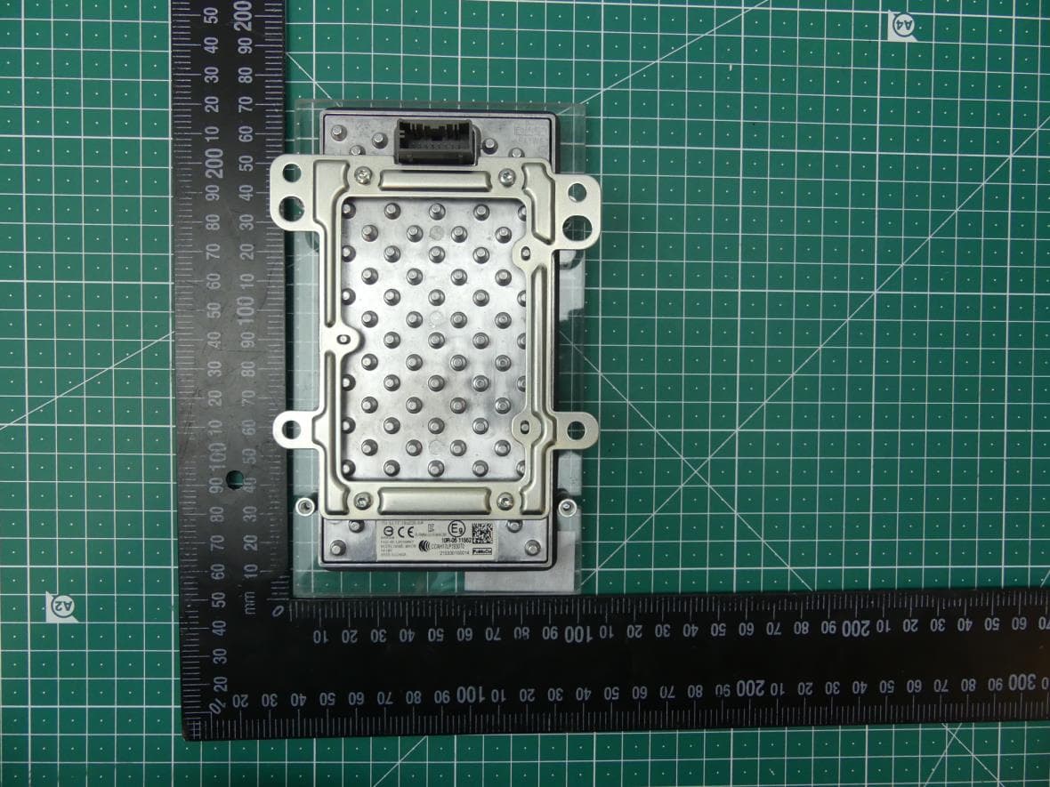
L2C0084TR
Jul 27, 2021Wireless Power Transfer Charger
Equipment Class
8CC - Part 18 Consumer Device