L2C0045TRAM/FM/CD with Bluetooth
APTIV Services US LLC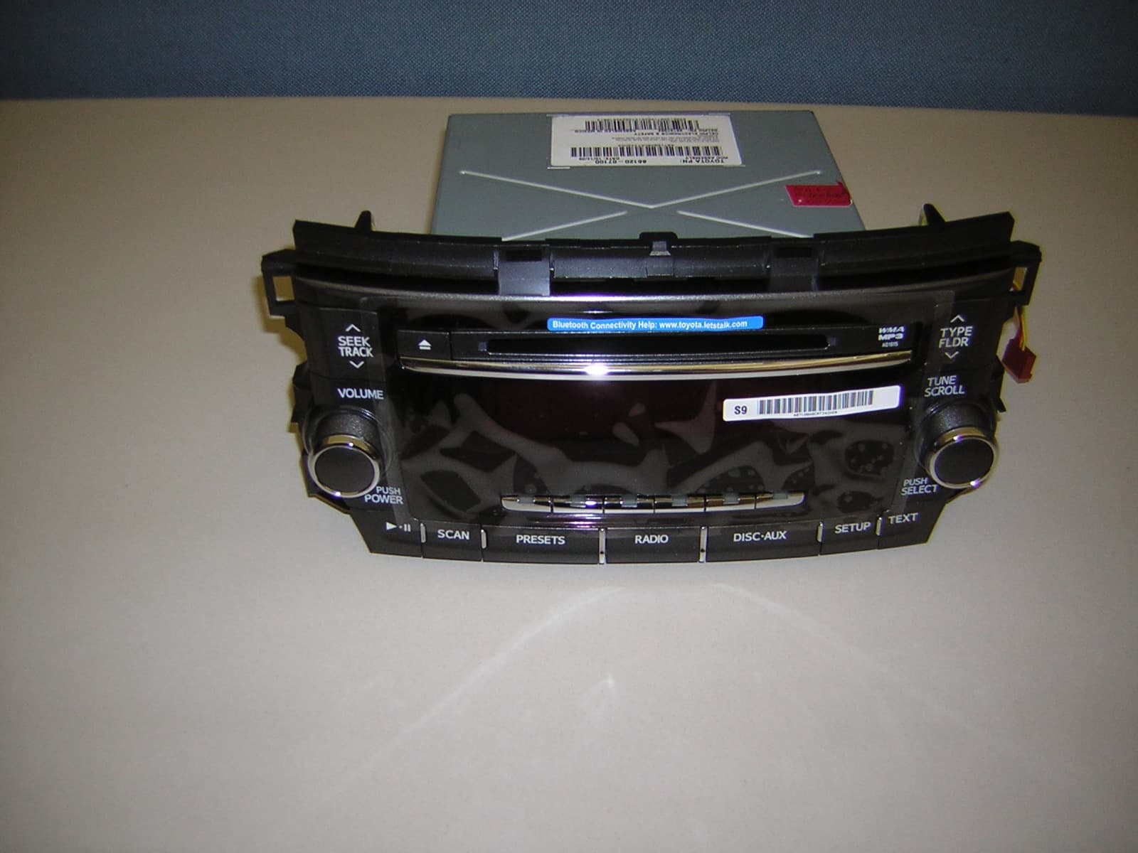
Click to zoom
Application Details
- Equipment Class
- DSS - Part 15 Spread Spectrum Transmitter
- Date of Grant
- Dec 07, 2009
- Application Purpose
- Original Equipment
- Date of Application
- Dec 07, 2009
- Equipment Note
- AM/FM/CD with Bluetooth
- Frequency Range
- 2402.00000000 - 2480.00000000
- Company
- APTIV Services US LLC
- Country
- United States
Documents & Files
Document Text
Text extracted from the exhibit documents filed with the FCC. Open a document above to read the original.
Users Manual
232 3-3. Using the hands-free phone system (for cellular phone) Hands-free phone system (for cellular phone) features (CD player with changer only) nConditions affecting operation The hands-free phone system may not operate normally in the following situ- ations: lThe cellular phone is turned off, or located outside the service area. lThe cellular phone has a low battery. lThe cellular phone is not connected to the system. lThe cellular phone is behind the seat or in the glove box, or metal mate- rial covers or touches the phone. nWhen transferring ownership of the vehicle Be sure to initialize the system to prevent personal data from being improp- erly accessed. nRequired profiles for the cellular phone lHFP (Hands Free Profile) Ver. 1.0 lOPP (Object Push Profile) Ver. 1.1 This system supports Bluetooth ® , which allows you to make or receive calls without using cables to connect a cellular phone and the system, and without operating the cellular phone. Owners of models equipped with a navigation system should refer to the “Navigation System Owner's Manual”. TitlePage Using the hands-free phone systemP. 235 Making a phone callP. 244 Setting a cellular phoneP. 248 Security and system setupP. 253 Using the phone bookP. 257 233 3-3. Using the hands-free phone system (for cellular phone) 3 Interior features nTrademark owned by Bluetooth SIG. Inc. nCertification for the hands-free phone system NOTE: This device complies with Part 15 of the FCC Rules and RSS-210 of industry Canada. Operation is subject to the following two conditions: (1) This device may not cause harmful interference, and (2) This device must accept any interference received, including interference that may cause undesired oper- ation. NOTICE: This equipment has been tested and found to comply with the limits for a Class B digital device, pursuant to Part 15 of the FCC Rules. These limits are designed to provide reasonable protection against harmful interference in a residential installation. This equipment generates, uses and can radiate radio frequency energy and, if not installed and used in accordance with the instructions, may cause harmful interference to radio communications. How- ever, there is no guarantee that interference will not occur in a particular installation. If this equipment does cause harmful interference to radio or television reception, which can be determined by turning the equipment off and on, the user is encouraged to try to correct the interference by one or more of the following measures: lReorient or relocate the receiving antenna. lIncrease the separation between the equipment and receiver. lConnect the equipment into an outlet on a circuit different from that to which the receiver is connected. lConsult the dealer or an experienced radio/TV technician for help. FCC ID: HYQBTAU01A IC ID: 1551A- 234 3-3. Using the hands-free phone system (for cellular phone) FCC WARNING: Changes or modifications in construction not expressly approved by the party responsible for compliance could void the user's authority to operate the equipment. CAUTION: Radio Frequency Radiation Exposure This equipment complies with FCC radiation exposure limits set forth for uncontrolled equipment and meets the FCC radio frequency (RF) Exposure Guidelines in Supplement C to OET65. This equipment has very low levels of RF energy that it deemed to comply without maximum permissive expo- sure evaluation (MPE). But it is desirable that it should be installed and oper- ated with at least 20 cm and more between the radiator and person’s body (excluding extremities: hands, wrists, feet and legs). Co-location: This transmitter must not be co-located or operated in conjunction with any other antenna or transmitter. CAUTION nCaution while driving Do not use a cellular phone, or connect the Bluetooth ® phone. NOTICE nTo prevent damage to a cellular phone Do not leave a cellular phone in the vehicle. The temperature inside may become high resulting in damage to the phone. 235 3-3. Using the hands-free phone system (for cellular phone) 3 Interior features Using the hands-free phone system (for cellular phone) nAudio unit Displays such items as message, name, and phone number Lower-case characters and special characters, such as an umlaut, cannot be dis- played. Press and hold: Displays information that is too long to be displayed at one time on the screen Selects speed dials Selects items such as menu or number Turn: Selects an item Press: Inputs the selected item Displays Bluetooth ® con- nection condition If BT is not displayed, the hands-free phone system cannot be used. Displays the reception level 236 3-3. Using the hands-free phone system (for cellular phone) nSteering wheel Type A Volume The voice guidance volume cannot be adjusted by using this button. Hands-free phone system off/ends a call/refuses a call (on-hook switch) Hands-free phone system on/starts a call (off-hook switch) Press: Voice command sys- tem on Press and hold: Voice com- mand system off (talk switch) 237 3-3. Using the hands-free phone system (for cellular phone) 3 Interior features Type B Volume The voice guidance volume cannot be adjusted by using this button. Hands-free phone system on/starts a call (off-hook switch) Hands-free phone system off/ends a call/refuses a call (on-hook switch) Press: Voice command sys- tem on Press and hold: Voice com- mand system off (talk switch) nMicrophone 238 3-3. Using the hands-free phone system (for cellular phone) Operating the system by using a voice command By following voice guidance instructions output from the speaker, voice commands can be given to allow for operation of the hands- free phone system without checking the display or operating . nOperation procedure when using a voice command Press the talk switch and say the command for a desired function. (→P. 240) nAuxiliary commands when using a voice command The following auxiliary commands can be used when operating the system using a voice command: Cancel: Exits …
Text truncated - open the document above for the full version.
Cover Letter(s)
5725 Delphi Drive Troy, Michigan 48098-2815 USA World Headquarters & Customer Center 11/11/09 FCC ID: L2C0045TR, IC: 3432A-0045TR Request for Confidentiality In accordance with 47 C.F.R. Section 0.459, we, Delphi Corporation, hereby request confidentiality for the block diagram, schematic and product description presented for certification. In support of the Request for Confidentiality, the following is stated: Enclosed within this application is technical information which we deem to be trade secrets and proprietary. If made public, the information might be used to our disadvantage. To assist in assuring that we receive the full value of our product and protect its competitive posture, we respectfully request this grant of confidentiality. Kevin Henderson Delphi Corporation Electronics and Safety Division
Cover Letter(s)
5725 Delphi Drive Troy, Michigan 48098-2815 USA World Headquarters & Customer Center 11/13/2009 Elite Electronic Engineering, Inc. 1516 Centre Circle Downers Grove, IL 60515 To Whom It May Concern: Elite Electronic Engineering, Inc. is authorized to act on our behalf, until otherwise notified, for applications to Elite Electronic Engineering, Inc. We certify that we are not subject to denial of federal benefits, that includes FCC benefits, pursuant to Section 5301 of the Anti-Drug Abuse Act of 1988, U.S.C. 862. Further, no party, as defined in 47 CFR 1.2002 (b) to the application is subject to denial of federal benefits, that includes FCC benefits. Thank you. Regards, Kevin Henderson Delphi Electronics and Safety
Test Report
Engineering Test Report No. 0903412-01 Measurement of RF Interference from a Toyota Bluetooth Radio Transmitter, Part Number 28137382 For : Delphi One Corporate Center Kokomo, IN 46904 P.O. No. : 450968916 Date Tested : November 9 through 12, 2009 Test Personnel : Daniel Crowder Specification : FCC "Code of Federal Regulations" Title 47 Part 15, Subpart C, Section 15.247 for Frequency Hopping and Digitally Modulated Intentional Radiators Operating within the 2400-2483.5MHz : RSS-210, Annex 8, for Frequency Hopping and Digital Modulation Systems Operating in the Band 2400 – 2483.5MHz : RSS-Gen Test Report By : Daniel Crowder EMC Test Engineer Approved By : Raymond J. Klouda Registered Professional Engineer of Illinois - 44894 Elite Electronic Engineering Inc. 1516 Centre Circle Downers Grove, IL 60515 Tel : (630) 495-9770 Fax: (630) 495-9785 www.elitetest.com Engineering Test Report No. 0903412-01 TABLE OF CONTENTS PARAGRAPH DESCRIPTION OF CONTENTS PAGE NO. THIS REPORT SHALL NOT BE REPRODUCED, EXCEPT IN FULL, WITHOUT THE WRITTEN APPROVAL OF ELITE ELECTRONIC ENGINEERING INCORPORATED. Page 2 of 57 1 INTRODUCTION .......................................................................................................................................... 5 1.1 Scope of Tests..................................................................................................................................... 5 1.2 Purpose ............................................................................................................................................... 5 1.3 Deviations, Additions and Exclusions.................................................................................................. 5 1.4 EMC Laboratory Identification ............................................................................................................. 5 1.5 Laboratory Conditions ......................................................................................................................... 5 2 APPLICABLE DOCUMENTS ....................................................................................................................... 5 3 TEST ITEM SET-UP AND OPERATION ..................................................................................................... 6 3.1 General Description ............................................................................................................................. 6 3.1.1 Power Input ..................................................................................................................................... 6 3.1.2 Grounding........................................................................................................................................ 6 3.1.3 Peripheral Equipment...................................................................................................................... 6 3.1.4 Interconnect Cables ........................................................................................................................ 6 3.2 Operational Mode ................................................................................................................................ 6 3.3 Test Item Modifications........................................................................................................................ 6 4 TEST EQUIPMENT ...................................................................................................................................... 6 4.1 Test Equipment List ............................................................................................................................. 6 4.2 Calibration Traceability ........................................................................................................................ 6 5 REQUIREMENTS, PROCEDURES AND RESULTS .................................................................................. 7 5.1 Powerline Conducted Emissions ......................................................................................................... 7 5.1.1 Requirements .................................................................................................................................. 7 5.2 20dB Bandwidth................................................................................................................................... 7 5.2.1 Requirement.................................................................................................................................... 7 5.2.2 Procedures ...................................................................................................................................... 7 5.2.3 Results ............................................................................................................................................ 7 5.3 Carrier Frequency Separation: ............................................................................................................ 7 5.3.1 Requirements .................................................................................................................................. 7 5.3.2 Procedures ...................................................................................................................................... 7 5.3.3 Results ............................................................................................................................................ 7 5.4 Number of Hopping Frequencies ........................................................................................................ 8 5.4.1 Requirements .................................................................................................................................. 8 5.4.2 Procedures ...................................................................................................................................... 8 5.4.3 Results ...................................................................................…
Text truncated - open the document above for the full version.
Test Setup Photos
Engineering Test Report No. 0903412-01 Page 18 of 57 Figure 3 Test Set-up for Radiated Emissions – 2GHz to 18GHz, Horizontal Polarization Test Set-up for Radiated Emissions – 2GHz to 18GHz, Vertical Polarization Engineering Test Report No. 0903412-01 Page 19 of 57 Figure 4 Test Set-up for Radiated Emissions, 18GHz to 25GHz, Horizontal Polarization Test Set-up for Radiated Emissions, 18GHz to 25GHz, Vertical Polarization
Contact Information
Applicant
Brian W Johnson(Engineering Group Manager)
Technical Contact
Delphi Delco Electronics SystemsSteve P Alverson
[email protected]7654518548
2151 E. Lincoln Rd. · Kokomo, Indiana · United States
Non-Technical Contact
Delphi Delco Electronics SystemsThomas B Finderburk
[email protected]7654518475
Test Firm
Elite Electronic Engineering Inc.Kevin Halpin
Technical Specifications
| # | Rule Parts | Frequency Range | Power Output |
|---|---|---|---|
| 1 | 15C | 2.40 GHz - 2.48 GHz | 1.00 mW |
Other Applications from APTIV Services US LLC
L2CSRR6PS
Apr 09, 2024SRR6PS
Equipment Class
VRD - Part 95 Vehicular Radar SystemsL2C0093TR
Mar 12, 2024Wireless Charging Module
Equipment Class
8CC - Part 18 Consumer Device
L2C0090TR
Oct 04, 2023Passive entry Keyless Go with tire pressure and door handle monitoring radio frequency module
Equipment Class
DCD - Part 15 Low Power Transmitter Below 1705 kHz
L2C0089TR
Jun 05, 2023FO3-TR903BDA
Equipment Class
DSC - Part 15 Security/Remote Control Transmitter
L2C0084TR
Jul 27, 2021Wireless Power Transfer Charger
Equipment Class
8CC - Part 18 Consumer Device