L2C0050TRICR
APTIV Services US LLC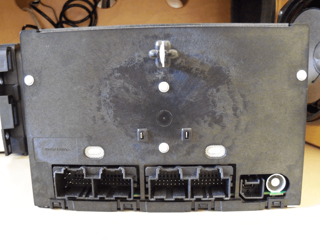
Click to zoom
Application Details
- Equipment Class
- DSS - Part 15 Spread Spectrum Transmitter
- Date of Grant
- May 21, 2012
- Application Purpose
- Original Equipment
- Date of Application
- May 21, 2012
- Equipment Note
- ICR
- Frequency Range
- 2402.00000000 - 2480.00000000
- Company
- APTIV Services US LLC
- Country
- United States
Documents & Files
Document Text
Text extracted from the exhibit documents filed with the FCC. Open a document above to read the original.
Users Manual
1 BLUETOOTH® PAIRING, PANDORA® AND STREAMING AUDIO (TO THE RADIO) • Bluetooth PAIRING – From the HOME page, select SETTINGS. You may have to go through 2 to 3 home pages, depending on where you’ve placed the SETTINGS icon. (Yes, this can be customized). – You may also touch the PTT SWC button, and say “Pair Phone” which will then take you immediately to Bluetooth Device List Menu below. – Select Bluetooth Device List – Touch New Device, and begin a scan on your phone/device – Find “Buick Enclave, Chevrolet Traverse or GMC Acadia” on your phone and follow the instructions to complete the pairing. Also select Yes on the radio and affirm the pairing on the phone as well; you will see a 6-digit code that matches between the radio and device. – Once paired, the device will appear in the list in the radio. If it does not automatically connect, touch in the screen button on the radio of the device desired. A check mark in the box and the Bluetooth® symbol will also appear. Your device should also show the connection confirmation. – If an authorization request appears on your phone, choose accept always to enable automatic connection to this device upon vehicle start-up. Notes: – A Bluetooth-enabled phone and an audio playback device can be paired to the system for hands-free phone calling and mp3 music playing. – Pairing only needs to be completed once, unless the pairing information on the cell phone changes or the cell phone is deleted from the system. (Secure phones may require authorization approval before auto-connect). Choose “Accept Always” as it may apply during pairing. – Only one paired cell phone or device can be connected to the Bluetooth system at a time, although up to 10 devices can be paired. When pairing multiple devices for the first time, shut the Bluetooth power OFF on the currently connected device in order to keep it from interfering with the pairing of the second, third, fourth, etc. device. Once you have completed paring all devices, turn the Bluetooth power back ON in the device you choose to be connected with. – To connect to a different paired phone or device, go back to the Bluetooth Device List and then select the device of choice. Ensure that device’s BT power has been turned on. – If user disconnects from the radio via the device, re-connection can only occur using the radio HMI. – Multiple paired devices with their Bluetooth power on approaching the vehicle may 2 result in the undesired device connecting automatically. Verify the intended device is connected prior to your trip, or leave the Bluetooth power off on the device you don’t want to automatically connect to. • PANDORA® – All phones must be Bluetooth-paired to the radio in order to operate Pandora ® (and Stitcher® soon). – Blackberry, Android , and iPhones with the Pandora® application installed will allow Pandora® App to be run via the radio HMI. “PANDORA ACCESSORY” with an up and down arrow will be seen on the phone display when full connection is completed, indicating control on the radio is enabled. At this point, the only App control from the phone is to quit the App. – iPhones stream their Pandora ® audio through Bluetooth at this time; (song artist and title is shown also) but control of the App from the radio is not yet available using Bluetooth. So, when you connect your iPhone using a USB cable, the Pandora ® App running on the phone will be able to be controlled on the radio. Song information, Artist and Album Art* will be displayed as well as familiar Pandora® controls like thumbs up/down. * Note album art for iPhone only comes when connected by wire at this time. – Depending on the phone, it may take a long time for the app to launch from the radio if the app is not already launched on the phone. So the happy path is to launch the app on the phone first, then select the source app from the radio. • BLUETOOTH AUDIO STREAMING: – When BT Audio source is selected from Radio, the BT phone/device will launch its internal media player and start playing its audio files through vehicle speakers via Bluetooth. Both iPods and iPhones can do this as well when paired, but for i- devices, the artist, song title and album art is only available when tethered to the USB port. HANDS FREE PHONE • Phone Menu Access - Start at HOME page, touch PHONE icon and then select item of choice. 3
Cover Letter(s)
May 14 th , 2012 To: Federal Communications Commission Authorization and Evaluation division Subject: Request for Confidentiality for DELPHI ICR Radio (FCC ID - L2C0050TR) Pursuant to 47 CRF 0.457(d) and 0.459, Delphi requests that a part of the subject application be held confidential. Type of Confidentiality requested Exhibit Type File name Permanent Schematics ICR_Schematic.pdf Permanent Parts List/BOM ICR_Parts List.pdf Permanent Block Diagram ICR_Block Diagram.pdf Permanent Theory of Operation ICR_Theory of Operation.pdf Permanent Technical Description ICR_Technical Overview.pdf Short-Term User Manual ICR_User’s Manual Excerpt.pdf Short-Term Internal Photos ICR_ Internal Photos.pdf Short-Term External Photos ICR_ External Photos.pdf Delphi has spent substantial effort in developing this product and it is one of the first of its kind in industry. Having the subject information easily available to "competition" would negate the advantage they have achieved by developing this product. Not protecting the details of the design will result in financial hardship. Permanent Confidentiality: Delphi requests the exhibits listed above as permanently confidential be permanently withheld from public review. Short-Term Confidentiality: Delphi requests the exhibits selected above as short term confidential be withheld from public view for a period of 45 days from the date of the Grant of Equipment Authorization and prior to marketing. Sincerely, Brian W. Johnson EGM - EMC Design Group Delphi Electronics & Safety M/S CTC 2E 2151 E. Lincoln Rd Kokomo IN 46902
External Photos
Page 1 of 3 External Photos: ICR 28275847 Front Back Page 2 of 3 SIDE A SIDE B Page 3 of 3 Top Bottom
ID Label/Location Info
Page 1 of 3 ICR FCC/IC ID LABEL & LOCATION FCC ID Label Artwork FCC ID Label Location Note: At the time of submission of the FCC Certification application, a label had not been printed yet with the FCC and IC IDs. The ID numbers are as follows: FCC ID: L2C0050TR IC ID: 3432A-0050TR Page 2 of 3 ICR LABEL DRAWING Page 3 of 3 EXCERPT OF RADIO ASSEMBLY DRAWING - MOCKUP OF LABEL DRAWING Formal Drawings will be released in June of 2012
Internal Photos
Page 1 of 4 Internal Photos: ICR 28275847 Faceplate & Keyboard Keyboard Top Components Page 2 of 4 Keyboard Bottom Components Top & Side Covers & Mechanism Page 3 of 4 Mechanism & Top Components Top Components Page 4 of 4 Bottom Components & Cover Bottom Components
Test Report
Engineering Test Report No. 1200330-01 Measurement of RF Emissions from a 28275847 Car Radio Transmitter For Delphi Electronics and Safety One Corporate Center Kokomo, IN 46904 P.O. Number 451426107 Date Tested February 7 through 24, 2012 Test Personnel Richard King Test Specification FCC "Code of Federal Regulations" Title 47, Part 15, Subpart C, Section 15.247 for Frequency Hopping Spread Spectrum Intentional Radiators within The bands 2400-2483.5MHz Industry Canada RSS-GEN Industry Canada RSS-210 Test Report By: Richard King EMC Engineer Approved By: Raymond J. Klouda Registered Professional Engineer of Illinois - 44894 Elite Electronic Engineering, Inc. 1516 Centre Circle Downers Grove, IL 60515 Tel : (630) 495-9770 Fax: (630) 495-9785 www.elitetest.com Engineering Test Report No. 1200330-01 TABLE OF CONTENTS PARAGRAPH DESCRIPTION OF CONTENTS PAGE NO. THIS REPORT SHALL NOT BE REPRODUCED, EXCEPT IN FULL, WITHOUT THE WRITTEN APPROVAL OF ELITE ELECTRONIC ENGINEERING INCORPORATED. Page 2 of 66 1. Introduction ................................................................................................................................................... 5 1.1. Scope of Tests ..................................................................................................................................... 5 1.2. Purpose ............................................................................................................................................... 5 1.3. Deviations, Additions and Exclusions .................................................................................................. 5 1.4. EMC Laboratory Identification ............................................................................................................. 5 1.5. Laboratory Conditions.......................................................................................................................... 5 2. Applicable Documents .................................................................................................................................. 5 3. EUT Setup and Operation ............................................................................................................................ 6 3.1. General Description ............................................................................................................................. 6 3.1.1. Power Input ................................................................................................................................. 6 3.1.2. Peripheral Equipment ................................................................................................................. 6 3.1.3. Signal Input/Output Leads .......................................................................................................... 6 3.1.4. Grounding ................................................................................................................................... 6 3.2. Operational Mode ................................................................................................................................ 6 3.3. EUT Modifications ................................................................................................................................ 6 4. Test Facility and Test Instrumentation ......................................................................................................... 6 4.1. Shielded Enclosure .............................................................................................................................. 6 4.2. Test Instrumentation ............................................................................................................................ 7 4.3. Calibration Traceability ........................................................................................................................ 7 4.4. Measurement Uncertainty ................................................................................................................... 7 5. Test Procedures ........................................................................................................................................... 7 5.1. Powerline Conducted Emissions ......................................................................................................... 7 5.1.1. Requirements .............................................................................................................................. 7 5.2. 20dB Bandwidth ................................................................................................................................... 7 5.2.1. Requirement................................................................................................................................ 7 5.2.2. Procedures .................................................................................................................................. 7 5.2.3. Results ........................................................................................................................................ 7 5.3. Carrier Frequency Separation ............................................................................................................. 8 5.3.1. Requirements .............................................................................................................................. 8 5.3.2. Procedures .................................................................................................................................. 8 5.3.3. Results ........................................................................................................................................ 8 5.4. Number of Hopping Frequencies ......................................................................................................... 8 5.4.1. Requirements .............................................................................................................................. 8 5…
Text truncated - open the document above for the full version.
Test Setup Photos
Engineering Test Report No. 1200330-01 Page 18 of 66 Figure 2 Test Setup for Radiated Emissions, 30MHz to 1GHz – Horizontal Polarization Test Setup for Radiated Emissions, 30MHz to 1GHz – Vertical Polarization Engineering Test Report No. 1200330-01 Page 19 of 66 Figure 3 Test Setup for Radiated Emissions, above 1GHz – Horizontal Polarization Test Setup for Radiated Emissions, above 1GHz – Vertical Polarization
Contact Information
Applicant
Brian W Johnson(Engineering Group Manager)
Technical Contact
Delphi Electronics & SafetyLum Forfeke
[email protected]7654517991
2151 E. Lincoln Rd. · Kokomo, Indiana · United States
Non-Technical Contact
Delphi Electronics & SafetyLum Forfeke
[email protected]7654517991
Test Firm
Elite Electronic Engineering Inc.Kevin Halpin
Technical Specifications
| # | Rule Parts | Frequency Range | Power Output |
|---|---|---|---|
| 1 | 15C | 2.40 GHz - 2.48 GHz | 178.00 µW |
Other Applications from APTIV Services US LLC
L2CSRR6PS
Apr 09, 2024SRR6PS
Equipment Class
VRD - Part 95 Vehicular Radar SystemsL2C0093TR
Mar 12, 2024Wireless Charging Module
Equipment Class
8CC - Part 18 Consumer Device
L2C0090TR
Oct 04, 2023Passive entry Keyless Go with tire pressure and door handle monitoring radio frequency module
Equipment Class
DCD - Part 15 Low Power Transmitter Below 1705 kHz
L2C0089TR
Jun 05, 2023FO3-TR903BDA
Equipment Class
DSC - Part 15 Security/Remote Control Transmitter
L2C0084TR
Jul 27, 2021Wireless Power Transfer Charger
Equipment Class
8CC - Part 18 Consumer Device