L3Z210019Anti shoplifting system
Gunnebo Gateway AB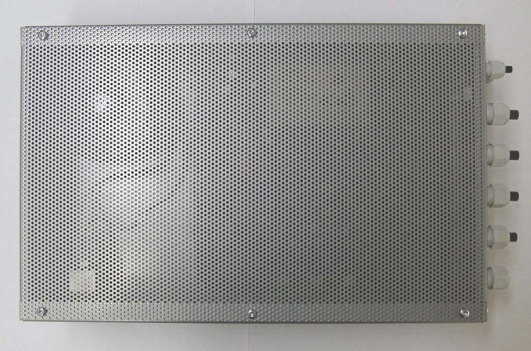
Click to zoom
Application Details
- Equipment Class
- FAP - Part 15 Anti-Pilferage Device
- Date of Grant
- Dec 16, 2015
- Application Purpose
- Original Equipment
- Date of Application
- Dec 16, 2015
- Equipment Note
- Anti shoplifting system
- Frequency Range
- 0.05800000 - 0.05800000
- Company
- Gunnebo Gateway AB
- Country
- Sweden
Documents & Files
Document Text
Text extracted from the exhibit documents filed with the FCC. Open a document above to read the original.
External Photos
1(8) External photos Controller AM 2(8) 3(8) 4(8) 5(8) Doorgate AM Antenna 6(8) Prime AM Antenna 7(8) Premium AM Antenna 8(8) Silver AM antenna
ID Label/Location Info
1(1) Label and label location Controller AM
Parts List/Tune Up Info
STOREPROTECT Doorgate AM Wall-Mounted Antenna perfect for limited space The StoreProtect series gives you a full range of top quality anti-shoplifting systems, working with the industry standard AM technology. Top quality in both antenna-design and function, with the ability to access and control the system via the secure, online remote-service solution. The StoreProtect-family comes in a full range of designs in various colors. All systems are engineered and produced in Sweden with high quality components. DOORGATE AM ANTENNA FEATURES • Silver-painted MDF antenna frame • Wall/doorframe mounted. ANTENNA SPECIFICATIONS • Width 280 mm • Height 1700 mm • Thickness 32 mm CONTROLLER BOX SPECIFICATIONS • Connects up to nine StoreProtect AM antennas at ones • Quick and easy mounting • Quality metal case • 115V, 230V versions available • Remote service (Remote Service Controller required) • CE, FCC, UL Approvals Gunnebo Gateway AB is a Swedish supplier of antitheft systems for the retail sector worldwide. We are the only company to develop, manufacture and market solutions built on every existing form of Electronic Article Surveillance (EAS) technology. Gunnebo Gateway AB Member of the Gunnebo Security Group Skogvaktaregatan 3 SE-591 62 Motala Sweden +46 141 21 50 70 www.gateway-security.com STOREPROTECT Doorgate AM AUTHORIZED DEALER 59,3 1698,6 1580 100 390 940 1330 42 32 20 280 O 6 ( 4 x ) STOREPROTECT Premium AM Slim and discrete design The StoreProtect series gives you a full range of top quality anti-shoplifting systems, working with the industry standard AM technology. Top quality in both antenna-design and function, with the ability to access and control the system via the secure, online remote-service solution. The StoreProtect-family comes in a full range of designs in various colors. All systems are engineered and produced in Sweden with high quality components. PREMIUM AM ANTENNA FEATURES • Metal antenna frame • Plastic side-panels • Optional printed logo on the side-panels • Customized side-panels colours • Narrow base ANTENNA SPECIFICATIONS • Width 303 mm • Height 1546 mm • Thickness 50 mm • Thickness at base 54 mm ADD-ONS • Antenna protection buffers Gunnebo Gateway AB is a Swedish supplier of antitheft systems for the retail sector worldwide. We are the only company to develop, manufacture and market solutions built on every existing form of Electronic Article Surveillance (EAS) technology. Gunnebo Gateway AB Member of the Gunnebo Security Group Skogvaktaregatan 3 SE-591 62 Motala Sweden +46 141 21 50 70 www.gateway-security.com CONTROLLER BOX SPECIFICATIONS • Connects up to nine StoreProtect AM antennas at ones • Quick and easy mounting • Quality metal case • 115V, 230V versions available • Remote service (Remote Service Controller required) • CE, FCC, UL Approvals STOREPROTECT Premium AM AUTHORIZED DEALER 186 17 O 1 2 ( 2 x ) 1546,4 308 12 54 49,6 303 STOREPROTECT Prime AM Stylish and cost effective The StoreProtect series gives you a full range of top quality anti-shoplifting systems, working with the industry standard AM technology. Top quality in both antenna-design and function, with the ability to access and control the system via the secure, online remote-service solution. The StoreProtect-family comes in a full range of designs in various colors. All systems are engineered and produced in Sweden with high quality components. PRIME AM ANTENNA FEATURES • Metal frame • Narrow base ANTENNA SPECIFICATIONS • Width 446 mm • Height 1515 mm • Thickness 59 mm • Thickness at base 64 mm ADD-ONS • Antenna protection buffers Gunnebo Gateway AB is a Swedish supplier of antitheft systems for the retail sector worldwide. We are the only company to develop, manufacture and market solutions built on every existing form of Electronic Article Surveillance (EAS) technology. Gunnebo Gateway AB Member of the Gunnebo Security Group Skogvaktaregatan 3 SE-591 62 Motala Sweden +46 141 21 50 70 www.gateway-security.com CONTROLLER BOX SPECIFICATIONS • Connects up to nine StoreProtect AM antennas at ones • Quick and easy mounting • Quality metal case • 115V, 230V versions available • Remote service (Remote Service Controller required) • CE, FCC, UL Approvals STOREPROTECT Prime AM AUTHORIZED DEALER 260 12 O 12 ( 2 x ) 445,5 12,7 1514,7 63,5 431,8 59 STOREPROTECT Silver AM Excellent detection and modern design The StoreProtect series gives you a full range of top quality anti-shoplifting systems, working with the industry standard AM technology. Top quality in both antenna-design and function, with the ability to access and control the system via the secure, online remote-service solution. The StoreProtect-family comes in a full range of designs in various colors. All systems are engineered and produced in Sweden with high quality components. SILVER AM ANTENNA FEATURES • Silver-painted MDF antenna frame • Scratch resistant metal covers • Several base cover options • Optional AD-holder for advertising ANTENNA SPECIFICATIONS • Width 430 mm • Height 1585 mm • Thickness 32 mm • Thickness at base 152 mm ADD-ONS • Antenna protection buffers Gunnebo Gateway AB is a Swedish supplier of antitheft systems for the retail sector worldwide. We are the only company to develop, manufacture and market solutions built on every existing form of Electronic Article Surveillance (EAS) technology. Gunnebo Gateway AB Member of the Gunnebo Security Group Skogvaktaregatan 3 SE-591 62 Motala Sweden +46 141 21 50 70 www.gateway-security.com CONTROLLER BOX SPECIFICATIONS • Connects up to nine StoreProtect AM antennas at ones • Quick and easy mounting • Quality metal case • 115V, 230V versions available • Remote service (Remote Service Controller required) • CE, FCC, UL Approvals STOREPROTECT Silver AM AUTHORIZED DEALER
Test Report
Test report No. 1300375-6, Ed. 4 Page 2 (18) Revision History Edition Date Description 1 2013-07-08 First release 2 2014-09-19 Model name updated 3 2015-09-25 New edition where the test results are compared to current requirements (new edition of RSS-Gen). Update is made under project no. 1507653. 4 2015-12-07 Updated to ANSI C63.10-2013 Test report No. 1300375-6, Ed. 4 Page 3 (18) CONTENTS Page 1 Client information................................................................................................................ 4 2 Equipment under test (EUT) ............................................................................................... 4 2.1 Identification of the EUT according to the manufacturer/client declaration ............. 4 2.2 FCC ID and IC ID ..................................................................................................... 4 2.3 Additional hardware information about the EUT ...................................................... 4 2.4 Modification during the tests .................................................................................... 4 3 Test specifications .............................................................................................................. 5 3.1 Standards ................................................................................................................. 5 3.2 Additions, deviations and exclusions from standards .............................................. 5 3.3 Test site .................................................................................................................... 5 3.4 Test conditions ......................................................................................................... 5 4 Test summary ..................................................................................................................... 6 5 AC Line Conducted Emission, 150 kHz to 30 MHz ............................................................ 8 5.1 Requirement ............................................................................................................. 8 5.2 Test setup details ..................................................................................................... 8 5.3 Test data .................................................................................................................. 9 5.4 Test equipment ...................................................................................................... 10 6 Radiated test below 30 MHz ............................................................................................ 11 6.1 Requirement ........................................................................................................... 11 6.2 Test setup details ................................................................................................... 11 6.3 Test data ................................................................................................................ 13 6.4 Test equipment ...................................................................................................... 14 7 Radiated emissions measurements from 30 MHz to 1000MHz ....................................... 15 7.1 Requirement ........................................................................................................... 15 7.2 Test setup details ................................................................................................... 15 7.3 Test data ................................................................................................................ 16 7.4 Test equipment ...................................................................................................... 16 8 Uncertainties summary ..................................................................................................... 17 9 Photo of the EUT .............................................................................................................. 18 Test report No. 1300375-6, Ed. 4 Page 4 (18) 1 CLIENT INFORMATION The EUT has been tested by request of Company: Gunnebo Gateway AB Box 346 591 24 Motala SVERIGE Name of contact: Claes Kemmer 2 EQUIPMENT UNDER TEST (EUT) 2.1 Identification of the EUT according to the manufacturer/client declaration Equipment: Anti shoplifting system Type/Model: Controller AM with Doorgate AM antenna Brand name: Gateway Serial number: No serial number Manufacturer: Gunnebo Gateway AB Transmitter frequency range: 58 kHz Highest clock frequency: 24 MHz Frequency agile or hopping: Yes No Antenna: Internal antenna External antenna Antenna connector: None, internal antenna Yes, type Temperature range: Category I (General): -20°C to +55°C Category II (Portable equipment): -10°C to +55°C Category III (Equipment for normal indoor use): +5°C to +35°C Other: Transmitter stand by mode supported: Yes No 2.2 FCC ID and IC ID The EUT is requested to be certified with the FCC ID: L3Z210019 The EUT is requested to be certified with the IC ID: 8083A-210019 2.3 Additional hardware information about the EUT The EUT consists of the following units: Unit Type Part number Serial number 3 antennas Doorgate AM 107047 No serial number Electronic box Controller AM 107030 No serial number Alarm tag A3 TAG AM 108036 No serial number 2.4 Modification during the tests No modifications have been made during the tests. Test report No. 1300375-6, Ed. 4 Page 5 (18) 3 TEST SPECIFICATIONS 3.1 Standards 47 CFR Part 15, Subpart B, Unintentional radiators 47 CFR Part 15, Subpart C, Intentional radiators ICES-001, Issue 4 (June 2006) RSS-Gen, Issue 4 (Nov 2014) RSS-210, Issue 8 (Dec 2010) Test methods in: ANSI C63.10-2013: American National Standard of Procedures for Compliance Testing of Unlicensed Wireless Devices 3.2 Additions, deviations and exclusions from standards EUT is floor standing, but it is placed up to 10 cm above the ground plane during the measurements. No other additions, deviations or exclusions have been…
Text truncated - open the document above for the full version.
Test Report
Test report No. 1300375-5, Ed. 4 Page 2 (18) Revision History Edition Date Description 1 2013-07-08 First release 2 2014-09-19 Model name updated 3 2015-09-25 New edition where the test results are compared to current requirements (new edition of RSS-Gen). Update is made under project no. 1507653. 4 2015-12-07 Updated to ANSI C63.10-2013. Test report No. 1300375-5, Ed. 4 Page 3 (18) CONTENTS Page 1 Client information................................................................................................................ 4 2 Equipment under test (EUT) ............................................................................................... 4 2.1 Identification of the EUT according to the manufacturer/client declaration ............. 4 2.2 FCC ID and IC ID ..................................................................................................... 4 2.3 Additional hardware information about the EUT ...................................................... 4 2.4 Modification during the tests .................................................................................... 4 3 Test specifications .............................................................................................................. 5 3.1 Standards ................................................................................................................. 5 3.2 Additions, deviations and exclusions from standards .............................................. 5 3.3 Test site .................................................................................................................... 5 3.4 Test conditions ......................................................................................................... 5 4 Test summary ..................................................................................................................... 6 5 AC Line Conducted Emission, 150 kHz to 30 MHz ............................................................ 8 5.1 Requirement ............................................................................................................. 8 5.2 Test setup details ..................................................................................................... 8 5.3 Test data .................................................................................................................. 9 5.4 Test equipment ...................................................................................................... 10 6 Radiated test below 30 MHz ............................................................................................ 11 6.1 Requirement ........................................................................................................... 11 6.2 Test setup details ................................................................................................... 11 6.3 Test data ................................................................................................................ 13 6.4 Test equipment ...................................................................................................... 14 7 Radiated emissions measurements from 30 MHz to 1000MHz ....................................... 15 7.1 Requirement ........................................................................................................... 15 7.2 Test setup details ................................................................................................... 15 7.3 Test data ................................................................................................................ 16 7.4 Test equipment ...................................................................................................... 16 8 Uncertainties summary ..................................................................................................... 17 9 Photo of the EUT .............................................................................................................. 18 Test report No. 1300375-5, Ed. 4 Page 4 (18) 1 CLIENT INFORMATION The EUT has been tested by request of Company: Gunnebo Gateway AB Box 346 591 24 Motala SVERIGE Name of contact: Claes Kemmer 2 EQUIPMENT UNDER TEST (EUT) 2.1 Identification of the EUT according to the manufacturer/client declaration Equipment: Anti shoplifting system Type/Model: Controller AM with Premium AM antenna Brand name: Gateway Serial number: No serial number Manufacturer: Gunnebo Gateway AB Transmitter frequency range: 58 kHz Highest clock frequency: 24 MHz Frequency agile or hopping: Yes No Antenna: Internal antenna External antenna Antenna connector: None, internal antenna Yes, type Temperature range: Category I (General): -20°C to +55°C Category II (Portable equipment): -10°C to +55°C Category III (Equipment for normal indoor use): +5°C to +35°C Other: Transmitter stand by mode supported: Yes No 2.2 FCC ID and IC ID The EUT is requested to be certified with the FCC ID: L3Z210019 The EUT is requested to be certified with the IC ID: 8083A-210019 2.3 Additional hardware information about the EUT The EUT consists of the following units: Unit Type Part number Serial number 3 antennas Premium AM 107043 No serial number Electronic box Controller AM 107030 No serial number Alarm tag A3 TAG AM 108036 No serial number 2.4 Modification during the tests No modifications have been made during the tests. Test report No. 1300375-5, Ed. 4 Page 5 (18) 3 TEST SPECIFICATIONS 3.1 Standards 47 CFR Part 15, Subpart B, Unintentional radiators 47 CFR Part 15, Subpart C, Intentional radiators ICES-001, Issue 4 (June 2006) RSS-Gen, Issue 4 (Nov 2014) RSS-210, Issue 8 (Dec 2010) Test methods in: ANSI C63.10-2013: American National Standard of Procedures for Compliance Testing of Unlicensed Wireless Devices 3.2 Additions, deviations and exclusions from standards EUT is floor standing, but it is placed up to 10 cm above the ground plane during the measurements. No other additions, deviations or exclusions have been …
Text truncated - open the document above for the full version.
Test Report
Test report No. 1300375-7, Ed. 5 Page 2 (19) Revision History Edition Date Description 1 2013-07-08 First release 2 2014-03-14 Section 8, Occupied 99% bandwidth test is added 3 2014-09-19 Model name updated 4 2015-09-25 New edition where the test results are compared to current requirements (new edition of RSS-Gen). Update is made under project no. 1507653. 5 2015-12-07 Updated to ANSI C63.10-2013. Test report No. 1300375-7, Ed. 5 Page 3 (19) CONTENTS Page 1 Client information................................................................................................................ 4 2 Equipment under test (EUT) ............................................................................................... 4 2.1 Identification of the EUT according to the manufacturer/client declaration ............. 4 2.2 FCC ID and IC ID ..................................................................................................... 4 2.3 Additional hardware information about the EUT ...................................................... 4 2.4 Modification during the tests .................................................................................... 4 3 Test specifications .............................................................................................................. 5 3.1 Standards ................................................................................................................. 5 3.2 Additions, deviations and exclusions from standards .............................................. 5 3.3 Test site .................................................................................................................... 5 3.4 Test conditions ......................................................................................................... 5 4 Test summary ..................................................................................................................... 6 5 AC Line Conducted Emission, 150 kHz to 30 MHz ............................................................ 8 5.1 Requirement ............................................................................................................. 8 5.2 Test setup details ..................................................................................................... 8 5.3 Test data .................................................................................................................. 9 5.4 Test equipment ...................................................................................................... 10 6 Radiated test below 30 MHz ............................................................................................ 11 6.1 Requirement ........................................................................................................... 11 6.2 Test setup details ................................................................................................... 11 6.3 Test data ................................................................................................................ 13 6.4 Test equipment ...................................................................................................... 14 7 Radiated emissions measurements from 30 MHz to 1000MHz ....................................... 15 7.1 Requirement ........................................................................................................... 15 7.2 Test setup details ................................................................................................... 15 7.3 Test data ................................................................................................................ 16 7.4 Test equipment ...................................................................................................... 16 8 Occupied 99% bandwidth test .......................................................................................... 17 8.1 Measurement set-up .............................................................................................. 17 8.2 Test protocol .......................................................................................................... 17 8.3 Test equipment ...................................................................................................... 17 9 Uncertainties summary ..................................................................................................... 18 10 Photo of the EUT .............................................................................................................. 19 Test report No. 1300375-7, Ed. 5 Page 4 (19) 1 CLIENT INFORMATION The EUT has been tested by request of Company: Gunnebo Gateway AB Box 346 591 24 Motala SVERIGE Name of contact: Claes Kemmer 2 EQUIPMENT UNDER TEST (EUT) 2.1 Identification of the EUT according to the manufacturer/client declaration Equipment: Anti shoplifting system Type/Model: Controller AM with Prime AM antenna Brand name: Gateway Serial number: No serial number Manufacturer: Gunnebo Gateway AB Transmitter frequency range: 58 kHz Highest clock frequency: 24 MHz Frequency agile or hopping: Yes No Antenna: Internal antenna External antenna Antenna connector: None, internal antenna Yes, type Temperature range: Category I (General): -20°C to +55°C Category II (Portable equipment): -10°C to +55°C Category III (Equipment for normal indoor use): +5°C to +35°C Other: Transmitter stand by mode supported: Yes No 2.2 FCC ID and IC ID The EUT is requested to be certified with the FCC ID: L3Z210019 The EUT is requested to be certified with the IC ID: 8083A-210019 2.3 Additional hardware information about the EUT The EUT consists of the following units: Unit Type Part number Serial number 3 antennas Prime AM 107045 No serial number Electronic box Controller AM 107030 No serial number Alarm tag A3 TAG AM 108036 No serial number 2.4 Modification during the tests No modifications have been made during the tests. Test report No. 1300375-7, Ed. 5 Page 5 (19) 3 TEST …
Text truncated - open the document above for the full version.
Test Report
Test report No. 1300375-8, Ed. 4 Page 2 (17) Revision History Edition Date Description 1 2013-07-08 First release 2 2014-09-19 Model name updated 3 2015-09-25 New edition where the test results are compared to current requirements (new edition of RSS-Gen). Update is made under project no. 1507653. 4 2015-12-07 Updated to ANSI C63.10-2013. Test report No. 1300375-8, Ed. 4 Page 3 (17) CONTENTS Page 1 Client information................................................................................................................ 4 2 Equipment under test (EUT) ............................................................................................... 4 2.1 Identification of the EUT according to the manufacturer/client declaration ............. 4 2.2 FCC ID and IC ID ..................................................................................................... 4 2.3 Additional hardware information about the EUT ...................................................... 4 2.4 Modification during the tests .................................................................................... 4 3 Test specifications .............................................................................................................. 5 3.1 Standards ................................................................................................................. 5 3.2 Additions, deviations and exclusions from standards .............................................. 5 3.3 Test site .................................................................................................................... 5 3.4 Test conditions ......................................................................................................... 5 4 Test summary ..................................................................................................................... 6 5 AC Line Conducted Emission, 150 kHz to 30 MHz ............................................................ 7 5.1 Requirement ............................................................................................................. 7 5.2 Test setup details ..................................................................................................... 7 5.3 Test data .................................................................................................................. 8 5.4 Test equipment ........................................................................................................ 9 6 Radiated test below 30 MHz ............................................................................................ 10 6.1 Requirement ........................................................................................................... 10 6.2 Test setup details ................................................................................................... 10 6.3 Test data ................................................................................................................ 12 6.4 Test equipment ...................................................................................................... 13 7 Radiated emissions measurements from 30 MHz to 1000MHz ....................................... 14 7.1 Requirement ........................................................................................................... 14 7.2 Test setup details ................................................................................................... 14 7.3 Test data ................................................................................................................ 15 7.4 Test equipment ...................................................................................................... 15 8 Uncertainties summary ..................................................................................................... 16 9 Photo of the EUT .............................................................................................................. 17 Test report No. 1300375-8, Ed. 4 Page 4 (17) 1 CLIENT INFORMATION The EUT has been tested by request of Company: Gunnebo Gateway AB Box 346 591 24 Motala SVERIGE Name of contact: Claes Kemmer 2 EQUIPMENT UNDER TEST (EUT) 2.1 Identification of the EUT according to the manufacturer/client declaration Equipment: Anti shoplifting system Type/Model: Controller AM with Silver AM antenna Brand name: Gateway Serial number: No serial number Manufacturer: Gunnebo Gateway AB Transmitter frequency range: 58 kHz Highest clock frequency: 24 MHz Frequency agile or hopping: Yes No Antenna: Internal antenna External antenna Antenna connector: None, internal antenna Yes, type Temperature range: Category I (General): -20°C to +55°C Category II (Portable equipment): -10°C to +55°C Category III (Equipment for normal indoor use): +5°C to +35°C Other: Transmitter stand by mode supported: Yes No 2.2 FCC ID and IC ID The EUT is requested to be certified with the FCC ID: L3Z210019 The EUT is requested to be certified with the IC ID: 8083A-210019 2.3 Additional hardware information about the EUT The EUT consists of the following units: Unit Type Part number Serial number 3 antennas Silver AM 107040 No serial number Electronic box Controller AM 107030 No serial number Alarm tag A3 TAG AM 108036 No serial number 2.4 Modification during the tests No modifications have been made during the tests. Test report No. 1300375-8, Ed. 4 Page 5 (17) 3 TEST SPECIFICATIONS 3.1 Standards 47 CFR Part 15, Subpart B, Unintentional radiators 47 CFR Part 15, Subpart C, Intentional radiators ICES-001, Issue 4 (June 2006) RSS-Gen, Issue 4 (Nov 2014) RSS-210, Issue 8 (Dec 2010) Test methods in: ANSI C63.10-2013: American National Standard of Procedures for Compliance Testing of Unlicensed Wireless Devices 3.2 Additions, deviations and exclusions from standards EUT is floor standing, but it is placed up to 10 cm above the ground plane during the measurements. No other additions, deviations or exclusions have been m…
Text truncated - open the document above for the full version.
Test Setup Photos
1(2) Test set-up photos Control…
Text truncated - open the document above for the full version.
Contact Information
Applicant
Claes Kemmer(Technical Development MAnager)
Technical Contact
Non-Technical Contact
Gunnebo Gateway ABClaes Kemmer
[email protected]+46-141-237237
Test Firm
Intertek SEMKO ABNiklas Bostrom
Technical Specifications
| # | Rule Parts | Frequency Range | Power Output |
|---|---|---|---|
| 1 | 15C | 0.058 MHz - 0.058 MHz | - |
Other Applications from Gunnebo Gateway AB
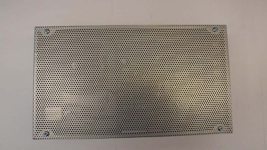
L3Z210020
Nov 30, 2015AM Deactivator Single
Equipment Class
FAP - Part 15 Anti-Pilferage Device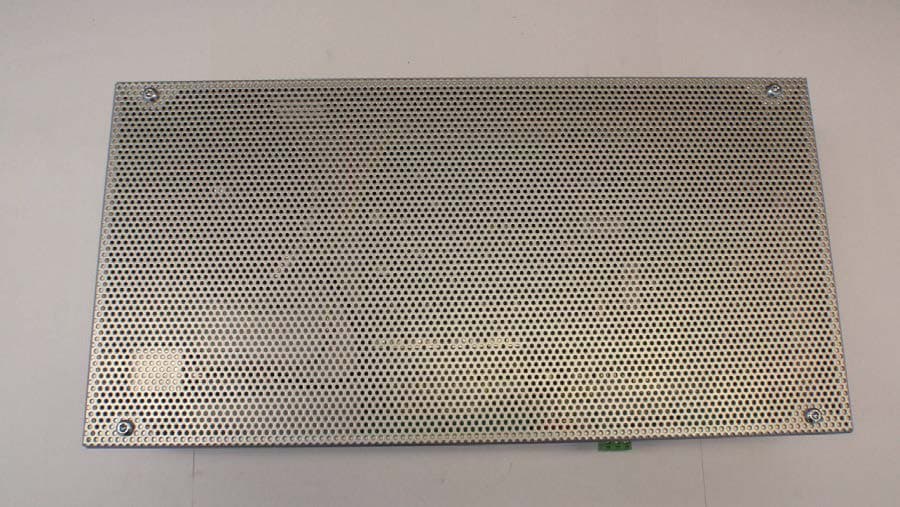
L3Z210008
Nov 30, 2015AM Deactivator Dual
Equipment Class
FAP - Part 15 Anti-Pilferage DeviceL3ZGS-201
Nov 21, 1995FAP - Part 15 Anti-Pilferage Device
Equipment Class
FAP - Part 15 Anti-Pilferage Device