L3Z210020AM Deactivator Single
Gunnebo Gateway AB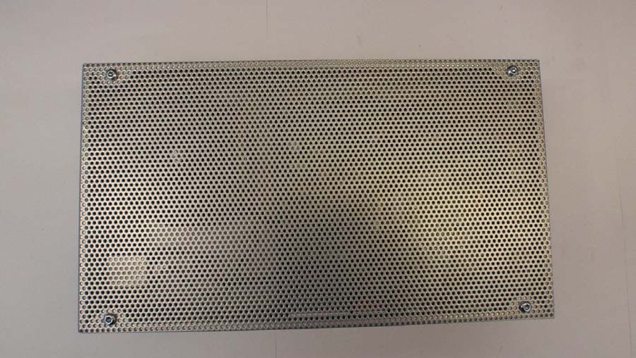
Click to zoom
Application Details
- Equipment Class
- FAP - Part 15 Anti-Pilferage Device
- Date of Grant
- Nov 30, 2015
- Application Purpose
- Original Equipment
- Date of Application
- Nov 30, 2015
- Equipment Note
- AM Deactivator Single
- Frequency Range
- 0.05800000 - 0.05800000
- Company
- Gunnebo Gateway AB
- Country
- Sweden
Documents & Files
Document Text
Text extracted from the exhibit documents filed with the FCC. Open a document above to read the original.
External Photos
1(3) External photos AM Deactivator Single AM Deactivator Single AM Deactivator Single 2(3) AM Deactivator Single AM Deactivator Single 3(3) AM Deactivator Single AM Deactivator Single
ID Label/Location Info
1(1) Label and label location AM Deactivator Single AM Deactivator Single
Internal Photos
1(3) Internal photos AM Deactivator Single AM Deactivator Single 2(3) AM Deactivator Single 3(3) AM Deactivator Single
Test Report
Test report No. 1401003-1, Ed. 2 Page 2 (19) Revision History Edition Date Description 1 2014-02-27 First release 2 2015-10-16 New edition where the test results are compared to current requirements (new edition of RSS-Gen). Test report No. 1401003-1, Ed. 2 Page 3 (19) CONTENTS Page 1 Client information................................................................................................................ 4 2 Equipment under test (EUT) ............................................................................................... 4 2.1 Identification of the EUT according to the manufacturer/client declaration ............. 4 2.2 FCC ID and IC ID ..................................................................................................... 5 2.3 Additional hardware information about the EUT ...................................................... 5 2.4 Modification during the tests .................................................................................... 5 3 Test specifications .............................................................................................................. 6 3.1 Standards ................................................................................................................. 6 3.2 Additions, deviations and exclusions from standards .............................................. 6 3.3 Test site .................................................................................................................... 6 3.4 Test conditions ......................................................................................................... 6 4 Test summary ..................................................................................................................... 7 5 AC Line Conducted Emission, 150 kHz to 30 MHz ............................................................ 8 5.1 Requirement ............................................................................................................. 8 5.2 Test setup details ..................................................................................................... 8 5.3 Test data .................................................................................................................. 9 5.4 Test equipment ...................................................................................................... 10 6 Radiated test below 30 MHz ............................................................................................ 11 6.1 Requirement ........................................................................................................... 11 6.2 Test setup details ................................................................................................... 11 6.3 Test data ................................................................................................................ 12 6.4 Test equipment ...................................................................................................... 13 7 Radiated emissions measurements from 30 MHz to 1000MHz ....................................... 14 7.1 Requirement ........................................................................................................... 14 7.2 Test setup details ................................................................................................... 14 7.3 Test data ................................................................................................................ 15 7.4 Test equipment ...................................................................................................... 15 8 Occupied 99% bandwidth test .......................................................................................... 16 8.1 Requirement ........................................................................................................... 16 8.2 Test setup details ................................................................................................... 16 8.3 Test data ................................................................................................................ 16 8.4 Test equipment ...................................................................................................... 17 9 Uncertainties summary ..................................................................................................... 18 10 Photo of the EUT .............................................................................................................. 19 Test report No. 1401003-1, Ed. 2 Page 4 (19) 1 CLIENT INFORMATION The EUT has been tested by request of Company: Gunnebo Gateway AB Skogsvaktaregatan 3 591 62 Motala SWEDEN Name of contact: Claes Kemmer 2 EQUIPMENT UNDER TEST (EUT) 2.1 Identification of the EUT according to the manufacturer/client declaration Equipment: AM deactivator Type/Model: AM deactivator Single Brand name: Gunnebo Serial number: No serial number Manufacturer: Gunnebo Gateway AB Transmitter frequency range: 58 kHz Frequency agile or hopping: Yes No Antenna: Internal antenna External antenna Antenna connector: None, internal antenna Yes, type Temperature range: Category I (General): -20°C to +55°C Category II (Portable equipment): -10°C to +55°C Category III (Equipment for normal indoor use): +5°C to +35°C Other: 0°C to +55°C Transmitter stand by mode supported: Yes No Test report No. 1401003-1, Ed. 2 Page 5 (19) 2.2 FCC ID and IC ID The EUT is requested to be certified with the FCC ID: L3Z210020 The EUT is requested to be certified with the IC ID: 8083A-210020 2.3 Additional hardware information about the EUT The EUT consists of the following units: Unit Type Part number Serial number Electronic box AM deactivator Single - - Antenna Maxi Pad - - 2.4 Modification during the tests No modifications have been made during the tests. Test report No. 1401003-1, Ed. 2 Page 6 (19) 3 TEST SPECIFICATIONS 3.1 Standards 47 CFR Part 15, Subpart C, Intentional radiators 47 CFR Part 15, Subpart B, Uni…
Text truncated - open the document above for the full version.
Test Setup Photos
1 TEST SET-UP PHOTOS AM DEACTIVATOR SINGLE Radiated test below 30MHz 2 Radiated emission 30-1000 MHz Conducted disturbance voltage
Contact Information
Applicant
Claes Kemmer(Technical Development MAnager)
Technical Contact
Non-Technical Contact
Gunnebo Gateway ABClaes Kemmer
[email protected]+46-141-237237
Test Firm
Intertek Semko ABHenriki Wikstroem
[email protected]+46 8 750 0000
Technical Specifications
| # | Rule Parts | Frequency Range | Power Output |
|---|---|---|---|
| 1 | 15C | 0.058 MHz - 0.058 MHz | - |
Other Applications from Gunnebo Gateway AB
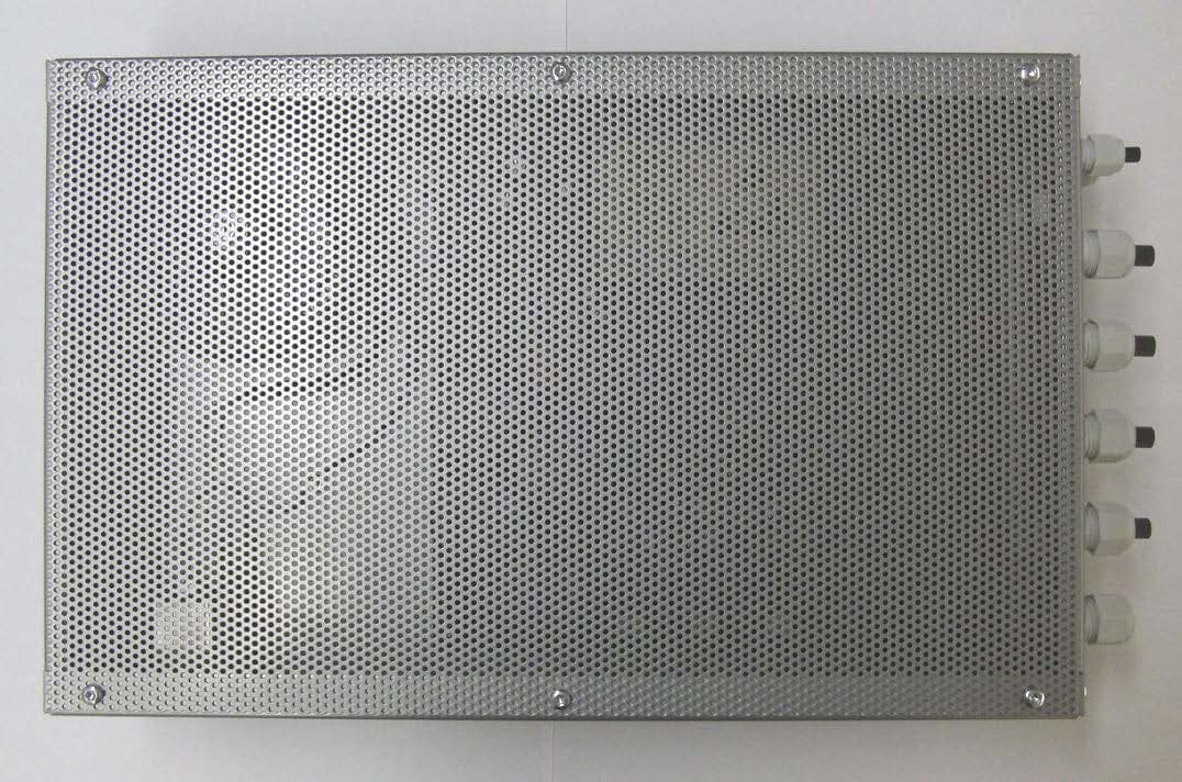
L3Z210019
Dec 16, 2015Anti shoplifting system
Equipment Class
FAP - Part 15 Anti-Pilferage Device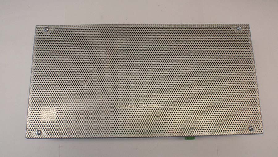
L3Z210008
Nov 30, 2015AM Deactivator Dual
Equipment Class
FAP - Part 15 Anti-Pilferage DeviceL3ZGS-201
Nov 21, 1995FAP - Part 15 Anti-Pilferage Device
Equipment Class
FAP - Part 15 Anti-Pilferage Device