L52CT-M7CEO1CT-DECT M7 Module
CeoTronics AG
Click to zoom
Application Details
- Equipment Class
- PUB - Part 15 Unlicensed PCS Base Station
- Date of Grant
- Jan 18, 2021
- Application Purpose
- Original Equipment
- Date of Application
- Jan 18, 2021
- Equipment Note
- CT-DECT M7 Module
- Frequency Range
- 1921.53600000 - 1928.44800000
- Company
- CeoTronics AG
- Country
- Germany
Documents & Files
Document Text
Text extracted from the exhibit documents filed with the FCC. Open a document above to read the original.
Users Manual
Integration Manual revision: date: author: 3 02.10.20 nh Seite 1 von 3 Integration Manual FCC-Compliance This device complies with Part 15 of the FCC Rules. Operation is subject to the following two conditions; 1. This device may not cause harmful interference, and 2. This device must accept any interference received, including interference that may cause undesired operation. Any changes or modifications NOT expressly APPROVED by CeoTronics AG could void the user's authority to operate the equipment. This RF Module is approved with the two onboard Inverse-F-type PCB antennas (W200, W201). The optional antenna connectors (X201, X202) are not functional/mounted. Limitation: The RF Module is currently approved for integration into fixed and mobile categorized end products. The usage inside portable host devices and/or simultaneous transmission with any other transmitter requires additional compliance tests and procedures. Furthermore the RF parameters of this CT-DECT Module M7 have to be evaluated in the final end product according to FCC KDB 996360 D04 to check for emissions that may occur due to intermixing of emissions with other transmitters, digital circuitry or due to physical properties of the host product (enclosure). Hereby the levels of the fundamental and worst case unwanted/spurious emissions based on the original test report of the stand-alone module shall be repeated. The regulatory compliance of the CT-DECT Module M7 does not exempt the end product from being evaluated against applicable regulatory demands; for example, FCC Part 15B criteria for unintentional radiators including appropriate equipment authorization (typically SDoC). Any notification to the end user about how to install or remove the integrated radio module is NOT allowed. Integration Manual revision: date: author: 3 02.10.20 nh Seite 2 von 3 End-product labeling requirements FCC-Compliance End products that have this CT-DECT Module M7 integrated must have a label containing at least the information shown below: Contains: FCC ID: L52CT-M7CEO1 The label must be affixed on an exterior surface of the end product such that it will be visible upon inspection. In accordance with 47 CFR § 15.19, the end-product shall bear the following statement in a conspicuous location on the device: "This device complies with Part 15 of the FCC Rules. Operation is subject to the following two conditions; (1) this device may not cause harmful interference, and (2) this device must accept any interference received, including interference that may cause undesired operation." When the device is so small or for such use that it is not practicable to place the statement above on the end product itself, the information shall be placed in a prominent location in the instruction manual or pamphlet supplied to the user or, alternatively, shall be placed on the container in which the device is marketed. Integration Manual revision: date: author: 3 02.10.20 nh Seite 3 von 3 End-product user manual instructions (Statements to be added inside the user manual of the end products equipped with the CT-DECT Module M7) FCC Compliance This device complies with part 15 of the FCC Rules. Operation is subject to the following two conditions: (1) This device may not cause harmful interference, and (2) this device must accept any interference received, including interference that may cause undesired operation. Any changes or modifications NOT expressly APPROVED by CeoTronics AG could void the user's authority to operate the equipment. Example for fixed and mobile host devices: This equipment complies with FCC radiation exposure limits set forth for a controlled environment and should be installed and operated with minimum distance 20 cm between the radiator (antenna) and your body.
Cover Letter(s)
PHOENIX TESTLAB GmbH Product Certification Königswinkel 10 D 32825 BlombergDate: 25 August 2020 Subject: REQUEST FOR FCC MODULAR TRANSMITTER APPROVAL FCC ID: L52CT-M7CEO1 To Whom It May Concern: The Grantee CeoTronics AG hereby requests☐ a modular /☒limited modular approval. In CFR47 §15.212 “Modular Transmitters” and KDB 996369 D01 “Module Equip Auth Guide” there are following eight numbered requirements defined: 1. The radio elements must have the radio frequency circuitry shielded. Physical components and tuning capacitor(s) may be located external to the shield, but must be on the module assembly. This requirement is fulfilled – please refer to external photo exhibit. 2. The modular transmitter must have buffered modulation/data inputs (if such inputs are provided) to ensure that the module will comply with part 15 requirements under conditions of excessive data rates or over-modulation. This requirement is fulfilled – please refer to Block Diagram & Schematics 3. The modular transmitter must have its own power supply regulation on the module. This requirement is fulfilled – please refer to Block Diagram & Schematics 4. The module must contain a permanently attached antenna, or contain a unique antenna connector, and be marketed and operated only with specific antenna(s), per §§ 15.203, 15.204(b), 15.204(c), 15.212(a), 2.929(b). This request is fulfilled – there are two inverted F-type PCB antennas.The two UFL-antenna connectors on the bottom side of the PCBs will not be used/mounted at all. 5. The module must demonstrate compliance in a stand-alone configuration. This request is fulfilled – please refer to test report and testsetup photo. 6. The modular transmitter must be equipped with either a permanently affixed label or must be capable of electronically displaying its FCC identification number (KDB 784748). This request is fulfilled – please refer to lable location exhibit. 7. The modular transmitter must comply with any specific rule or operating requirements applicable to the transmitter and the manufacturer must provide adequate instructions along with the module to explain any such requirements. The Grantee declares that this device will exclusively integrated by the Grantee himself into his own host devices and not be marketed to any 3 rd party. Therefore, a reduced Integration Manual is submitted for the certification process and Limited Modular Approval applied. 8. The modular transmitter must comply with any applicable RF exposure requirements in its final configuration. This request is fulfilled for integration into fixed or mobile categorized host devices.For usage inside portable host devices appropriate RF exposure compliance (SAR) and equipment authorization procedures need to be applied. Yours sincerely, PHOENIX TESTLAB GmbH Graduated Approval Engineer International Type Approval
Cover Letter(s)
PHOENIX TESTLAB GmbH Königswinkel 10 D 32825 Blomberg Date: 09.10.2020 FCC ID: L52CT-M7CEO1 Subject: Antenna on module information To Whom it may concern, CeoTronics declares that the DECT module M7 with FCC ID mentioned above uses two antennas that are mounted on the module itself. The optional UFL antenna connectors are not mounted and there are no external antennas that are connectable. Yours sincerely, Horst Dreinert International Type Approval PHOENIX TESTLAB GmbH
Cover Letter(s)
Long/Short-term Confidentiality Request PHOENIX TESTLAB GmbHDate: 18 January 2021 Product Certification Königswinkel 10 D 32825 Blomberg FCC ID: L52CT-M7CEO1 To Whom It May Concerns, Pursuant to sections 0.457(d) and 0.459 of CFR 47 and to avoid premature release of sensitive information prior to marketing or release of the product to the public, we hereby request long-term confidential treatment of information accompanying this application as outlined below: ☒ Schematics☒ Parts List ☒ Block Diagram☒ Tune-Up Info ☒ Operational Description In addition we hereby request the following exhibits contained in this application to be temporarily (short-term confidentiality) withheld from the public disclosure ☐ for an initial period of days☐ until:☐ not applicable ☐ External Photos☐ Test Setup Photos ☐ Internal Photos☐ Users Manual The above materials contain trade secrets and proprietary information not customarily released to the public. The public disclosure of these matters might be harmful to the applicant and provide unjustified benefits to its competitors. The applicant understands that pursuant to rule 0.457(d), disclosure of this application and all accompanying documentation will not be made before the date of the GRANT for this application. If you have any questions, please feel free to contact me. Yours sincerely, Signatory Horst Dreinert Graduated Approval Engineer
Cover Letter(s)
Power of Attorney Please be advised that due to the Power of Attorney from CeoTronics given to me Uwe Dollitz, PHOENIX TESTLAB GmbH, I authorize the following person from PHOENIX TESTLAB GmbH: ·Mr. Horst Dreinert to act on our the behalf of our customer in all matters relating to application for equipment authorization, including the signing of all documents relating to these matters and in-country-testing. PHOENIX TESTLAB GmbH has the permission to use the technical documents for the approvals for the following device: Customer / AddressCeoTronics AG Adam-Opel Strasse 6 63322 Roedermark Germany Model name/-number:CT-DECT Multi M7 Product description:Wireless communication Radio Brand name:CeoTronics AG Unless future correspondence from CeoTronics, please extend full cooperation to PHOENIX TESTLAB GmbH regarding matters to the above mentioned product until 30.08.2021. Sincerely Yours, Contact personUwe Dollitz Position in the companySection Manager, International Type Approval Date of signatory2020-04-20 ___________________________ Signatory
ID Label/Location Info
PHOENIX TESTLAB GmbH Phone +49(0)5235-9500-0 Königswinkel 10 Fax +49(0)5235-9500-28D-32825 Blomberg, Germany www.phoenix-testlab.de Label and Label Location for CT-DECT M7 Module Label Label Location The label is located on the bottom side of the pcb.
RF Exposure Info
PHOENIX TESTLAB GmbH Phone +49(0)5235-9500-0 Königswinkel 10 Fax +49(0)5235-9500-28D-32825 Blomberg, Germany www.phoenix-testlab.de Radio frequency radiation exposure, FCC 15.319 (i) Document No. : VO028524 DECT M7 MPE calculation_FCC For customer project : VO028524 DECT M7 Device under Test Model Name : CT-DECT M7 Module FCC ID : L52CT-M7CEO1 Customer CeoTronics AG FCC Registration Number (FRN Number): 0005-8988-95 63322 Roedermark Adam-Opel Strasse 6 Germany Device description : CT-DECT M7 Module UPCS devices are subject to the radio frequency radiation exposure requirements specified in FCC parts 1.1307 (b), 2.1091 and 2.1093, as appropriate. All equipment shall be considered to operate in a general population / uncontrolled environment. Consideration of radio frequency radiation exposure for EUT is done as MPE calculation as shown below. The EUT is considered as mobile device according to OET Bulletin 65, Edition – 97 -01 Therefore a distance to human body of min. 20 cm is determined. PHOENIX TESTLAB GmbH Phone +49(0)5235-9500-0 Königswinkel 10 Fax +49(0)5235-9500-28D-32825 Blomberg, Germany www.phoenix-testlab.de The internal antennas used for this mobile transmitter must provide a separation distance of at least 20 cm from all persons and must not be co-located or operating in conjunction with any other antenna or transmitter except in accordance wit the FCC multitransmitter policy. A safety statement concerning the minimum separation distances from enclosure of the device will be integrated in the user ́s manual to provide end-users with transmitter operating conditions for satisfying RF exposure compliance. Calculation : S = EIRP / 4 pi R 2 EIRP calculation based on max permitted conducted peak power = 20.2 dBm EIRP for antenna 1 (gain 3.5dBi) : 23.7 dBm EIRP for antenna 2 (gain 1.5dBi) : 21.7 dBm For calculation of S only the higher value for antenna 1 will be considered : EIRP Radiated power [dBm] 23.7 EIRP Radiated power [mW] 234.42 R Distance [cm] 20 S calculated Power density [mW/cm 2 ] 0.0467 Limit USA * Limit [mW/cm 2 ] 1.0 * The limit is taken from 47 CFR Ch. I (e-CFR November 9, 2020) Table 1 to §1.1310(e)(1) - Limits for Maximum Permissible Exposure (MPE). (ii) Lim its for General Population/Uncontrolled Exposure 1,500-100,000 MHz The calculated value is well below the limit. Verdict : Pass 2020-05-19 Horst Dreinert
Test Report
Test Report No.: G0M-1702-6254-TFC15DFP-V03 Eurofins Product Service GmbH Storkower Str. 38c, D-15526 Reichenwalde, Germany Page 1 of 86 FCC TEST REPORT FCC 47 CFR Part 15D Unlicensed Personal Communication Service Devices Industry Canada RSS-213 2GHz License-exempt Personal Communications Service Devices (LE-PCS) Report Reference No. .................... : G0M-1702-6254-TFC15DFP-V03 Testing Laboratory ........................ : Eurofins Product Service GmbH Address ............................................ : Storkower Str. 38c 15526 Reichenwalde Germany Accreditation .................................... : DAkkS - Registration number : D-PL-12092-01-03 (ISED) ISED Testing Laboratory site: 3470A-2 DAkkS - Registration number : D-PL-12092-01-04 (FCC) FCC Filed Test Laboratory, Des.-No.: DE0008 FCC Filed Test Laboratory, Reg.-No.: 129507 Applicant’s name ........................... : Ceotronics AG Address ............................................ : Adam-Opel-Str. 6 63322 Rödermark GERMANY Test specification: Standard ........................................... : 47 CFR Part 15D 47 CFR Part 15C 47 CFR Part 15B RSS-213, Issue 3, 2015-03 Test scope.............. ....................... : partial Radio compliance test Equipment under test (EUT): Product description DECT/UPCS - Modul Model No. CT-DECT M7 Additional Model(s) None Brand Name(s) CeoTronics Hardware version M7_0 DECT_HPB_1001421 Firmware / Software version V1.0.0 FCC-ID: L52CT-M7CEO1 IC: 9714A-CTM7CEO1 Test result Passed Test Report No.: G0M-1702-6254-TFC15DFP-V03 Eurofins Product Service GmbH Storkower Str. 38c, D-15526 Reichenwalde, Germany Page 3 of 86 Version History Version Issue Date Remarks Revised by 01 2017-05-23 Initial Release 02 2020-02-11 Replaced document: G0M-1702-6254-TFC15DFP-V01 Replaced by: G0M-1702-6254-TFC15DFP-V02 Reason: Page 1 & 6: FCC ID and IC added Page 6: PMN, HVIN, and FVIN added. Page 10: Pictures EUT without shielding changed. Page 11 & 12: Test setup pictures radiated emission corrected. W. Treffke 03 2020-10-12 Replaced document: G0M-1702-6254-TFC15DFP-V02 Replaced by: G0M-1702-6254-TFC15DFP-V03 Reason: Page 1: FCC Filed Test Laboratory updated Page 15: Day added to calibration information C. Weber Test Report No.: G0M-1702-6254-TFC15DFP-V03 Eurofins Product Service GmbH Storkower Str. 38c, D-15526 Reichenwalde, Germany Page 4 of 86 REPORT INDEX 1 EQUIPMENT (TEST ITEM) DESCRIPTION 6 1.1 Photos - Equipment external 8 1.2 Photos - Equipment internal 9 1.3 Photos – Test setup 11 1.4 Supporting Equipment Used During Testing 13 1.5 Test Modes 14 1.6 Test Equipment Used During Testing 15 1.7 Sample emission level calculation 16 2 RESULT SUMMARY 17 3 TEST CONDITIONS AND RESULTS 19 3.1 Test Conditions and Results – Cross reference to subpart B 19 3.2 Test Conditions and Results – AC power line conducted emissions 20 3.3 Test Conditions and Results – Antenna requirement 23 3.4 Test Conditions and Results – Digital modulation 24 3.5 Test Conditions and Results – Occupied Bandwidth 25 3.6 Test Conditions and Results – Emission Bandwidth 29 3.7 Test Conditions and Results – Peak transmit power 33 3.8 Test Conditions and Results – Power spectral density 41 3.9 Test Conditions and Results – Frequency stability 44 3.10 Test Conditions and Results – Transmitter in-band unwanted emissions 50 3.11 Test Conditions and Results – Transmitter out-of-band emissions 54 3.12 Test Conditions and Results – Receiver spurious emissions 62 3.13 Test Conditions and Results – Automatic discontinuation of Transmission 64 3.14 Test Conditions and Results – Radiofrequency radiation exposure 65 3.15 Test Conditions and Results – LIC confirmation 66 3.16 Test Conditions and Results – LIC Procedure Test 67 3.17 Test Conditions and Results – LIC Selected Channel Confirmation 68 3.18 Test Conditions and Results – Monitoring antenna 69 3.19 Test Conditions and Results – Monitoring Bandwidth 70 3.20 Test Conditions and Results – Monitoring reaction time and monitoring interval 71 3.21 Test Conditions and Results – Access criteria test interval 73 3.22 Test Conditions and Results – Access criteria functional test 75 3.23 Test Conditions and Results – Acknowledgements 79 Test Report No.: G0M-1702-6254-TFC15DFP-V03 Eurofins Product Service GmbH Storkower Str. 38c, D-15526 Reichenwalde, Germany Page 5 of 86 3.24 Test Conditions and Results – Fair access 81 3.25 Test Conditions and Results – Frame period and Jitter 82 3.26 Test Conditions and Results – Frame and TDMA repetition stability 84 3.27 Test Conditions and Results – Maximum spectral occupancy 86 Test Report No.: G0M-1702-6254-TFC15DFP-V03 Eurofins Product Service GmbH Storkower Str. 38c, D-15526 Reichenwalde, Germany Page 6 of 86 1 Equipment (Test item) Description Description DECT/UPCS - Modul Model CT-DECT M7 Additional Model(s) None Brand Name(s) CeoTronics Serial number 12069 / 12070 Hardware version M7_0 DECT_HPB_1001421 Software / Firmware version V1.0.0 PMN CT-DECT Module M7 HVIN DECT_DHW-1001450 FVIN FW_1001344_1001477_2_1_0_27014 HMN N/A FCC-ID L52CT-M7CEO1 IC 9714A-CTM7CEO1 Equipment type Radio Module Radio type DECT Fixed Part Number of Radios 1 transceivers is built into the device Radio technology DECT 6.0 Operating frequency range 1921.536 - 1928.448MHz Assigned frequency band 1920 - 1930MHz Number of RF channels 5 Supported slots even and odd Number of time slots 12 x Tx + 12 x RX = 24 Channels F 0 Ch:0 / 1928.448MHz F 1 Ch:1 / 1926.720MHz F 2 Ch:2 / 1924.992MHz F 3 Ch:3 / 1923.264MHz F 4 Ch:4 / 1921.536MHz Main test frequencies F LOW Ch:4 / 1921.536MHz F MID Ch:2 / 1924.992MHz F HIGH Ch:0 / 1928.448MHz Modulations GFSK Emission designator F7D Nominal emission bandwidth 1.42 MHz Channel spacing 1728 kHz Spectrum access Listen before transmit Threshold limit -62 dBm Number of antennas 2 per transceiver Test Report No.: G0M-1702-6254-TFC15DFP-V03 Eurofins Product Service GmbH Storkower Str. 38c, D-15526 Reichenwalde, Germany Page 7 of 86 Antenna 1 Type Integrated, prin…
Text truncated - open the document above for the full version.
Test Report
Test Report No.: G0M-1702-6254-TFC15DPP-V03 Eurofins Product Service GmbH Storkower Str. 38c, D-15526 Reichenwalde, Germany Page 1 of 74 FCC TEST REPORT FCC 47 CFR Part 15D Unlicensed Personal Communication Service Devices Industry Canada RSS-213 2GHz License-exempt Personal Communications Service Devices (LE-PCS) Report Reference No. .................... : G0M-1702-6254-TFC15DPP-V03 Testing Laboratory ........................ : Eurofins Product Service GmbH Address ............................................ : Storkower Str. 38c 15526 Reichenwalde Germany Accreditation .................................... : DAkkS - Registration number : D-PL-12092-01-03 (ISED) ISED Testing Laboratory site: 3470A-2 DAkkS - Registration number : D-PL-12092-01-04 (FCC) FCC Filed Test Laboratory, Des.-No.: DE0008 FCC Filed Test Laboratory, Reg.-No.: 129507 Applicant’s name ........................... : Ceotronics AG Address ............................................ : Adam-Opel-Str. 6 63322 Rödermark GERMANY Test specification: Standard ........................................... : 47 CFR Part 15D 47 CFR Part 15C 47 CFR Part 15B RSS-213, Issue 3, 2015-03 Test scope.............. ....................... : partial Radio compliance test Equipment under test (EUT): Product description DECT/UPCS - Modul Model No. CT-DECT M7 Additional Model(s) None Brand Name(s) CeoTronics Hardware version M7_0 DECT_HPB_1001421 Firmware / Software version V1.0.0 FCC-ID: L52CT-M7CEO1 IC: 9714A-CTM7CEO1 Test result Passed Test Report No.: G0M-1702-6254-TFC15DPP-V03 Eurofins Product Service GmbH Storkower Str. 38c, D-15526 Reichenwalde, Germany Page 3 of 74 Version History Version Issue Date Remarks Revised by 01 2017-05-23 Initial Release 02 2020-02-11 Replaced document: G0M-1702-6254-TFC15DPP-V01 Replaced by: G0M-1702-6254-TFC15DPP-V02 Reason: Page 1 & 6: FCC ID and IC added Page 6: PMN, HVIN, and FVIN added. Page 10: Pictures EUT without shielding changed. Page 11 & 12: Test setup pictures radiated emission corrected. W. Treffke 03 2020-10-12 Replaced document: G0M-1702-6254-TFC15DPP-V02 Replaced by: G0M-1702-6254-TFC15DPP-V03 Reason: Page 1: FCC Filed Test Laboratory corrected Page 15: Day added to calibration information C. Weber Test Report No.: G0M-1702-6254-TFC15DPP-V03 Eurofins Product Service GmbH Storkower Str. 38c, D-15526 Reichenwalde, Germany Page 4 of 74 REPORT INDEX 1 EQUIPMENT (TEST ITEM) DESCRIPTION 6 1.1 Photos - Equipment external 8 1.2 Photos - Equipment internal 9 1.3 Photos – Test setup 11 1.4 Supporting Equipment Used During Testing 13 1.5 Test Modes 14 1.6 Test Equipment Used During Testing 15 1.7 Sample emission level calculation 16 2 RESULT SUMMARY 17 3 TEST CONDITIONS AND RESULTS 19 3.1 Test Conditions and Results – Cross reference to subpart B 19 3.2 Test Conditions and Results – AC power line conducted emissions 20 3.3 Test Conditions and Results – Antenna requirement 23 3.4 Test Conditions and Results – Digital modulation 24 3.5 Test Conditions and Results – Occupied Bandwidth 25 3.6 Test Conditions and Results – Emission Bandwidth 29 3.7 Test Conditions and Results – Peak transmit power 32 3.8 Test Conditions and Results – Power spectral density 36 3.9 Test Conditions and Results – Carrier frequency stability 39 3.10 Test Conditions and Results – Transmitter in-band unwanted emissions 45 3.11 Test Conditions and Results – Transmitter out-of-band emissions 49 3.12 Test Conditions and Results – Receiver spurious emissions 56 3.13 Test Conditions and Results – Automatic discontinuation of Transmission 58 3.14 Test Conditions and Results – LIC Procedure Test 59 3.15 Test Conditions and Results – LIC Selected Channel Confirmation 60 3.16 Test Conditions and Results – Monitoring antenna 61 3.17 Test Conditions and Results – Monitoring Bandwidth 62 3.18 Test Conditions and Results – Monitoring reaction time and monitoring interval 63 3.19 Test Conditions and Results – Acknowledgements 65 3.20 Test Conditions and Results – Transmission duration 66 3.21 Test Conditions and Results – Duplex connections 67 3.22 Test Conditions and Results – Fair access 69 3.23 Test Conditions and Results – Frame period and Jitter 70 Test Report No.: G0M-1702-6254-TFC15DPP-V03 Eurofins Product Service GmbH Storkower Str. 38c, D-15526 Reichenwalde, Germany Page 5 of 74 3.24 Test Conditions and Results – Frame repetition stability 72 3.25 Test Conditions and Results – Maximum spectral occupancy 74 Test Report No.: G0M-1702-6254-TFC15DPP-V03 Eurofins Product Service GmbH Storkower Str. 38c, D-15526 Reichenwalde, Germany Page 6 of 74 1 Equipment (Test item) Description Description DECT/UPCS - Modul Model CT-DECT M7 Additional Model(s) None Brand Name(s) CeoTronics Serial number 12069 / 12070 Hardware version M7_0 DECT_HPB_1001421 Software / Firmware version V1.0.0 PMN CT-DECT Module M7 HVIN DECT_DHW-1001450 FVIN FW_1001344_1001477_2_1_0_27014 HMN N/A FCC-ID L52CT-M7CEO1 IC 9714A-CTM7CEO1 Equipment type Radio Module Radio type DECT Portable Part Number of Radios 1 transceivers is built into the device Radio technology DECT 6.0 Operating frequency range 1921.536 - 1928.448MHz Assigned frequency band 1920 - 1930MHz Number of RF channels 5 Supported slots even and odd Number of time slots 12 x Tx + 12 x RX = 24 Channels F 0 Ch:0 / 1928.448MHz F 1 Ch:1 / 1926.720MHz F 2 Ch:2 / 1924.992MHz F 3 Ch:3 / 1923.264MHz F 4 Ch:4 / 1921.536MHz Main test frequencies F LOW Ch:4 / 1921.536MHz F MID Ch:2 / 1924.992MHz F HIGH Ch:0 / 1928.448MHz Modulations GFSK Emission designator F7D Nominal emission bandwidth 1.42 MHz Channel spacing 1728 kHz Spectrum access Listen before transmit Threshold limit -62 dBm Number of antennas 2 per transceiver Test Report No.: G0M-1702-6254-TFC15DPP-V03 Eurofins Product Service GmbH Storkower Str. 38c, D-15526 Reichenwalde, Germany Page 7 of 74 Antenna 1 Type Integrated, printed inverted F antenna Model W200 Manufacturer Frauenhofer IIS Gain 3.5 Antenna 2 Type Integrated, printed inverted F antenna Model W201 Manufac…
Text truncated - open the document above for the full version.
Test Setup Photos
Test Report No.: G0M-1702-6254-TFC15DFP-V03 Eurofins Product Service GmbH Storkower Str. 38c, D-15526 Reichenwalde, Germany Page 11 of 86 1.3 Photos – Test setup Conducted Emission Radiated Emission <1GHz Test Report No.: G0M-1702-6254-TFC15DFP-V03 Eurofins Product Service GmbH Storkower Str. 38c, D-15526 Reichenwalde, Germany Page 12 of 86 Radiated Emission >1GHz
Test Setup Photos
Test Report No.: G0M-1702-6254-TFC15DPP-V03 Eurofins Product Service GmbH Storkower Str. 38c, D-15526 Reichenwalde, Germany Page 11 of 74 1.3 Photos – Test setup Conducted emission Radiated emission <1GHz Test Report No.: G0M-1702-6254-TFC15DPP-V03 Eurofins Product Service GmbH Storkower Str. 38c, D-15526 Reichenwalde, Germany Page 12 of 74 Radiated Emission >1GHz
Contact Information
Applicant
Thomas Guenther(CEO)
Test Firm
Eurofins Product Service GmbHMichael Howard
Technical Specifications
| # | Rule Parts | Frequency Range | Power Output |
|---|---|---|---|
| 1 | 15D | 1.92 GHz - 1.93 GHz | 93.30 mW |
Other Applications from CeoTronics AG

L52-CTMUPTTBT
Nov 08, 2015CT-Multi-PTT Bluetooth
Equipment Class
CYY - Communications Receiver used w/Pt 15 Transmitter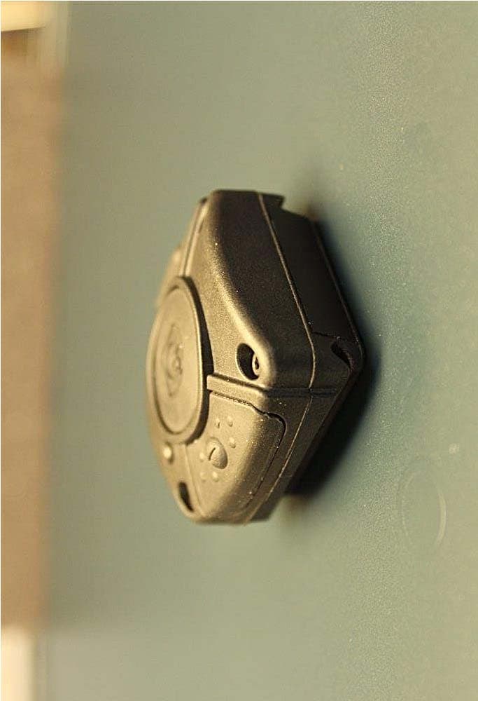
L52CTRT9011
Jun 02, 2015Wireless Control Command Transmitter
Equipment Class
DXX - Part 15 Low Power Communication Device Transmitter
L52CT-RXRCDM14
Oct 13, 2010CT-ClipCom digital
Equipment Class
CYY - Communications Receiver used w/Pt 15 Transmitter
L52CT-RXRCD9007
Oct 13, 2010CT-ClipCom digital SD
Equipment Class
CYY - Communications Receiver used w/Pt 15 Transmitter
L52CT-TXRT27
Oct 07, 2010Necklace Transmitter
Equipment Class
DXX - Part 15 Low Power Communication Device Transmitter