L52CT-TXRT27Necklace Transmitter
CeoTronics AG
Click to zoom
Application Details
- Equipment Class
- DXX - Part 15 Low Power Communication Device Transmitter
- Date of Grant
- Oct 07, 2010
- Application Purpose
- Original Equipment
- Date of Application
- Oct 07, 2010
- Equipment Note
- Necklace Transmitter
- Frequency Range
- 916.50000000 - 916.50000000
- Company
- CeoTronics AG
- Country
- Germany
Documents & Files
Document Text
Text extracted from the exhibit documents filed with the FCC. Open a document above to read the original.
Users Manual
Communication set In-Ear with ambient sound reception (CT-ClipCom Digital) Operation instructions 1 English 2 Content 1. Important safety instructions ........................................................................................................... 3 2. Description ...................................................................................................................................... 5 2.1 Ear-microphone ....................................................................................................................... 7 2.2 Earphone with gooseneck-microphone .................................................................................... 7 2.3 Universal three level ear plug ................................................................................................... 8 2.4 Individually ear mould .............................................................................................................. 8 2.5 PTT-button ............................................................................................................................. 12 2.6 CT-Wireless-PTT (example) .................................................................................................. 13 3. Commissioning and operation ....................................................................................................... 15 4. Safekeeping – storage .................................................................................................................. 16 5. Maintenance ................................................................................................................................. 16 5.1 Visual inspections .................................................................................................................. 16 5.2 Cleaning ................................................................................................................................ 16 5.3 Changing the protective cover of the gooseneck microphone ................................................ 17 6. Consumable parts + accessory ..................................................................................................... 17 3 1. Important safety instructions For the use of the device notice the national safety and accident prevention regulations and the following safety instructions shown in italics in this instruction manual. Before using CeoTronics products read completely the appropriate operating instructions. If in doubt, ask our technical staff. Use only CeoTronics products without damage and wear. If repair work of any kind needs to be done to CeoTronics products, arrange for it to be performed only by the company CeoTronics or by a specialized workshop that is authorized by CeoTronics. In all other cases our warranty and liability for the product shall lapse. Do not store CeoTronics products outside or in damp ambient conditions. At all times keep them clean, dry and at normal air humidity. CeoTronics products must not be stored in areas with a temperature of over +80° C (+176° F), e.g. in the summertime on the parcel shelf of a car. If not stated otherwise, the following temperature ranges are allowed for CeoTronics products: -10 to +55° C (+14 to +131° F) for operation, -40 to +80° C (-40 to +176° F) for storage. Do not immerse a CeoTronics product into water, if it is not expressly specified for this purpose. When using CeoTronics products that are equipped with connection leads ensure that the latter do not get caught up in operational machinery or wheels! CeoTronics products that are not intrinsically safe (explosion-proof) and therefore have no special explosion-proof designation must never be operated in potentially explosive environments (e.g. when refuelling cars, aircraft etc.). Devices that are not explosion-proof can unintentionally trigger off explosions in such areas! Connect CeoTronics accessories to a device or disconnect them from a device only when the device is switched off. In the case of intrinsically safe products (explosion-proof) this must always take place outside of the potentially explosive area. Otherwise the consequence could be an unintentional explosion! Please note that in some radios very loud signalling beeps could be present already in the moment of switching the radio on. There are various types of radios generating a series of signals in different loudness levels. It may be necessary to adjust the volume of the signalling beeps separately. These beeps could damage your hearing if they are set too high. Therefore, adjust signalling beeps to a convenient level as desired before starting to use CeoTronics accessories. Follow the instructions of the radio manufacturer’s operating manual to adjust the signalling beeps. For safety reasons reception volumes in excess of 85 dB (A) are possible with a whole series of CeoTronics products. However, these can be regulated by the user. After switching on the communication system, set the reception volume to approx. 1/2 the available loudness volume and then test the audible volume, e.g. by opening the squelch on the radio set. Do not set the volume any higher than is necessary. A very high volume setting can lead to damaged hearing, particularly if it is continuous. For high volumes or noise levels wear additional ear plugs. If in doubt, ask your safety officer or company doctor. Do not leave CeoTronics products lying around loose in cars, e.g. on the parcel shelf. Stow these products in a suitable, safe place in the car so that they do not present a danger to you or to other occupants of the car, if emergency braking is effected. Keep CeoTronics products out of the reach of children and any other persons who are not familiar with the handling and operation thereof. Packaging materials, e.g. filling materials and plastic bags are not toys and have to be kept out of the reach of children. There is a risk of children ingesting them and choking! …
Text truncated - open the document above for the full version.
External Photos
Title: Label Receiver Date: 14/09/2010 Page 3 of 3 Label Position (Backside of the Transmitter) Frontside of the Transmitter Label
ID Label/Location Info
Technical/Operationa Description And Block Diagramms Page 1 of 3 Transmitter Label Position Title: Label Receiver Date: 14/09/2010 Page 2 of 3 Label xx = examiner number dacb = Datecode ab = weeknumber cd = year Example = weeknum 12, year 2006 = 6102 Xxxxxx = WO-Number Title: Label Receiver Date: 14/09/2010 Page 3 of 3 Label Position (Backside of the Transmitter) Frontside of the Transmitter Label
Internal Photos
Technical/Operationa Description And Block Diagramms Page 1 of 2 Internal Photos Transmitter Title: Photos of Transmitter Date: 22/07/2010 Page 2 of 2 Top View Bottom View - + - + - +
Test Report
Note: The test data of this report is related only to the individual item which has been tested. This report shall not be reproduced except in full extent without the written approval of the testing laboratory. Test Report No. 69558-02103 (Edition 2) Page 1 of 41 Pages Prüfbericht / Test Report Nr. / No. 69558-02103 (Edition 2) Applicant: ELDAT GmbH Type of equipment: Necklace Transmitter Type designation: RT26/27/28 916,5 MHz FSK Order No.: 4500004046 Test standards: FCC Code of Federal Regulations, CFR 47, Part 15, Sections 15.205, 15.207, 15.215 and 15.249 Industry Canada Radio Standards Specifications RSS-Gen Issue 2, Section 7.2.2 and RSS-210 Issue 7, Sections 2.2, A2.9 (Category I Equipment) September 9, 2010 TÜV SÜD SENTON GmbH Äußere Frühlingstraße 45 94315 Straubing Germany Phone: +49 9421 5522-0 Fax: +49 9421 5522-99 Web: www.tuev-sued.com/senton eMail: [email protected] Test Report No. 69558-02103 (Edition 2) Page 2 of 41 Pages Table of Contents 1 Description of the Equipment Under Test (EUT) ............................................................ 3 2 Administrative Data ........................................................................................................ 4 3 Identification of the Test Laboratory ............................................................................... 5 4 Summary ........................................................................................................................ 6 5 Operation Mode and Configuration of EUT .................................................................... 7 6 Measurement Procedures .............................................................................................. 8 6.1 Bandwidth Measurements ....................................................................................... 8 6.2 Radiated Emission Measurement 9 kHz to 30 MHz ................................................. 9 6.3 Radiated Emission in Fully or Semi Anechoic Room ............................................. 11 6.4 Radiated Emission at Alternative Test Site ............................................................ 13 7 Photographs Taken During Testing .............................................................................. 15 8 Test Results ................................................................................................................. 22 8.1 Occupied Bandwidth .............................................................................................. 24 8.2 Bandwidth of the Emission..................................................................................... 28 8.3 Designation of Emissions ....................................................................................... 30 8.4 Restricted Bands of Operation ............................................................................... 31 8.5 Radiated Emission Measurement 9 kHz to 30 MHz .............................................. 33 8.6 Radiated Emission Measurement 30 MHz to 10 GHz ........................................... 34 8.7 Exposure of Humans to RF Fields ......................................................................... 36 9 Referenced Regulations ............................................................................................... 38 10 Revision History ........................................................................................................... 40 11 Charts taken during testing .......................................................................................... 41 TÜV SÜD SENTON GmbH Äußere Frühlingstraße 45 94315 Straubing Germany Phone: +49 9421 5522-0 Fax: +49 9421 5522-99 Web: www.tuev-sued.com/senton eMail: [email protected] Test Report No. 69558-02103 (Edition 2) Page 3 of 41 Pages 1 Description of the Equipment Under Test (EUT) General data of EUT Type designation 1 : RT26/27/28 916,5 MHz FSK Parts 2 : Serial number(s): DUT1 Manufacturer: ELDAT GmbH Type of equipment: Necklace Transmitter Version: As received FCC ID: Additional parts/accessories: Technical data of EUT Application frequency range: 902 MHz - 928 MHz Frequency range: 916.5 MHz Operating frequency: 916.5 MHz Type of modulation: FSK Pulse train: --- Pulse width: --- Number of RF-channels: 1 Channel spacing: --- Designation of emissions 3 : 196KF1D Type of antenna: Integrated on printed board Size/length of antenna: 8 cm Connection of antenna: detachable not detachable Type of power supply: Battery supply Specifications for power supply: nominal voltage: 3.0 V 1 Type designation of the system if EUT consists of more than one part. 2 Type designations of the parts of the system, if applicable. 3 Also known as "Class of Emission". TÜV SÜD SENTON GmbH Äußere Frühlingstraße 45 94315 Straubing Germany Phone: +49 9421 5522-0 Fax: +49 9421 5522-99 Web: www.tuev-sued.com/senton eMail: [email protected] Test Report No. 69558-02103 (Edition 2) Page 4 of 41 Pages 2 Administrative Data Application details Applicant (full address): ELDAT GmbH Im Gewerbepark 14 D-15711 Königs Wusterhausen Contact person: Mr. Andreas Eidam Order number: 4500004046 Receipt of EUT: May 26, 2010 Date(s) of test: May 31, 2010 Note(s): Report details Report number: 69558-02103 Edition: 2 Issue date: September 9, 2010 TÜV SÜD SENTON GmbH Äußere Frühlingstraße 45 94315 Straubing Germany Phone: +49 9421 5522-0 Fax: +49 9421 5522-99 Web: www.tuev-sued.com/senton eMail: [email protected] Test Report No. 69558-02103 (Edition 2) Page 5 of 41 Pages 3 Identification of the Test Laboratory Details of the Test Laboratory Company name: TÜV SÜD SENTON GmbH Address: Aeussere Fruehlingstrasse 45 D-94315 Straubing Germany Laboratory accreditation: DAR-Registration No. DAT-PL-171/94-03 Contact person: Mr. Johann Roidt Phone: +49 9421 5522-0 Fax: +49 9421 5522-99 TÜV SÜD SENTON GmbH Äußere Frühlingstraße 45 94315 Straubing Germany Phone: +49 9421 5522-0 Fax: +49 9421 5522-99 Web: www.tuev-sued.com/senton eMail: [email protected] Test Report No.…
Text truncated - open the document above for the full version.
Test Report
Test Equipment List with Calibration Data Page 1 of 2 Test report number(s):69558-02103 Date of test: 05/2010 Date of Calibration Type Inv.-No. Type Designation Serial Number Manufacturer Calibration Organization Last Next EMI test receiver 1028 ESHS10 860043/016 Rohde & Schwarz Rohde & Schwarz 02/2009 08/2010 EMI test receiver 1569 ESMI 839379/013 Rohde & Schwarz Rohde & Schwarz 10/2009 01/2012 EMI test receiver 1711 ESPI7 836914/0002 Rohde & Schwarz Rohde & Schwarz 09/2009 03/2011 EMI test receiver 1863 ESCI3 100008 Rohde & Schwarz Rohde & Schwarz 01/2010 07/2011 EMI test receiver 2010 ESPI7 101018 Rohde & Schwarz Rohde & Schwarz 11/2009 05/2011 EMI test receiver 2044 ESU8 100232 Rohde & Schwarz Rohde & Schwarz 05/2009 11/2010 Spectrum analyser 1666 FSP30 100063 Rohde & Schwarz Rohde & Schwarz 11/2009 05/2011 Preamplifier 1142 R14601 13120026 Advantest TÜV SÜD SENTON 11/2009 05/2011 Preamplifier 1484 ACO/180-3530 32641 CTT TÜV SÜD SENTON 03/2009 09/2010 Preamplifier 1651 CPA9231A 3393 Schaffner Electrotest TÜV SÜD SENTON 05/2008 11/2010 Preamplifier 1684 AFS3-00100800-32- LN 847743 MITEQ TÜV SÜD SENTON 05/2008 11/2010 V-network 1059 ESH3-Z5 894785/005 Rohde & Schwarz Rohde & Schwarz 05/2009 05/2012 V-network 1060 ESH3-Z5 862770/021 Rohde & Schwarz Rohde & Schwarz 04/2010 04/2013 V-network 1218 ESH3-Z5 830952/025 Rohde & Schwarz Rohde & Schwarz 07/2008 07/2011 Impedance stabization network (ISN) 2080 ISN T800 28597 Teseq 159 03/2010 06/2012 Loop antenna 1016 HFH2-Z2 882964/0001 Rohde & Schwarz Rohde & Schwarz 09/2009 03/2011 Double ridged waveguide horn antenna 1516 3115 9508-4553 EMCO Elektronik ARC 05/2008 05/2011 Note: Date of next calibration contains maximum tolerance if applicable. Test Equipment List with Calibration Data Page 1 of 2 Test report number(s):69558-02103 Date of test: 05/2010 Date of Calibration Type Inv.-No. Type Designation Serial Number Manufacturer Calibration Organization Last Next TRILOG antenna 2058 VULB 9163 9163-408 Schwarzbeck Schwarzbeck 11/2009 05/2011 TRILOG Broadband Antenna 1802 VULB 9163 9163-214 Schwarzbeck Schwarzbeck 11/2009 05/2011 Multimeter 1653 21 III 76530546 Fluke ZMK 05/2008 02/2011 Multimeter 1654 21 III 76381229 Fluke ZMK 03/2008 12/2010 Multimeter 1975 Fluke 77 III 92370108 Fluke ZMK 09/2008 06/2011 Multimeter 1976 Fluke 77 IV 93090238 Fluke ZMK 09/2008 06/2011 Digital multimeter 2025 Fluke 177 96720024 Fluke ZMK 09/2008 06/2011 Digital multimeter 2026 Fluke 177 96720025 Fluke ZMK 09/2008 06/2011 Horn antenna 1012 3160-05 9112-1001 EMCO Elektronik Note 2 Horn antenna 1013 3160-06 9112- 1001 EMCO Elektronik Note 2 Horn antenna 1014 3160-07 9112-1008 EMCO Elektronik Note 2 Note 1: Date of next calibration contains maximum tolerance if applicable. Note 2: According to manufacturer's specifications no calibration is required but mechanical check only. This check is performed before every test sequence.
Test Setup Photos
TÜV SÜD SENTON GmbH Äußere Frühlingstraße 45 94315 Straubing Germany Phone: +49 9421 5522-0 Fax: +49 9421 5522-99 Web: www.tuev-sued.com/senton eMail: [email protected] Test Report No. 69558-02103 (Edition 1) Page 16 of 41 Pages Test setup for radiated emission measurement 9 kHz – 30 MHz TÜV SÜD SENTON GmbH Äußere Frühlingstraße 45 94315 Straubing Germany Phone: +49 9421 5522-0 Fax: +49 9421 5522-99 Web: www.tuev-sued.com/senton eMail: [email protected] Test Report No. 69558-02103 (Edition 1) Page 17 of 41 Pages Test setup for radiated emission measurement (fully anechoic room) TÜV SÜD SENTON GmbH Äußere Frühlingstraße 45 94315 Straubing Germany Phone: +49 9421 5522-0 Fax: +49 9421 5522-99 Web: www.tuev-sued.com/senton eMail: [email protected] Test Report No. 69558-02103 (Edition 1) Page 18 of 41 Pages Test setup for radiated emission measurement (alternate test site) TÜV SÜD SENTON GmbH Äußere Frühlingstraße 45 94315 Straubing Germany Phone: +49 9421 5522-0 Fax: +49 9421 5522-99 Web: www.tuev-sued.com/senton eMail: [email protected] Test Report No. 69558-02103 (Edition 1) Page 19 of 41 Pages Test setup for radiated emission measurement (alternate test site) - continued - TÜV SÜD SENTON GmbH Äußere Frühlingstraße 45 94315 Straubing Germany Phone: +49 9421 5522-0 Fax: +49 9421 5522-99 Web: www.tuev-sued.com/senton eMail: [email protected] Test Report No. 69558-02103 (Edition 1) Page 20 of 41 Pages Test setup for radiated emission measurement (alternate test site) - continued - TÜV SÜD SENTON GmbH Äußere Frühlingstraße 45 94315 Straubing Germany Phone: +49 9421 5522-0 Fax: +49 9421 5522-99 Web: www.tuev-sued.com/senton eMail: [email protected] Test Report No. 69558-02103 (Edition 1) Page 21 of 41 Pages Test setup for radiated emission measurement (alternate test site) - continued -
Contact Information
Applicant
Thomas Guenther(CEO)
Test Firm
TUV SUD Product Service GmbH PS-EMC-STRRainer Heller
Technical Specifications
| # | Rule Parts | Frequency Range | Power Output |
|---|---|---|---|
| 1 | 15C | 916.5 MHz - 916.5 MHz | - |
Other Applications from CeoTronics AG

L52CT-M7CEO1
Jan 18, 2021CT-DECT M7 Module
Equipment Class
PUB - Part 15 Unlicensed PCS Base Station
L52-CTMUPTTBT
Nov 08, 2015CT-Multi-PTT Bluetooth
Equipment Class
CYY - Communications Receiver used w/Pt 15 Transmitter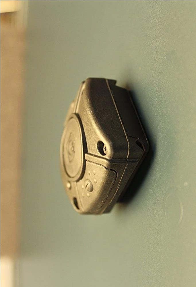
L52CTRT9011
Jun 02, 2015Wireless Control Command Transmitter
Equipment Class
DXX - Part 15 Low Power Communication Device Transmitter
L52CT-RXRCDM14
Oct 13, 2010CT-ClipCom digital
Equipment Class
CYY - Communications Receiver used w/Pt 15 Transmitter
L52CT-RXRCD9007
Oct 13, 2010CT-ClipCom digital SD
Equipment Class
CYY - Communications Receiver used w/Pt 15 Transmitter