L52CTRT9011Wireless Control Command Transmitter
CeoTronics AG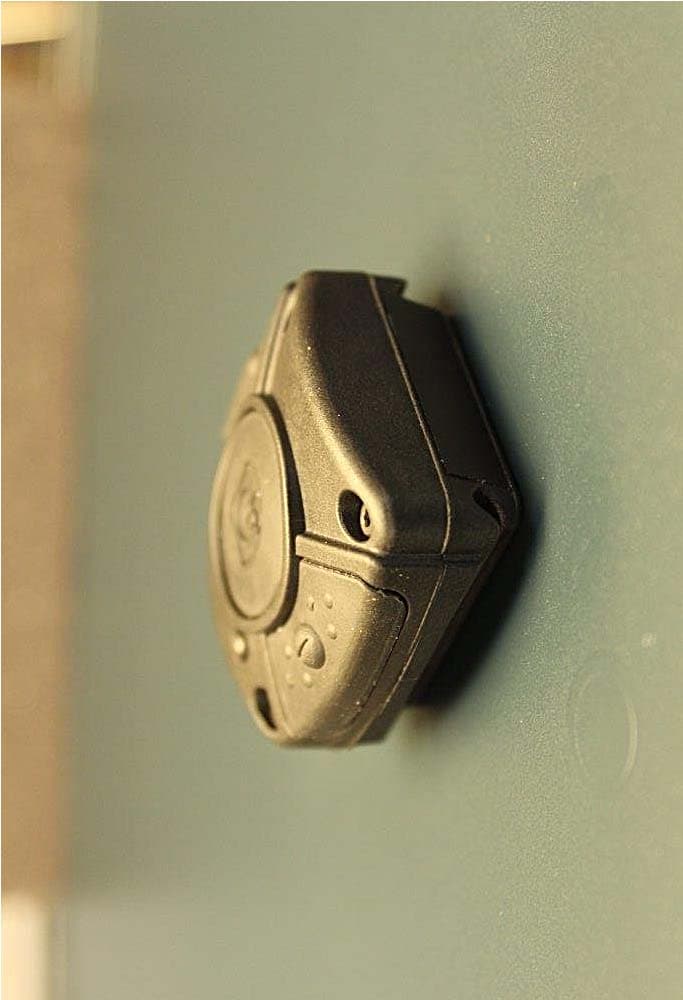
Click to zoom
Application Details
- Equipment Class
- DXX - Part 15 Low Power Communication Device Transmitter
- Date of Grant
- Jun 02, 2015
- Application Purpose
- Original Equipment
- Date of Application
- Jun 02, 2015
- Equipment Note
- Wireless Control Command Transmitter
- Frequency Range
- 916.50000000 - 916.50000000
- Company
- CeoTronics AG
- Country
- Germany
Documents & Files
Document Text
Text extracted from the exhibit documents filed with the FCC. Open a document above to read the original.
Users Manual
English - USA Revision: 01/1014 DOK 1652-us CT-WirelessPTT Operation Instructions For trouble-free operation of the receivers of the CT-WirelessPTT, make sure that the receiver housing is not in the immediate vicinity of the transmitting antenna of a radio or mobile phone. If the radio signal of the CT-WirelessPTT is overlaid by the comparatively strong transmission signal of a radio or mobile phone, this can impair the sensitivity of the CT-WirelessPTT in the near field of the transmitting antenna. This can interrupt radio transmission from the PTT transmitter to the PTT receiver! A CT-WirelessPTT is a PTT (Push to Talk) button/transmitter for activation or control of special CeoTronics products which you can covered keep in hand and use. Possible CeoTronics products are for example: CT-MultiPTT BT CT-MultiPTT 2C MIL CT-All-in-One Extreme CT-BluetoothAdapter CT-ClipCom Digital,- SD CT-MultiCom Wireless PTT In these products is a receiver for different CT-WirelessPTT installed. The CT-WirelessPTT must be paired with the receiver in the CeoTronics products. The pairing, deleting and some functions of the CT-WirelessPTT can be different at the different CeoTronics products. These procedures are described in the special user manuals of the CeoTronics products. Operation Range: approximately 5 m Frequency: 916,5 MHz Modulation: FSK CT-WirelessPTT MIL 4008007 / 916,5 MHz CT-WirelessPTT Standard 4008004 / 916,5 MHz Function by: MIL Standard CT-MultiPTT BT – operation instructions Dok 1643 Bluetooth button C1 C1 PTT C2 CT-MultiPTT 2C MIL – operation instructions Dok 1648 PTT – Primary radio circuit C1 C1 PTT – Secundary radio circuit C2 ASR – change of level C3 CT-All-in-One Extrem – operation instructions Dok 1639 Modus 1/2 Modus 3/4 PTT PTT C1 C1 Volume - NVK C2 Volume + Volume + C3 Volume - NVK C4 CT-BluetoothAdapter – operation instructions Dok 1344 Bluetooth button C1 C1 CT-ClipCom Digital SD – operation instructions Dok 1288 PTT C1 C1 CT-MultiCom Wireless PTT – operation instructions Dok 1644 PTT C1 C1 C1 C1 oder C2 C4 C3 Revision: 01/1014 DOK 1652-us Warning - and Safety instructions Notice for the use of the device for prevention of personal injury or property damage the national safety and accident prevention regulations and the following warning and safety instructions in this instruction manual. Important Notes for operation of the Transmitter in the USA and Canada Changes or modifications not expressly approved by the party responsible for compliance could void the user's authority to operate the equipment This device complies with Part 15 of the FCC Rules and Industry Canada licence-exempt RSS standard(s). Operation is subject to the following two conditions: (1) this device may not cause harmful interference, and (2) this device must accept any interference received, including interference that may cause undesired operation. Le présent appareil est conforme aux CNR d'Industrie Canada applicables aux appareils radio exempts de licence. L'exploitation est autorisée aux deux conditions suivantes : (1) l'appareil ne doit pas produire de brouillage, et (2) l'appareil doit accepter tout brouillage radioélectrique subi, même si le brouillage est susceptible d'en compromettre le fonctionnement. General safety instructions Before using CeoTronics products read completely the appropriate operating instructions. If in doubt, ask our technical staff. Keep these operating instructions for later use. If repair work of any kind needs to be done to CeoTronics products, arrange for it to be performed only by the company CeoTronics or by a specialized workshop that is authorized by CeoTronics. In all other cases our warranty and liability for the product shall lapse. Keep CeoTronics products out of the reach of children and any other persons who are not familiar with the handling and operation thereof. CeoTronics products may only be used for the specific application envisaged. Product damage! Do not immerse a CeoTronics product into water, if it is not expressly specified for this purpose. Impairment of flight operation! When on board an airplane always keep a transmitter/receiver switched off. Operation of the transmitter/receiver could affect the safety of the airplane and it is therefore prohibited. Never operate electronic devices on board an airplane without the express approval of an authorized member of the cabin crew. Impairment of radio transmission! Transmit only when it is necessary. Unnecessarily occupying a channel can prevent the transmission of vitally important information. Risk of explosion! CeoTronics products that are not intrinsically safe (explosion-proof) and therefore have no special explosion-proof designation must never be operated in potentially explosive environments (e.g. when refuelling cars, aircraft etc.). Devices that are not explosion-proof can unintentionally trigger off explosions in such areas! Adverse effect on cardiac pacemakers If you are a cardiac pacemaker carrier, before operating a transmitter/receiver ask the manufacturer of your cardiac pacemaker for information about any impairment that might be caused due to high frequencies. Revision: 01/1014 DOK 1652-us Receipt of goods Inspect the goods immediately upon receipt for completeness and possible transport damages! Notify transport damages immediately to the forwarder and CeoTronics AG! Transport and storage Make sure the environmental conditions specified in the technical data sheet are met and complied with in transit, at the storage location and site of operation! Take appropriate measures to avoid vibration, impacts and drops! Choose adecuate packaging when dispatching the device. Store the device after cleaning it in an appropriate dry place at constant ambient conditions. Avoid extreme temperature fluctuation! Safe disposal of packaging material Danger of ingestion and choking! Packaging materials, e.g. filling materials and plastic bags are not toys and have to be kept out of the reach of ch…
Text truncated - open the document above for the full version.
Cover Letter(s)
Ersteller: D. Brandhorst Revision: 00 Erstelldatum: 02.01.2012 Datum: 00.00.0000 Seite 1 von 1 Long/Short-term Confidentiality Request PHOENIX TESTLAB GmbH Date: 22 October 2014 Product Certification Königswinkel 10 D 32825 Blomberg FCC ID: L52CTRT9011 To Whom it may concerns, Pursuant to sections 0.457(d) and 0.459 of CFR 47 and to avoid premature release of sensitive information prior to marketing or release of the product to the public, we hereby requests long-term confidential treatment of information accompanying this application as outlined below: Schematics Parts List Block Diagram Tune-Up Info Operational Description In addition we hereby request the following exhibits contained in this application to be temporarily (short-term confidentilality) withheld from the public disclosure for an initial period of days until: not applicable External Photos Test Setup Photos Internal Photos Users Manual The above materials contain trade secrets and proprietary information not customarily released to the public. The public disclosure of these matters might be harmful to the applicant and provide unjustified benefits to its competitors. The applicant understands that pursuant to rule 0.457(d), disclosure of this application and all accompanying documentation will not be made before the date of the GRANT for this application. Signatory B. Sc. Uwe DOLLITZ Graduated Certification Specialist PHOENIX TESTLAB GmbH
Test Report
Test Report No.: G0M-1401-3559-TFC249DT-V03 Eurofins Product Service GmbH Storkower Str. 38c, D-15526 Reichenwalde, Germany Page 1 of 35 FCC TEST REPORT FCC 47 CFR Part 15C Industry Canada RSS-210 Intentional radiator operating within the 902 – 928 MHz band Report Reference No. ..................... : G0M-1401-3559-TFC249DT-V03 Testing Laboratory ......................... : Eurofins Product Service GmbH Address ............................................. : Storkower Str. 38c 15526 Reichenwalde Germany Accreditation ..................................... : A2LA Accredited Testing Laboratory, Certificate No.: 1983.01 FCC Filed Test Laboratory, Reg.-No.: 96970 IC OATS Filing assigned code: 3470A Applicant’s name ............................ : ELDAT GmbH Address ............................................. : Im Gewerbepark 14 15711 Königs Wusterhausen GERMANY Test specification: Standard ........................................... : 47 CFR Part 15C RSS-210, Issue 8 Amendment 1, 2015-02 RSS-Gen, Issue 4, 2014-11 ANSI C63.4:2009 ANSI C63.10:2009 Equipment under test (EUT): Product description Funksender Model No. RT9011 Additional Model(s) None Brand Name(s) None Hardware version 105725 V01 Firmware / Software version Prüf-Software Test result Passed Test Report No.: G0M-1401-3559-TFC249DT-V03 Eurofins Product Service GmbH Storkower Str. 38c, D-15526 Reichenwalde, Germany Page 3 of 35 Version History Version Issue Date Remarks Revised by 01 2014-03-24 Initial Release 02 2014-12-15 Replaced document: G0M-1401-3559-TFC249DT-V01 Replaced by: G0M-1401-3559-TFC249DT-V02 Changes : - Assigned frequency band corrected - Operating frequency range corrected - Test date corrected. - Test equipment corrected - 20 dB bandwidth added - Version of test software corrected C. Weber 03 2015-04-27 Replaced document: G0M-1401-3559-TFC249DT-V02 Replaced by: G0M-1401-3559-TFC249DT-V03 Changes : - IC RSS Standards updated C. Weber Test Report No.: G0M-1401-3559-TFC249DT-V03 Eurofins Product Service GmbH Storkower Str. 38c, D-15526 Reichenwalde, Germany Page 4 of 35 REPORT INDEX 1 EQUIPMENT (TEST ITEM) DESCRIPTION 5 1.1 Photos – Equipment External 6 1.2 Photos – Equipment internal 8 1.3 Photos – Test setup 9 1.4 Supporting Equipment Used During Testing 10 1.5 Test Modes 11 1.6 Test Equipment Used During Testing 12 1.7 Sample emission level calculation 13 2 RESULT SUMMARY 14 3 TEST CONDITIONS AND RESULTS 15 3.1 Test Conditions and Results – Occupied Bandwidth 15 3.2 Test Conditions and Results – 20 dB Bandwidth 17 3.3 Test Conditions and Results – Fundamental field strength emissions 18 3.4 Test Conditions and Results – Emissions radiated outside the specified frequency band 20 ANNEX A Fundamental field strength emissions 22 ANNEX B Transmitter radiated spurious emissions 24 Test Report No.: G0M-1401-3559-TFC249DT-V03 Eurofins Product Service GmbH Storkower Str. 38c, D-15526 Reichenwalde, Germany Page 5 of 35 1 Equipment (Test item) Description Description Funksender Model RT9011 Additional Model(s) None Brand Name(s) None Serial number None Hardware version 105725 V01 Software / Firmware version Prüf-Software Equipment type End product Radio type Transmitter only Radio technology custom Operating frequency range 916.5 MHz Assigned frequency band 902 - 928 MHz Frequency range F MID 916.5 MHz Spreading None Modulations FSK Number of channels 1 Channel spacing None Number of antennas 1 Antenna Type integrated Model PCB antenna Manufacturer ELDAT Gain unspecified Manufacturer ELDAT GmbH Im Gewerbepark 14 15711 Königs Wusterhausen GERMANY Power supply V NOM 3.0 VDC (battery) V MIN N/A V MIN N/A AC/DC-Adaptor Model N/A Vendor N/A Input N/A Output N/A Test Report No.: G0M-1401-3559-TFC249DT-V03 Eurofins Product Service GmbH Storkower Str. 38c, D-15526 Reichenwalde, Germany Page 6 of 35 1.1 Photos – Equipment External EUT TOP EUT BOTTOM Test Report No.: G0M-1401-3559-TFC249DT-V03 Eurofins Product Service GmbH Storkower Str. 38c, D-15526 Reichenwalde, Germany Page 7 of 35 EUT OPEN Test Report No.: G0M-1401-3559-TFC249DT-V03 Eurofins Product Service GmbH Storkower Str. 38c, D-15526 Reichenwalde, Germany Page 8 of 35 1.2 Photos – Equipment internal PCB TOP PCB BOTTOM Test Report No.: G0M-1401-3559-TFC249DT-V03 Eurofins Product Service GmbH Storkower Str. 38c, D-15526 Reichenwalde, Germany Page 9 of 35 1.3 Photos – Test setup TEST SETUP Test Report No.: G0M-1401-3559-TFC249DT-V03 Eurofins Product Service GmbH Storkower Str. 38c, D-15526 Reichenwalde, Germany Page 10 of 35 1.4 Supporting Equipment Used During Testing Product Type* Device Manufacturer Model No. Comments None *Note: Use the following abbreviations: AE : Auxiliary/Associated Equipment, or SIM : Simulator (Not Subjected to Test) CABL : Connecting cables Test Report No.: G0M-1401-3559-TFC249DT-V03 Eurofins Product Service GmbH Storkower Str. 38c, D-15526 Reichenwalde, Germany Page 11 of 35 1.5 Test Modes Mode # Description Single General conditions: EUT powered by fully battery Radio conditions: Mode = standalone transmit Spreading = None Modulation = FSK Duty cycle = 100 % Cond. rated power level = 8.5 dBm (firmware setting) Test Report No.: G0M-1401-3559-TFC249DT-V03 Eurofins Product Service GmbH Storkower Str. 38c, D-15526 Reichenwalde, Germany Page 12 of 35 1.6 Test Equipment Used During Testing Measurement Software Description Manufacturer Name Version EMC Test Software Dare Instruments Radimation 2014.1.15 Occupied Bandwidth Description Manufacturer Model Identifier Cal. Date Cal. Due Spectrum Analyzer R&S FSP 30 EF00312 2014-02 2015-02 20 dB Bandwidth Description Manufacturer Model Identifier Cal. Date Cal. Due Spectrum Analyzer R&S FSP 30 EF00312 2014-02 2015-02 Field strength emissions Description Manufacturer Model Identifier Cal. Date Cal. Due Semi-anechoic chamber Frankonia AC 1 EF00062 - - Spectrum Analyzer R&S FSIQ26 EF00242 2013-06 2014-06 Biconical Antenna R&S HK 116 EF00012 2013-02 2016-02 LPD Antenna R&S HL 223 EF00187 2011-02 2014-02 LPD Antenna R…
Text truncated - open the document above for the full version.
Contact Information
Applicant
Thomas Guenther(CEO)
Test Firm
Eurofins Product Service GmbHRobert Kschiwan-Kaspar
Technical Specifications
| # | Rule Parts | Frequency Range | Power Output |
|---|---|---|---|
| 1 | 15C | 916.5 MHz - 916.5 MHz | - |
Other Applications from CeoTronics AG

L52CT-M7CEO1
Jan 18, 2021CT-DECT M7 Module
Equipment Class
PUB - Part 15 Unlicensed PCS Base Station
L52-CTMUPTTBT
Nov 08, 2015CT-Multi-PTT Bluetooth
Equipment Class
CYY - Communications Receiver used w/Pt 15 Transmitter
L52CT-RXRCDM14
Oct 13, 2010CT-ClipCom digital
Equipment Class
CYY - Communications Receiver used w/Pt 15 Transmitter
L52CT-RXRCD9007
Oct 13, 2010CT-ClipCom digital SD
Equipment Class
CYY - Communications Receiver used w/Pt 15 Transmitter
L52CT-TXRT27
Oct 07, 2010Necklace Transmitter
Equipment Class
DXX - Part 15 Low Power Communication Device Transmitter