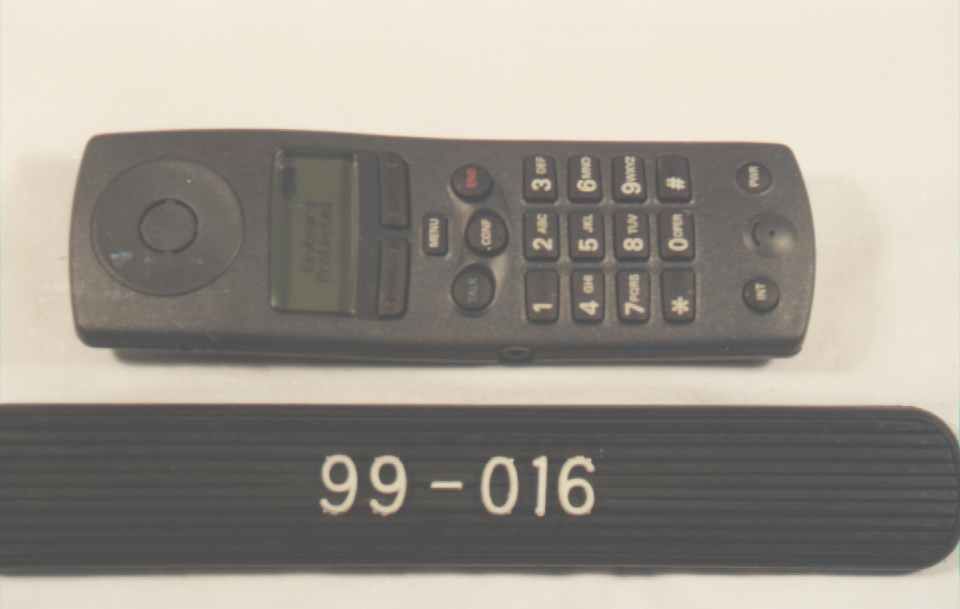
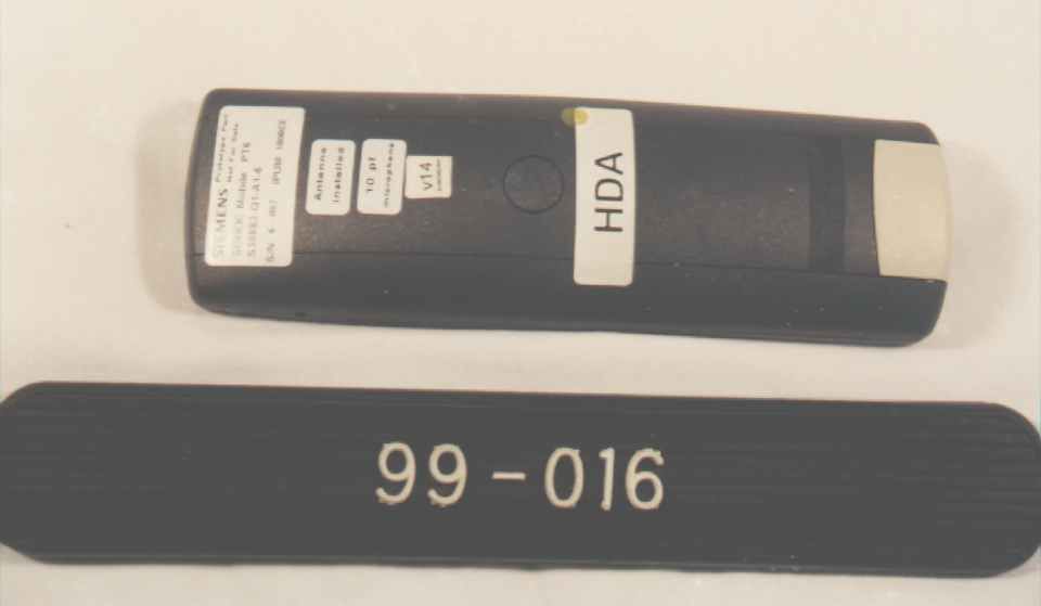
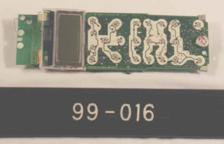
L82-228869Cordless Telephone Handset
Siemens Information and Communication Mobile LLC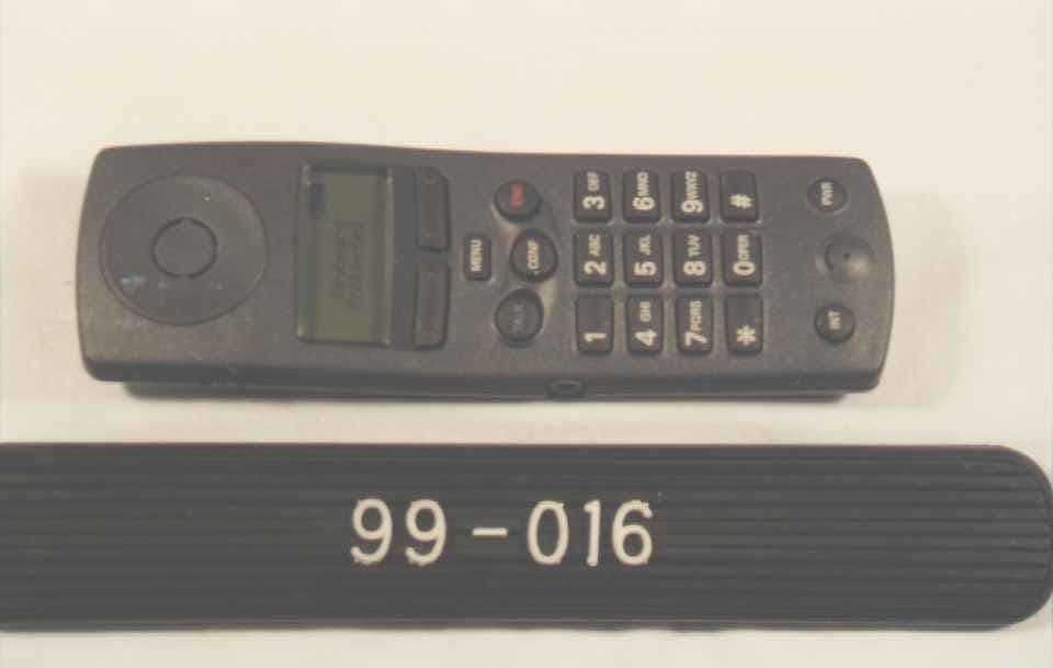
Click to zoom
Application Details
- Equipment Class
- DSS - Part 15 Spread Spectrum Transmitter
- Date of Grant
- Sep 30, 1998
- Application Purpose
- Original Equipment
- Date of Application
- Jul 26, 1998
- Equipment Note
- Cordless Telephone Handset
- Frequency Range
- 2401.05000000 - 2482.27000000
- Country
- United States
Documents & Files
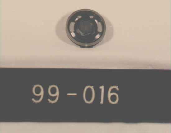
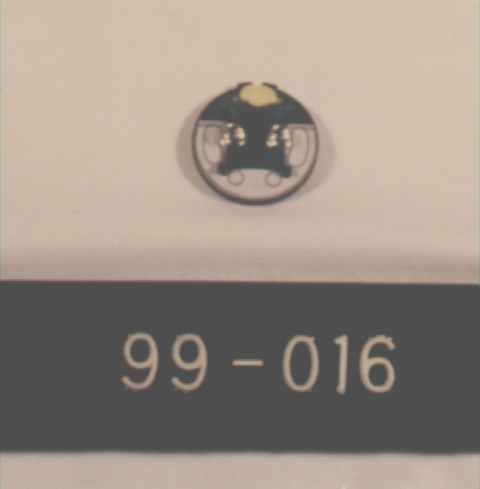
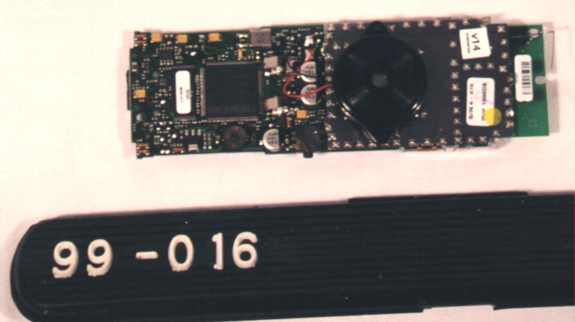
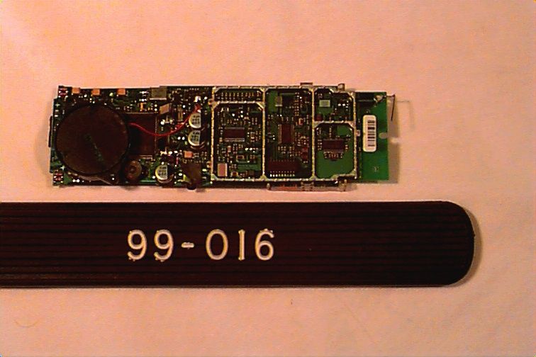
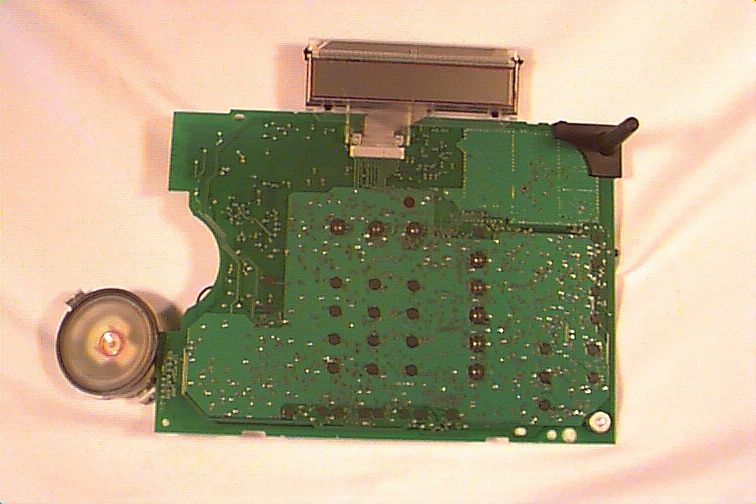
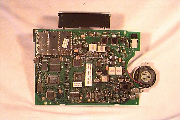
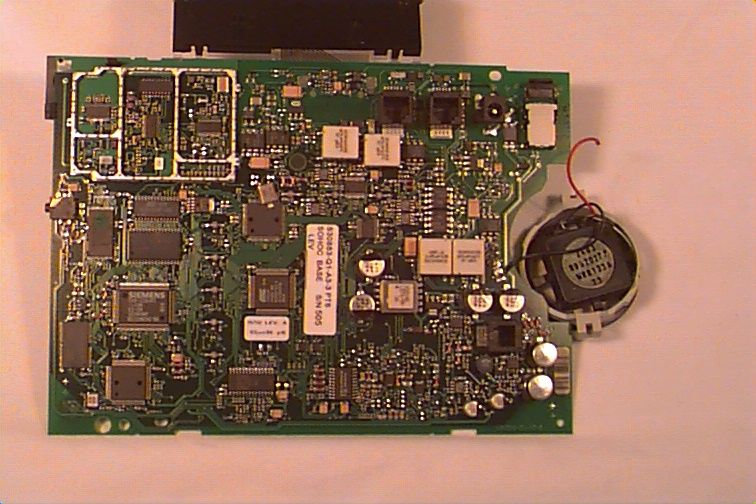
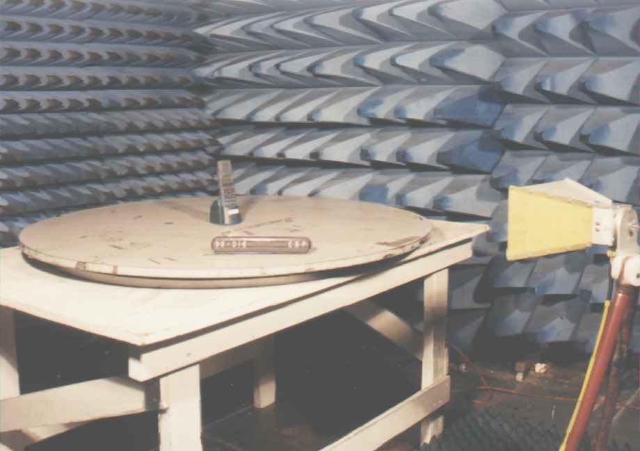
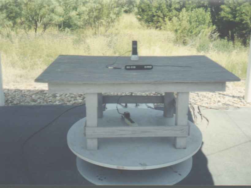
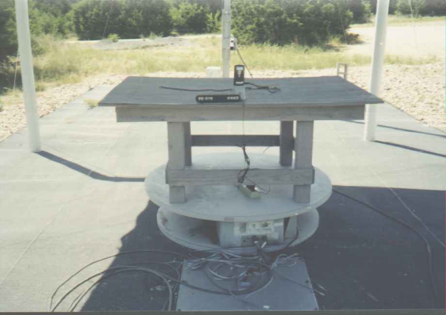
Document Text
Text extracted from the exhibit documents filed with the FCC. Open a document above to read the original.
Users Manual
Siemens Wireless Terminals July 1998 Siemens is a registered trademark of Siemens AC. Siemens Wireless Terminals is a division of Siemens Business Communication Systems Inc. RBRC is a trademark of the Rechargeable Battery Recycling Corporation. Information subject to change since Siemens reserves the right, without notice, to make changes in equipment design or components as progress in engineering or manufacturing methods warrant. Order Number: PB242010 Part Number: A30883-N1-A1-1 Siemens l998 ALL RIGHTS RESERVED Table of Contents IMPORTANT SAFETY INSTRUCTIONS AND PRODUCT INFORMATIONV 1. INSTALLATION1 CONTENTS OF SYSTEM BOX1 STEPS FOR INSTALLATION2 QUICK START7 HOW TO REACH US11 2. THE BASICS13 GENERAL INFORMATION14 DESK STATION16 CORDLESS HANDSET22 3. MAKING, ANSWERING, AND TERMINATING CALLS 27 MAKING CALLS27 ANSWERING CALLS22 TERMINATING CALLS35 4. MANAGING CALLS37 HOLD37 TRANSFER29 CONFERENCE39 CALL BARGE IN41 5. DIRECTORY AND CALL LOG43 DIRECTORY43 CALL LOG54 6. ANSWERING SYSTEM63 GETTNG STARTED63 USING THE ANSWERING SYSTEM FROM THE DESK STATION64 USING THE ANSWERING SYSTEM FROM THE CORDLESS HANDSET OF AN EXTERNAL LINE71 7. CUSTOMIZING YOUR SYSTEM73 DESK STATOINS VOLUME KEY MENUS73 DESK STATIONS MAI N MENU74 SYSTEN SETTINGS77 CALLER ID CALL LOG84 CORDLESS HANDSET'S MAIN MENU 86 LOAD SETTINGS .91 APPENDIX A - MENU TREES95 DESK STAT ON DREC~ORY MEN TREE95 DESK STATON MENU KEY MENU TREE96 CORDLESS HANDSET MENJ KEY MENU TREE180 ANSWERING SYS~EM MENU TREE182 APPENDIX B- TROUBLESHOOTING105 PROBLEMS WITH THE GIGASET 2420 DESK STATION105 PROBLEMS WITH THE GIGASE- 2420 CORDLESS HANOSE- .108 APPENDIX C - PROGRAMMING WORKSHEETS111 DESK STATION SETTINGS111 ANSWERING SYSTEM SETTINGS113 CORDLESS HANDSET SETTINGS114 INDEX115 Important Safety Instructions and Product Information BEFORE USING YOUR TELEPHONE EQUIPMENT, BASIC SAFETY INSTRUCTIONS SHOULD ALWAYS BE FOLLOWED TO REDUCE THE RISK OF FIRE, ELECTRIC SHOCK AND INJURY TO PERSONS AND DAMAGE TO PROPERTY. 1.Read and understand all instructions. 2.Follow all warnings and instructions including those marked on the product. 3.Unplug this product from the wall telephone jack and power outlet before cleaning. Do not use liquid cleaners or aerosol cleaners. Use damp cloth for cleaning. 4.Do not use the desk station near water, for example, near a bathtub, wash bowl, kitchen sink, or laundry tub, in a wet basement or near a swimming pool. B.Do not place this product on an unstable cart, stand or table. The product may fall, causing serious damage to the product. 6.Slots or openings in the cabinet and the back and bottom are provided for ventilation, to protect it from overheating. These openings must not be blocked or covered. The openings should never be blocked by placing the product on a bed, or other similar surface. This product should never be placed near or over a radiator or heat register. This product should not be placed in a built-in installation unless proper ventilation is provided. Safety Instructions and Product Information 7.This product should be operated only from the type of power source indicated on the marking label. If you are not sure of the type of power supply to your home, consult your dealer or local power company. 8.Do not overload wall outlets and extension cords as this can result in the risk of fire or electric shock. 9.Never push objects of any kind into this product through cabinet slots as they may touch dangerous voltage points or short out parts that could result in the risk of fire or electric shock. Never spill liquid of any kind on this product. 10.To reduce the risk of electric shock or burns, do not disassemble this product, but take it to qualified service personnel when some service or repair work is required. Opening or removing covers may expose you to dangerous voltages, dangerous electrical current or other risks. Incorrect reassembly can cause electric shock when the appliance is subsequently used. 11.Unplug the desk station from the wall outlet and refer servicing to qualified service personnel under the following conditions: a.If liquid has been spilled into the product. b.If the product has been exposed to rain or water. a.If the product does not operate normally by following the operating instructions. Adjust only those controls that are covered by the operating instructions because improper adjustment of other controls may result in damage and will often require extensive work by qualified service personnel to restore the product to normal operation. d.If the product has been dropped or cabinet has been damaged. e.If the product exhibits a distinct change in performance. 1 2. Avoid using telephone during an electrical storm. There may a remote risk of electrical shock from lightning. 13.Do not use the telephone to report a gas leak in the vicinity of the leak. 14.The antenna on the base of this telephone does not retract. To prevent injury, do not place the telephone where persons can step, trip or fall on the telephone. 15.Do not place metal objects on the antenna. Battery Safety Precautions: To reduce the risk of fire, injury or electric shock, or property damage, and to properly dispose of batteries, please read and understand the following instructions. CONTAINS NICKEL CADMIUM BATTERY. BATTERY NICAD MUST BE RECYCLED OR DISPOSED OF PROPERLY. DO NOT DISPOSE OF IN MUNICIPAL WASTE. 1Only use type AA Nickel-Cadmium (Ni-Cd) or type AA Nickel-Metal Hydride (NiMH) rechargeable batteries in the cordless handset and reserve battery compartment. DO NOT use other rechargeable batteries or non-rechargeable batteries. The batteries could short-circuit, and the battery shell may be damaged causing a hazardous condition. Instruction labels are located in the handset and charging unit battery compartment. 2.Always follow basic safety precautions when using and disposing of batteries. Do not dispose of the batteries in a fire; the cells may explode. Do not expose batteries to water. Check with local codes for spe…
Text truncated - open the document above for the full version.
Block Diagram
Block Diagram for Gigaset 2420HS RF Receiver RF Transmitter 2.4 GHz 256K Mask ROM 4K EEPROM 5X5 Key Matrix 35x97 pixels (3) Speaker Microphone Tone Ringer BMC Processor Add (18 bits), Data (8 Bits) (2) I 2 C (10) Display (4) (6) DSP Analog Front End Power Supply Control (2)A/DRSSI, Batt Battery Charging Contacts Power Supply Charge Control Battery (2 Cells) +5V V.24 Ext. Mic I/F Headset Conn (1) Audio I/F Not Used Test Point 5k RAM
Cover Letter(s)
Federal Communication Commission Equipment Authorization Division, Application Processing Branch 7435 Oakland Mills Road Columbia, MD 21048 TO WHOM IT MAY CONCERN Siemens Business Communications authorizes Professional Testing (EMI) Inc., to operate on its behalf for application filing with the FCC on the following products: FCC ID NumberProduct Title/Model L82-228869CCS2420 Mobile Handset Unit L82-228870CCS2420 Base Unit If you have any questions, please feel free to contact me at the address shown below. Sincerely, SIEMENS BUSINESS COMMUNICATIONS Edwin L. Bronaugh Edwin L. Bronaugh, Sr. Eng. Lead, Hardware Design Assurance 2205 Grand Avenue Parkway Austin, TX 78728-3811 email: [email protected] Fax:512-990-6335
Operational Description
FCC ID L82-228870 PRODUCT AND OPERATIONAL DESCRIPTION: SIEMENS GIGASET 2420 DESK STATION 1.0 General Description The Siemens Gigaset 2420 Desk Station is the base unit of the Siemens Gigaset 2420 Small Office/Home Office (SOHO) phone system. This system is comprised of one base station per system and up to eight (8) wireless handsets. The Desk Station is powered by an AC to DC conversion module and has an interface for connection to the public telephone utility. Communication can be made between the handsets, between the Handsets and the Desk Station, and between system components and telephone utility. All communications for the Gigaset 2420 System are routed through the Desk Station (even for handset to handset communication). 2.0 Wireless Description Wireless communications for the Gigaset 2400 SOHO System are accomplished using a low power frequency hopping spread spectrum technique. This link is compliant with Part 15.247 of the Rules. The spread spectrum link operates over 96 channels in the 2400 MHz band. The typical output power of the unit is 0.25 watts with an individual channel bandwidth of 700 kHz at 3 dB down and 850 kHz at 20 dB down. Hopping of the frequency over this band is based on a pseudo-random code coordinated between the handsets and the base unit. Handsets establish coordination with the base unit during the power-on cycle. This process prevents inadvertant connection of other Gigaset 2400 Handsets to a specific network that they are not intended to operate with.
Test Report
FCC ID# L82-228869 FCC ID: L82-228869 Prepared for: SIEMENS BUSINESS COMMUNICATIONS 2205 Grand Avenue Austin, Texas 78728-3811 By: Professional Testing (EMI), Inc. 1601 FM 1460, Suite B Round Rock, Texas 78664 Submitted to: Federal Communications Commission Equipment Authorization Division, Application Processing Branch 7435 Oakland Mills Road Columbia, MD 21048 August 1998 FCC Type Certification Test Report of an Intentional Radiator SIEMENS BUSINESS COMMUNICATION SYSTEMS GigaSet 2400HS Spread Spectrum Cordless Phone System Handset (Transmitter Portion) FCC ID# L82-228869 Professional Testing (EMI) Inc. 2 of 25 Table of Contents Title Page ..............................................................................................................................................1 Table of Contents...................................................................................................................................2 Certificate of Compliance......................................................................................................................4 Appendices...........................................................................................................................................2 1.0Equipment Under Test (EUT) Description..................................................................................4 1.1Equipment Under Test (EUT) Operation.....................................................................................5 2.0Occupied Bandwidth Measurements...........................................................................................5 2.1Test Procedure..............................................................................................................................5 2.2Test Criteria..................................................................................................................................5 2.3Test Results...................................................................................................................................6 3.0Hop Frequency Quantity..............................................................................................................6 3.1Evaluation Procedure....................................................................................................................6 3.2Evaluation Criteria........................................................................................................................6 3.3Evaluation Results........................................................................................................................6 4.0Average Time of Occupancy........................................................................................................7 4.1Test Procedure..............................................................................................................................7 4.2Test Criteria..................................................................................................................................7 4.3Test Results...................................................................................................................................7 5.0Peak Output Power.......................................................................................................................7 5.1Measurement Procedure...............................................................................................................7 5.2Evaluation Criteria........................................................................................................................8 5.3Evaluation Results........................................................................................................................8 6.0Out-of-Band Emission Measurements.........................................................................................8 6.1Test Procedure..............................................................................................................................8 6.2Test Criteria..................................................................................................................................8 6.3Test Results...................................................................................................................................9 7.0Frequency Stability Analysis........................................................................................................9 7.1Evaluation Procedure....................................................................................................................9 7.2Evaluation Results........................................................................................................................9 8.0Antenna Requirement...................................................................................................................9 8.1Evaluation Procedure....................................................................................................................9 8.2Evaluation Criteria......................................................................................................................10 8.3Test Results.................................................................................................................................10 9.0List of Test Equipment...............................................................................................................10 Appendices Appendix A: Occupied BandwidthTest Data.....................................................................................12 Appendix B: Hop Frequency Quantity Evaluation Data....................................................................16 Appendix C: Average Time of Occupancy Test Data........................................................................19 Appendix D: Peak Output Power Test Data.......................................................................................22 Appendix E: Out of Band Emiss…
Text truncated - open the document above for the full version.
Test Report
1 FCC APPLICATION INQUIRY RESPONSE L82-228869: SIEMENS GIGASET 2400 HANDSET Correspondence Number: 3531 September 22, 1998 1.0 Overview This package was compiled to reply to inquiries made by Mr. Rich Fabina of the FCC regarding the Type Certification Application for the Siemens Gigaset 2400 Handset. Each Inquiry item is listed below followed by the response. 2.0 Inquiry Responses (1) Provide radiated emission test data on two more channels as required by Section 15.31(m) of the FCC rules. This section requires test data on three chnnels, high middle and low when the transmitter operates over a frequency range greater than 10 MHz. Test data for only one channel (high channel) was provided. Answer: Additional tests were performed on September 22, 1998 and are included with this report. Comparison of the spurious emissions to Section 15.205 has also been made as part of this process. (2) Address the RF safety of this transmitter as required by Section (15.247(b)(4) of the Rules. See Supplement C to OET Bulletin 65 or call Mr. Kwok Chan for guidance. Please talk to Mr. Chan regarding SAR data which may be needed for this transmitter. Answer: Based on a conversation with Kwok Chan of the Commission on September 16, 1998, the following RF Safety analysis is provided: The power used for evaluation to the RF Safety Hazard Specification can be derated based on the percentage that the transmit signal is actually present over time. For the Gigaset 2400 Desk Station, the duty cycle of the transmit signal over time is 1/8. The Power level used for comparison to the OET-65C limit can be calculated as follows: Ref. Power = (Peak Power) * (Duty Cycle) = (0..373 watts) * ( 1/8) = 0.0466 watts This figure is below the threshold (<0.2 watts at 2450 MHz for cordless phone handsets and most other trasnmitters using monopole or dipole type antennas as an integral part of the 2 device) for this device. The Gigaset 2400 Handset uses an internal monopole antenna. Based on this criteria, special warnings or instructions are not required to show compliance for this device. (3) The measured output power from this transmitter (469 milliwatts ERP) does not match the maximum output power (372 milliwatts) requested on the application (731) form. Please address this discrepancy. Answer: An error was made during the filing of the application. The highest ERP of the device was 372 (retested as 373 mW yesterday). We request that the 731 be corrected to accurately reflect this test data. (4) Provide a signed and dated letter on company letterhead paper that specifies what sections of the application require confidentiality because they are trade secret information. Trade secret information is typically information that involves considerable expense in research and development for the applicant. User’s Manuals and photos of the equipment are not considered trade secret information without documented, special considerations. Answer: Following an additional review of this application, the only portion of this application that should be confidential are the schematics. All other items should be not confidential. (5) Provide a list of the hop sequences and their channel frequencies used by this transmitter to show that its algorithm is pseudo-random in nature, not in equal increments. Where does the hop commence when the previous hop sequence is not completed? Answer: The full frequency listing is provided in the original test report. The Pseudo Random Hopping Sequence is derived from the Base station unique identity. It is done by taking the Base ID number and modulo it with 16. The result “B_ID” is a number from 0 to 15. 2 variables are implemented which are Subset_Counter and Index_Counter. • Subset_Counter repeats a sequence of 0,2,4,6,8,10,12,11,9,7,5,3,1,0,.. • Index_Counter repeats a sequence of 0,1,2,3,4,5,6,7,0,... 3 Depending on B_ID and Subset_Counter a Sequence_Number (a number from 1 to 12) is derived: 123456789101112 0123456789101112 1234567891011121 2345678910111212 3456789101112123 4567891011121234 5678910111212345 6789101112123456 7891011121234567 8910111212345678 9101112123456789 10111212345678910 1112123456789811 12121110987654321 13111098765432112 14109876543211211 15987654321121110 Given a sequence number and Index_Counter an offset is derived. 123456789101112 0135315486468 1246426375357 2311753642886 3422864531775 4573177228624 5684288117513 6757531864242 7868642753131 Then : Channel = (Subset_Counter) x 8 + Offset So the following are samples of sequences Base ID 1: 102026324451636975859594847468625045332721111281630364253596579879392867864 585243373117934141824384649577177819190807670564847392519155612222834... B_ID Index Counter Subset Counter Sequence Number Sequence Number Offset value 4 Base ID 2: 121824364355616777878889867666605442372519133082228344551577179859091847870 565044352923916101630384149636973839293827268624840393117117414202632... Base ID 3: 1016283547535969798090918178685852463429171150142026374349637177828889837670 62484236272115128223033415561657584949585746460544032312393612182439... The phone hops after each 10 ms frame, not during a frame. The base transmitter is on continuously, with or without voice data, thus the phone transmits frequencies as the pseudo random sequence dictates. Sequential transmissions do not start on the same hopping channel except when that channel comes around in the pseudo random sequence. (6) Provide a statement confirming that the receiver bandwidths match the hopping channel bandwidths and shift frequencies in sync with the transmitter in accordance with the last sentence of Section 15.247 (a)(1). Answer: The IF bandwidth determines the receiver bandwidth. The IF bandwidth at 3 dB down is 700 kHz. This is equal to the bandwidth of the transmitter. Each base has its own pseudo random hopping sequence. When the mobile is registered with a base, it is given the same hopping sequence and is thus synchronized with that base. Any blocked frequencies are told …
Text truncated - open the document above for the full version.
Test Report
1 FCC APPLICATION INQUIRY RESPONSE L82-228869: SIEMENS GIGASET 2400 HANDSET Correspondence Number: 3654 September 25, 1998 1.0 Overview This package was compiled to reply to address some questions for the Handset portion of the Siemens SOHO system. This document is based on a request for data provided by Rich Fabina on September 25, 1998. 2.0 Inquiry Responses (1)The bandwidth plot for channel 95 of this transmitter does not appear to be centered on the operating frequency specified for channel 95 in the test report. The operating frequency for channel 95 shown on page 16 is 2483.136 MHz. This bandwidth plot is centered on 2482.83 MHz, a difference of 306 kHz. This may not seem like much, but if I assume that the center frequency of the submitted channel 95 bandwidth plot is 2583.136 MHz, the 2483.5 MHz bandedge is only 2.5 divisions above the center of the plot. At this point, transmitter emission on channel 95 is NOT 20 dB down from the peak. It is approximately 17 dB down. Also, if the peak radiated field strength of the fundamental emission on channel 95 is 124.2 dBuV/m, the peak field strength of the emission peak located at the restricted band frequency of 2483.5 MHz is 107.2 dBuV/m (126.2 - 17 dB = 109.2). This is 33.2 dB above the peak limit of 74 dBuV/m. Please address this issue of possible non-compliance. Answer: The original version of Part 15 (Oct 1996) version that we were using showed the limit for this section (15.247(c)) shall be either 20 dB down or meet 15.209, whichever has the least attenuation. The revised (July 1998) version of this document states the 20 dB criteria without a ‘least attenuation’ criteria. The appropriate portions of 15.205 must also be met. Following the last inquiry made by Joe Dichoso, a recheck of the center frequencies for the Desk Station and Handsets were made. Revised occupied bandwidth data was taken with full calibration and tuning of the analyzer verified as well as the integrity of the shield cover for the EUT verified (this was found to be a factor in the center frequency for the devices). The emission center frequency is now very close to the nominal figure and all bandedges are now within the 20 dB criteria. The occupied bandwidth still meets the requirements of the Rules. All of these tests were made with the EUT in fixed freuqency mode. 2 Measurements of the emissions of the EUT in fixed frequency mode set to Channel 95 were made at the base of this restricted band. Measurements were made using average detection criteria in accordance with Section 15.205 (b) of the Rules (measurement above 1 GHz). All emissions in this area were below the 15.205/15.209 limit. Data indicating compliance with the 15.205 restricted band is included with this submission. (2)Provide information that verifies that the worst case duty cycle for this transmitter is 1/8 based upon RF on versus RF off time. No such information can be found in the filing. Answer: Following this morning’s request, a more detailed explaination of the timing for the transmit cycle of the Siemens SOHO System was performed. The net duty cycle for the system is actually lower for the handset than previously provided The analysis of the duty cycle for this system is derived from the timing diagram for the transmit cycle of the Siemens SOHO System shown below: The half time slots are used for processor activities inside the system components and no transmissions (from either component) occur during these periods. Each full slot is equal to two half slots, which divides the total time for the period into 24 segments (half slot lengths). The base unit can transmit during all base unit labelled full time slots (in the normal BU bracket), but the an individual handset can only transmit during one full time slot (two segments wide) in the normal MU (Mobile Unit) bracket. This is due to the presence of only one base unit but multiple handsets per system configuration. Based on this analysis, the ‘on time’ for the handset is calculated in terms of segments below: half slot 0 full slot 0 half slot 1 full slot 1 half slot 2 full slot 2 half slot 3 full slot 3 half slot 4 full slot 4 half slot 5 full slot 5 half slot 6 full slot 6 half slot 7 full slot 7 one frame = 10 msec normal BU transmitnormal MU transmit 3 Total number of segments = 24 Number of Segments the Handset can be transmitting = 2 Hnadset Duty Cycle = 2/24 = 1/12 (3) Redo the output power tests with the EUT in fixed transmit (non-hopping) mode. Perform the ERP calculation based on the following formula: P(EIRP) = {(E * d)^2 } / 30 Answer: Radiated emissions data for Channels 00, 46 and 95 are included with this document. Calculations of ERP based on the corrected formula are included with this data. We request that the Comission correct the 731 data as necessary. For all measurements, the test distance was 1 meter. (4) Re-evaluation the RF Safety issue based on the revised EIRP results. Answer: Based on a conversation with Kwok Chan of the Commission on September 16, 1998, the following RF Safety analysis is provided: The power used for evaluation to the RF Safety Hazard Specification can be derated based on the percentage that the transmit signal is actually present over time. For the Gigaset 2400 Handset, the duty cycle of the transmit signal over time is 1/8. The Power level used for comparison to the OET-65C limit can be calculated as follows: Ref. Power = (Peak Power) * (Duty Cycle) = (0.225 watts) * ( 1/12) = 0.0187 watts This figure is below the threshold (<0.2 watts at 2450 MHz for cordless phone handsets and most other trasnmitters using monopole or dipole type antennas as an integral part of the device) for this device. The Gigaset 2400 Handset uses an integral monopole antenna. Based on this criteria, special warnings or instructions are not required to show compliance for this device. 4 APPENDIX EIRP, OCCUPIED BANDWIDTH AND RESTRICTED BAND DATA 5 Occupied Bandwidth Data Sheet Siemens Business Communication Systems Gi…
Text truncated - open the document above for the full version.
Test Report
1 FCC APPLICATION INQUIRY RESPONSE L82-228869: SIEMENS GIGASET 2400 HANDSET Correspondence Number: None September 29, 1998 1.0 Overview This package was compiled to reply to inquiries made by Mr. Joe Dichoso of the FCC regarding the Type Certification Application for the Siemens Gigaset 2400 Desk Station. Each Inquiry item is listed below followed by the response. The text of this is based on information obtained from a set of phone discussions on September 28, 1998. 2.0 Investigation of Restricted Band Issue Original Inquiry from the Comission was: (1) Resolve possible non-compliance issue regarding the 2500 MHz restricted emission band. Answer: The Siemens SOHO Handset is subject to the following limits regarding emissions in the 2500 MHz Restricted Emission Band: Maximum Average Limit (1 meter): 64 dBμV/m Maximum Peak Limit (1 meter):64 dBμV/m + 20 dB = 84 dBμV/m When operating on Channel 95, the Siemens SOHO Handset is compliant with the average limit at the band edge (band edge = 2483.5 MHz) but is not compliant with the peak emission limit. (2) EUT Modification The Siemens SOHO Handset will be modified via a programming change (firmware) to limit operation to Channels 00 through 94. The nominal center frequency of Channel 94 is 2482.272 MHz. This change will result in the reduction of spectral regrowth into the restricted band (which is the source of the restricted band non-compliance issue). No hardware changes will be made to the EUT. This programming change will not affect the pseudo-random spread spectrum hopping algorithms and will still utilize a sufficient number of channels to meet the minimum hop channel requirement. This modification was discussed with Mr. Joe Dichoso of the FCC on Sept. 28, 1998 as a possible remedy for this situation. 2 3.0 Re-evaluation of Affected Areas Based on this modification, the following areas of the application are affected: (a) ERP at the Upper Transmit Channel (b) Occupied Bandwidth at the Upper Transmit Channel (c) Re-specification of the transmit band based on a change of the Upper Transmit Channel (d) Compliance with the 20 dB down requirement at the Upper Transmit Channel (e) Compliance with the 2500 MHz Restricted Band Tests of the Siemens SOHO Handset operating on Channel 94 (simulating the final software modification) were made to determine compliance with these specifications. All measurements discussed in this report were made with the following test configuration: Test Distance:1 meter Antenna Height:1 meter Worst Case Direction:0 Degrees All tests were made with the EUT in a fixed transmit mode (not hopping) at Channel 94. (1) ERP of the Upper Transmit Channel The peak emission of Channel 94 was 124.3 dBμV/m. The EIRP for this channel is calculated as: P(EIRP) = {(E * d)^2 } / 30 with: E = 127.3 dBμV/m = 1.640 V/m r = 1 meter Therefore, P = {(1.640 * 1)^2}/30 = 0.089 watts. For RF Safety purposes, this figure is below the 0.2 watt figure referenced as the limit in OET-65C for requiring a complete RF Safety evaluation. This figure will be further reduced when weighted by the duty cycle of the transmission (1/12). (2) Occupied Bandwidth of the Upper Transmit Channel A plot of the Occupied Bandwidth of Channel 94 is included in the Appendix. The measured occupied bandwidth of this channel is 704 kHz, which…
Text truncated - open the document above for the full version.
Contact Information
Applicant
Mauricio da Silva(Director, Quality)
Technical Contact
SIemens Business Communication SystemsEdwin Bronaugh
[email protected](512) 990-1000
2205 Grand Avenue Parkway · Austin, Texas · United States
Test Firm
Professional Testing (EMI) Inc.Jeffrey Lenk
Technical Specifications
| # | Rule Parts | Frequency Range | Power Output |
|---|---|---|---|
| 1 | 15C | 2.40 GHz - 2.48 GHz | 225.00 mW |
Other Applications from Siemens Information and Communication Mobile LLC

L82-S44
Oct 20, 2005Cordless Phone Handset
Equipment Class
PUE - Part 15 Unlicensed PCS portable Tx held to ear
L82-S445
Oct 20, 2005Cordless Phone Base Station
Equipment Class
PUB - Part 15 Unlicensed PCS Base Station
L82-SL3501
Feb 12, 2003Spread Spectrum Cordless Phone System
Equipment Class
DSS - Part 15 Spread Spectrum Transmitter
L82-BIRD
Nov 24, 20022.4 GHz DECT Cordless Telephone System
Equipment Class
DSS - Part 15 Spread Spectrum Transmitter
L82-HOME-RF-4000
Feb 06, 2002Spread Spectrum Cordless Phone Handset Transceiver
Equipment Class
ETR - Part 15 Cordless Telephone Remote Transceiver