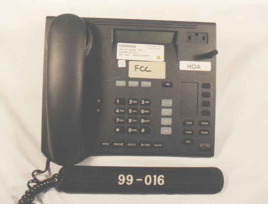
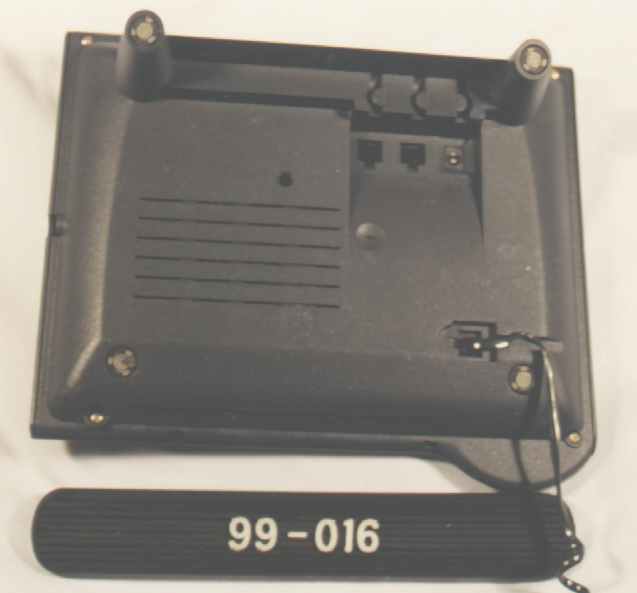
L82-228870Cordless Phone Base Station
Siemens Information and Communication Mobile LLC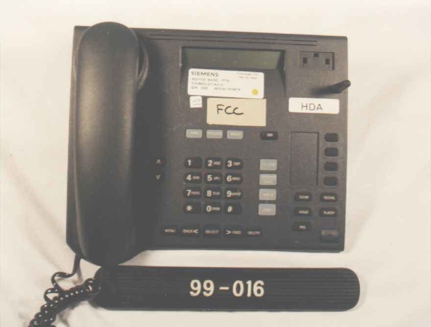
Click to zoom
Application Details
- Equipment Class
- DSS - Part 15 Spread Spectrum Transmitter
- Date of Grant
- Sep 30, 1998
- Application Purpose
- Original Equipment
- Date of Application
- Jul 25, 1998
- Equipment Note
- Cordless Phone Base Station
- Frequency Range
- 2401.05000000 - 2482.27000000
- Country
- United States
Documents & Files
Document Text
Text extracted from the exhibit documents filed with the FCC. Open a document above to read the original.
Users Manual
Siemens Wireless Terminals July 1998 Siemens is a registered trademark of Siemens AC. Siemens Wireless Terminals is a division of Siemens Business Communication Systems Inc. RBRC is a trademark of the Rechargeable Battery Recycling Corporation. Information subject to change since Siemens reserves the right, without notice, to make changes in equipment design or components as progress in engineering or manufacturing methods warrant. Order Number: PB242010 Part Number: A30883-N1-A1-1 Siemens l998 ALL RIGHTS RESERVED Table of Contents IMPORTANT SAFETY INSTRUCTIONS AND PRODUCT INFORMATIONV 1. INSTALLATION1 CONTENTS OF SYSTEM BOX1 STEPS FOR INSTALLATION2 QUICK START7 HOW TO REACH US11 2. THE BASICS13 GENERAL INFORMATION14 DESK STATION16 CORDLESS HANDSET22 3. MAKING, ANSWERING, AND TERMINATING CALLS 27 MAKING CALLS27 ANSWERING CALLS22 TERMINATING CALLS35 4. MANAGING CALLS37 HOLD37 TRANSFER29 CONFERENCE39 CALL BARGE IN41 5. DIRECTORY AND CALL LOG43 DIRECTORY43 CALL LOG54 6. ANSWERING SYSTEM63 GETTNG STARTED63 USING THE ANSWERING SYSTEM FROM THE DESK STATION64 USING THE ANSWERING SYSTEM FROM THE CORDLESS HANDSET OF AN EXTERNAL LINE71 7. CUSTOMIZING YOUR SYSTEM73 DESK STATOINS VOLUME KEY MENUS73 DESK STATIONS MAI N MENU74 SYSTEN SETTINGS77 CALLER ID CALL LOG84 CORDLESS HANDSET'S MAIN MENU 86 LOAD SETTINGS .91 APPENDIX A - MENU TREES95 DESK STAT ON DREC~ORY MEN TREE95 DESK STATON MENU KEY MENU TREE96 CORDLESS HANDSET MENJ KEY MENU TREE180 ANSWERING SYS~EM MENU TREE182 APPENDIX B- TROUBLESHOOTING105 PROBLEMS WITH THE GIGASET 2420 DESK STATION105 PROBLEMS WITH THE GIGASE- 2420 CORDLESS HANOSE- .108 APPENDIX C - PROGRAMMING WORKSHEETS111 DESK STATION SETTINGS111 ANSWERING SYSTEM SETTINGS113 CORDLESS HANDSET SETTINGS114 INDEX115 Important Safety Instructions and Product Information BEFORE USING YOUR TELEPHONE EQUIPMENT, BASIC SAFETY INSTRUCTIONS SHOULD ALWAYS BE FOLLOWED TO REDUCE THE RISK OF FIRE, ELECTRIC SHOCK AND INJURY TO PERSONS AND DAMAGE TO PROPERTY. 1.Read and understand all instructions. 2.Follow all warnings and instructions including those marked on the product. 3.Unplug this product from the wall telephone jack and power outlet before cleaning. Do not use liquid cleaners or aerosol cleaners. Use damp cloth for cleaning. 4.Do not use the desk station near water, for example, near a bathtub, wash bowl, kitchen sink, or laundry tub, in a wet basement or near a swimming pool. B.Do not place this product on an unstable cart, stand or table. The product may fall, causing serious damage to the product. 6.Slots or openings in the cabinet and the back and bottom are provided for ventilation, to protect it from overheating. These openings must not be blocked or covered. The openings should never be blocked by placing the product on a bed, or other similar surface. This product should never be placed near or over a radiator or heat register. This product should not be placed in a built-in installation unless proper ventilation is provided. Safety Instructions and Product Information 7.This product should be operated only from the type of power source indicated on the marking label. If you are not sure of the type of power supply to your home, consult your dealer or local power company. 8.Do not overload wall outlets and extension cords as this can result in the risk of fire or electric shock. 9.Never push objects of any kind into this product through cabinet slots as they may touch dangerous voltage points or short out parts that could result in the risk of fire or electric shock. Never spill liquid of any kind on this product. 10.To reduce the risk of electric shock or burns, do not disassemble this product, but take it to qualified service personnel when some service or repair work is required. Opening or removing covers may expose you to dangerous voltages, dangerous electrical current or other risks. Incorrect reassembly can cause electric shock when the appliance is subsequently used. 11.Unplug the desk station from the wall outlet and refer servicing to qualified service personnel under the following conditions: a.If liquid has been spilled into the product. b.If the product has been exposed to rain or water. a.If the product does not operate normally by following the operating instructions. Adjust only those controls that are covered by the operating instructions because improper adjustment of other controls may result in damage and will often require extensive work by qualified service personnel to restore the product to normal operation. d.If the product has been dropped or cabinet has been damaged. e.If the product exhibits a distinct change in performance. 1 2. Avoid using telephone during an electrical storm. There may a remote risk of electrical shock from lightning. 13.Do not use the telephone to report a gas leak in the vicinity of the leak. 14.The antenna on the base of this telephone does not retract. To prevent injury, do not place the telephone where persons can step, trip or fall on the telephone. 15.Do not place metal objects on the antenna. Battery Safety Precautions: To reduce the risk of fire, injury or electric shock, or property damage, and to properly dispose of batteries, please read and understand the following instructions. CONTAINS NICKEL CADMIUM BATTERY. BATTERY NICAD MUST BE RECYCLED OR DISPOSED OF PROPERLY. DO NOT DISPOSE OF IN MUNICIPAL WASTE. 1Only use type AA Nickel-Cadmium (Ni-Cd) or type AA Nickel-Metal Hydride (NiMH) rechargeable batteries in the cordless handset and reserve battery compartment. DO NOT use other rechargeable batteries or non-rechargeable batteries. The batteries could short-circuit, and the battery shell may be damaged causing a hazardous condition. Instruction labels are located in the handset and charging unit battery compartment. 2.Always follow basic safety precautions when using and disposing of batteries. Do not dispose of the batteries in a fire; the cells may explode. Do not expose batteries to water. Check with local codes for spe…
Text truncated - open the document above for the full version.
Attestation Statements
September 1, 1998 Federal Communication Commission Equipment Authorization Division, Application Processing Branch 7435 Oakland Mills Road Columbia, MD 21048 Subject:Confidentiality Request for the Siemens Gigaset 2400 Phone System FCC ID Numbers L82-228869 & L82-228870 TO WHOM IT MAY CONCERN Pursuant to Paragraph §0.475(d) of the Commission's Rules (47 C.F.R.) and Section §552(b)(4) of the Freedom of Information Act, Siemens requests confidentiality for the following Exhibits as part of the Equipment Authorization Process for the Siemens Gigaset 2400 Phone System: 1) Exhibit(s) containing the Technical Description of the Product 2) Exhibit(s) containing the Circuit Diagrams The above exhibits contain Siemens' trade secrets and proprietary information that could be of benefit to our competitors regarding the design of our mobile handset. This material is not customarily available to the general public and we request that it be withheld from public inspection. If you have any questions, please feel free to contact me at the address shown below. Sincerely, SIEMENS BUSINESS COMMUNICATIONS Edwin L. Bronaugh Edwin L. Bronaugh, Sr. Eng. Lead, Hardware Design Assurance 2205 Grand Avenue Parkway Austin, TX 78728-3811 email: [email protected] Fax:512-990-6335
Attestation Statements
Federal Communication Commission Equipment Authorization Division, Application Processing Branch 7435 Oakland Mills Road Columbia, MD 21048 September 30, 1998 TO WHOM IT MAY CONCERN Pursuant to Paragraph §0.475(d) of the Commission's Rules (47 C.F.R.) and Section §552(b)(4) of the Freedom of Information Act, Siemens Business Communications requests confidentiality for the following products: FCC ID Number Product Title/Model L82-228869Gigaset 2400 Mobile Handset Unit L82-228870Gigaset 2400 Desk Station Unit For both these products, we request that the following information be held confidential: 1) Electrical Schematics of the Circuitry No other items submitted as part of the equipment authorization filing process are deemed confidential. The above exhibits contain Siemens' trade secrets and proprietary information that could be of benefit to our competitors regarding the design of our mobile handset. This material is not customarily available to the general public and we request that it be withheld from public inspection. If you have any questions, please feel free to contact me at the address shown below. Sincerely, Edwin L. Bronaugh Edwin L. Bronaugh, Sr. Eng. Lead, Hardware Design Assurance Siemens Business Communication Systems 2205 Grand Avenue Parkway Austin, TX 78728-3811 email: [email protected] Fax:512-990-6335
Block Diagram
Block Diagram for 2420DS PMB2920 Codec Line I/F a/b PMB2920 Codec Line I/F a/b MC145480 PCM Codec Partial SLIC a/b Microprocessor (C161RI) RF Receiver RF Transmitter 2.4 GHz ARCOFI PSB2163 Gate Array 2X24 Display (4) (4) Audio Audio I 2 C (2) (2) (2) (2) 1MX8 128KX8 32KX8 EEPROM SAM 2MX8 (8) 5X8 Key Matrix (3) Contrast Control (1) (13) (3) Mem Ctrl. Serial Test Port Serial 5/13 MHz (Speech) 10.368MHz Oscillator Headset_Sense (to CPU) T e l c o (8)LEDs (2) Power Supply (1) (2) Resets Adjunct (8) (7) Headset Handset PSB2168 Addr (8) Data SCI (22) (4) IOM2 (1) 29.4912 MHz Oscillator Flash Memory (2) ROM SRAM (4) (2) RSSI Power- On Reset Reset In (2) Reset In 10.368 MHz (4) PMB4729 PCM I/F DECT Analog I/F IOM2 I/F DSP Module BMC Module Microcontroller Interface 4 Ch. (10) Int/Ext a/b Control Lines
Block Diagram
Block Diagram for 2420DS PMB2920 Codec Line I/F a/b PMB2920 Codec Line I/F a/b MC145480 PCM Codec Partial SLIC a/b Microprocessor (C161RI) RF Receiver RF Transmitter 2.4 GHz ARCOFI PSB2163 Gate Array 2X24 Display (4) (4) Audio Audio I 2 C (2) (2) (2) (2) 1MX8 128KX8 32KX8 EEPROM SAM 2MX8 (8) 5X8 Key Matrix (3) Contrast Control (1) (13) (3) Mem Ctrl. Serial Test Port Serial 5/13 MHz (Speech) 10.368MHz Oscillator Headset_Sense (to CPU) T e l c o (8)LEDs (2) Power Supply (1) (2) Resets Adjunct (8) (7) Headset Handset PSB2168 Addr (8) Data SCI (22) (4) IOM2 (1) 29.4912 MHz Oscillator Flash Memory (2) ROM SRAM (4) (2) RSSI Power- On Reset Reset In (2) Reset In 10.368 MHz (4) PMB4729 PCM I/F DECT Analog I/F IOM2 I/F DSP Module BMC Module Microcontroller Interface 4 Ch. (10) Int/Ext a/b Control Lines
Block Diagram
Block Diagram for 2420DS PMB2920 Codec Line I/F a/b PMB2920 Codec Line I/F a/b MC145480 PCM Codec Partial SLIC a/b Microprocessor (C161RI) RF Receiver RF Transmitter 2.4 GHz ARCOFI PSB2163 Gate Array 2X24 Display (4) (4) Audio Audio I 2 C (2) (2) (2) (2) 1MX8 128KX8 32KX8 EEPROM SAM 2MX8 (8) 5X8 Key Matrix (3) Contrast Control (1) (13) (3) Mem Ctrl. Serial Test Port Serial 5/13 MHz (Speech) 10.368MHz Oscillator Headset_Sense (to CPU) T e l c o (8)LEDs (2) Power Supply (1) (2) Resets Adjunct (8) (7) Headset Handset PSB2168 Addr (8) Data SCI (22) (4) IOM2 (1) 29.4912 MHz Oscillator Flash Memory (2) ROM SRAM (4) (2) RSSI Power- On Reset Reset In (2) Reset In 10.368 MHz (4) PMB4729 PCM I/F DECT Analog I/F IOM2 I/F DSP Module BMC Module Microcontroller Interface 4 Ch. (10) Int/Ext a/b Control Lines
Cover Letter(s)
Federal Communication Commission Equipment Authorization Division, Application Processing Branch 7435 Oakland Mills Road Columbia, MD 21048 TO WHOM IT MAY CONCERN Siemens Business Communications authorizes Professional Testing (EMI) Inc., to operate on its behalf for application filing with the FCC on the following products: FCC ID NumberProduct Title/Model L82-228869CCS2420 Mobile Handset Unit L82-228870CCS2420 Base Unit If you have any questions, please feel free to contact me at the address shown below. Sincerely, SIEMENS BUSINESS COMMUNICATIONS Edwin L. Bronaugh Edwin L. Bronaugh, Sr. Eng. Lead, Hardware Design Assurance 2205 Grand Avenue Parkway Austin, TX 78728-3811 email: [email protected] Fax:512-990-6335
Test Report
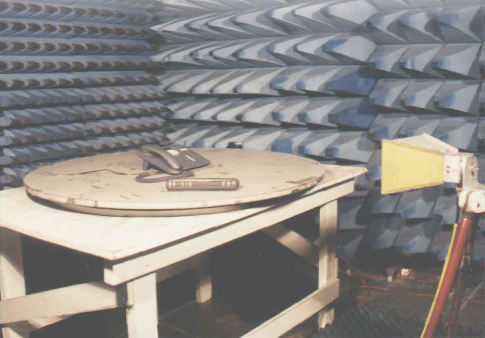
FCC ID# L82-228870 FCC ID: L82-228870 Prepared for: SIEMENS BUSINESS COMMUNICATIONS 2205 Grand Avenue Austin, Texas 78728-3811 By: Professional Testing (EMI), Inc. 1601 FM 1460, Suite B Round Rock, Texas 78664 Submitted to: Federal Communications Commission Equipment Authorization Division, Application Processing Branch 7435 Oakland Mills Road Columbia, MD 21048 August 1998 FCC Type Certification Test Report of an Intentional Radiator SIEMENS BUSINESS COMMUNICATION SYSTEMS GigaSet 2400HS Spread Spectrum Cordless Phone System Desk Station (Transmitter Portion) FCC ID# L82-228870 Professional Testing (EMI), Inc. 2 of 34 Table of Contents Title Page ..............................................................................................................................................1 Table of Contents...................................................................................................................................2 Certificate of Compliance......................................................................................................................4 Appendices...........................................................................................................................................3 1.0Equipment Under Test (EUT) Description..................................................................................5 1.1Equipment Under Test (EUT) Operation.....................................................................................6 2.0Occupied Bandwidth Measurements...........................................................................................6 2.1Test Procedure..............................................................................................................................6 2.2Test Criteria..................................................................................................................................7 2.3Test Results...................................................................................................................................7 3.0Hop Frequency Quantity..............................................................................................................7 3.1Evaluation Procedure....................................................................................................................7 3.2Evaluation Criteria........................................................................................................................7 3.3Evaluation Results........................................................................................................................8 4.0Average Time of Occupancy........................................................................................................8 4.1Test Procedure..............................................................................................................................8 4.2Test Criteria..................................................................................................................................8 4.3Test Results...................................................................................................................................8 5.0Peak Output Power.......................................................................................................................8 5.1Measurement Procedure...............................................................................................................9 5.2Evaluation Criteria........................................................................................................................9 5.3Evaluation Results........................................................................................................................9 6.0Out-of-Band Emission Measurements.........................................................................................9 6.1Test Procedure..............................................................................................................................9 6.2Test Criteria................................................................................................................................10 6.3Test Results.................................................................................................................................10 7.0Conducted Emissions Measurements.........................................................................................10 7.1Test Procedure............................................................................................................................10 7.2Test Criteria................................................................................................................................10 7.3Test Results.................................................................................................................................11 8.0Frequency Stability Measurements............................................................................................11 8.1Test Procedure............................................................................................................................11 8.2Test Criteria................................................................................................................................11 8.3Test Results.................................................................................................................................11 9.0Antenna Requirement.................................................................................................................12 9.1Evaluation Procedure..................................................................................................................12 9.2Evaluation Criteria......................................................................................................................12 9.3Evaluation Results..........................................................................................…
Text truncated - open the document above for the full version.
Test Report
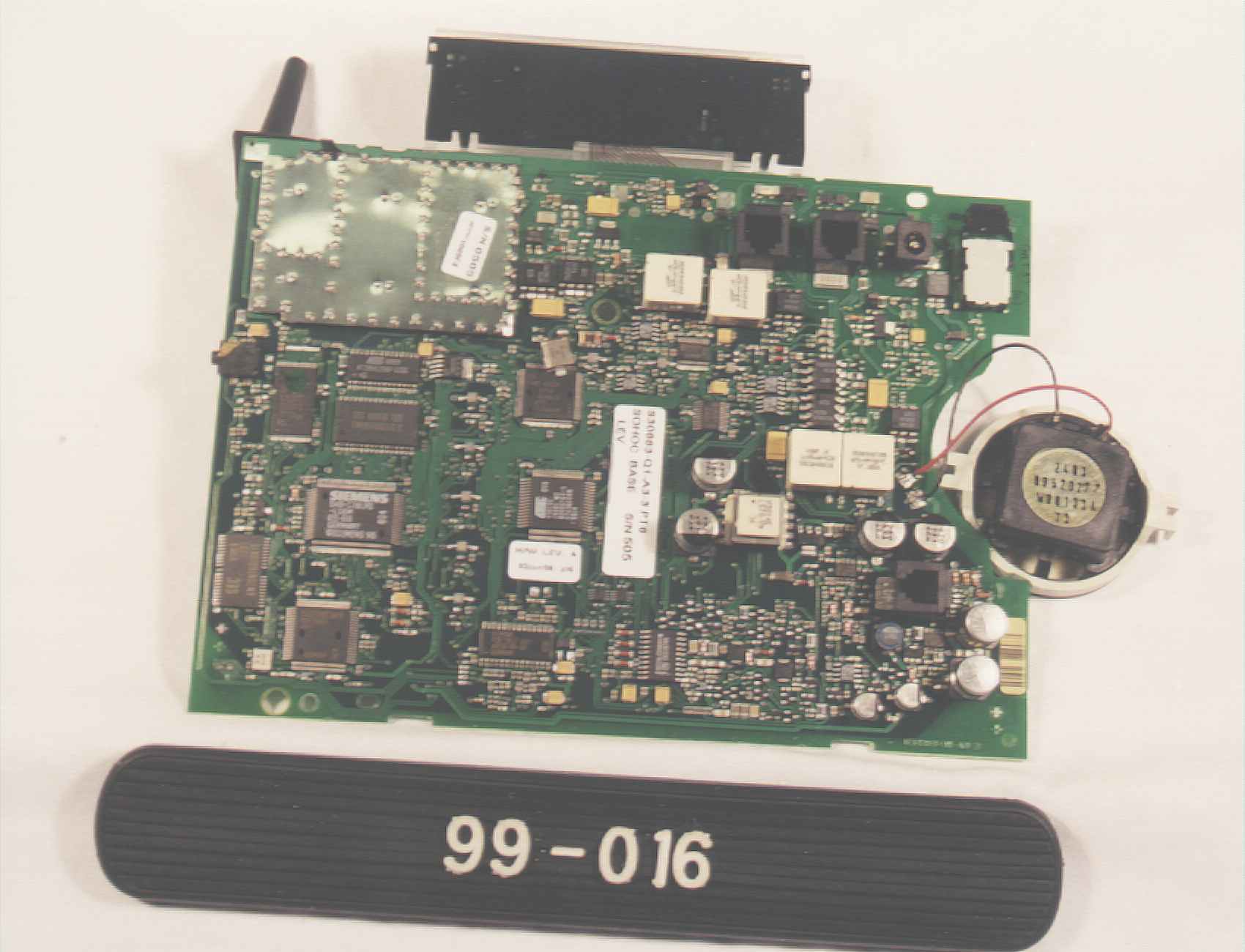
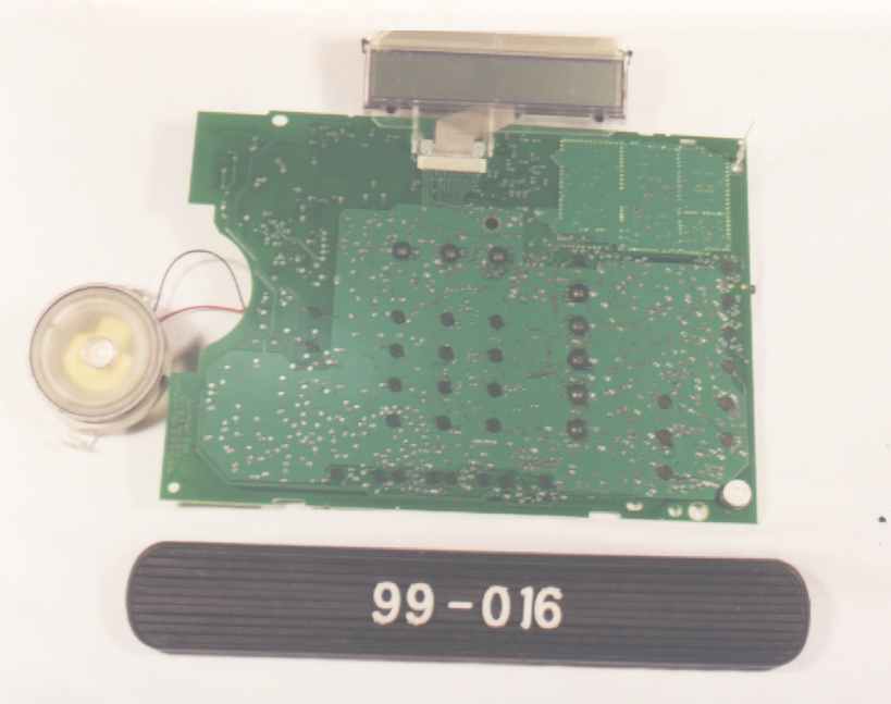
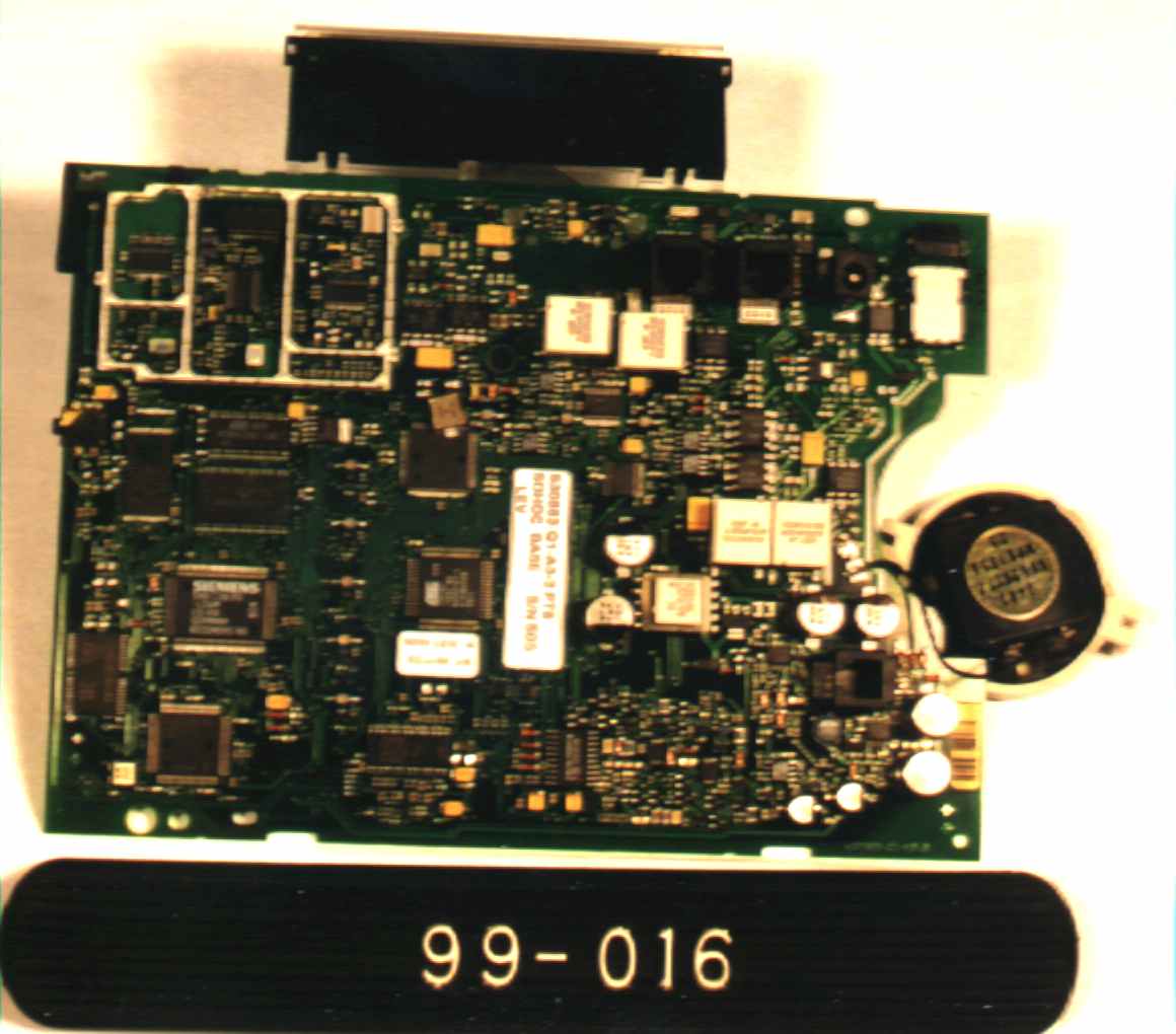
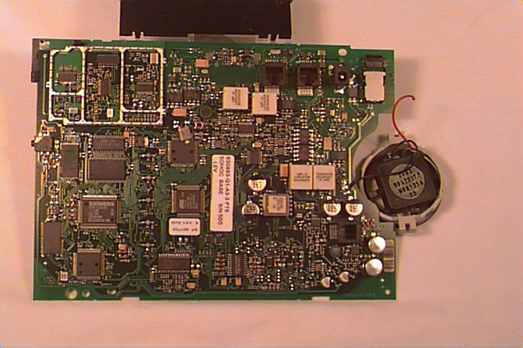
1 FCC APPLICATION INQUIRY RESPONSE L82-228870: SIEMENS GIGASET 2400 DESK STATION Correspondence Number: 3392 September 17, 1998 1.0 Overview This package was compiled to reply to inquiries made by Mr. Joe Dichoso of the FCC regarding the Type Certification Application for the Siemens Gigaset 2400 Desk Station. Each Inquiry item is listed below followed by the response. 2.0 Inquiry Responses (1) The confidential letter requests only the technical description and the schematic to be held confidential. No technical description was submitted. Two block diagrams were submitted but one was marked confidential and the other was not. Please verify & correct this situation. Answer: A copy of the technical description of the Gigaset 2400 Desk Station is was submitted to the Commission via the ‘add attachments’ option on the electronic filing site on September 17, 1998. The technical description has been revised such that it is no longer Siemens-Confidential. The only portion of this application that should be confidential are the schematics. The correct block diagram was forwarded to the Commission via the ‘add attachments’ option of the electronic filing site on September 17, 1998. (2) The photo of the main board was dark & unfocused. Please submit a clear photo. Answer: Photos of the front & back of the main board were retaken & resubmitted to the Commission via the ‘add attachments’ option on the electronic filing site on September 16, 1998. The main board without the shield was not re-photographed but can be if need. (3) Please show compliance with the 20 dB down requirement at the band edges, when the device is in the highest and lowest channels. Also show compliance with the restricted band requirements (15.205) for the 2483.5 to 2500 MHz restricted band. 2 Answer: Plots of emission bandwidth were taken of the device at the highest and lowest channels and are included in Appendix A of this attachment. A data sheet indicating radiated emission measurements at the low end of the 2483.5 MHz Restricted band are also contained in this Appendix. Based on the measurement procedures contained in Section 15.205 for signals above 1 GHz, the Siemens 2400 Desk Station is compliant with this specification. (4) The 20 dB bandwidth was 903 kHz while the channel separation was only 864 kHz. The channels must be separated by atleast the 20 dB bandwidth. Try using a smaller but appropriate RBW for the 20 dB bandwidth measurement. Answer: The occupied bandwidth was remeasured at bottom, top and middle of the transmit band using a 30 kHz RBW and 100 kHz VBW. Lowering the RBW provides better resolution of the spectrum for a ~700 kHz bandwidth signal. (5) Section 15.247(a)(1) indicates that the system receivers shall have input bandwidths thatn match the hopping channel bandwidths of their corresponding transmitters and shall shift frequencies with the transmitted signals. Please explain how the device complies withthis rule when a packet is repeated or when multiple packets are sent. What is the receiver input bandwidth? How does the receiver shift frequencies and determine which frequencies to shift to in order to synchronize with this transmitter. Answer: The IF bandwidth determines the receiver bandwidth. The IF bandwidth at 3 dB down is 700 kHz. This is equal to the bandwidth of the transmitter. Each base has its own pseudo random hopping sequence. When the mobile is registered with a base, it is given the same hopping sequence and is thus synchronized with that base. Any blocked frequencies are told to the mobile by the base. The phone does not repeat packets, and it does not use multiple packets. Bad packets are dropped. (6) Please provide the calculation method used for RF Output Power. Answer: Calculation of the output power in watts is based on the following formula found in Industry Canada NIR-E document: 3 Power (ERP) = (E * r) / (30) 1/2 Where: E = radiated electric field level in V/m r = distance from the EUT to the measurement antenna The method used in this application to calculate ERP goes through the following steps: (a) Determine the peak level in dBμV/m (b) Translate this level to μV/m using the following formula μV/m = 10^((dbμV/m)/20) (c) Translate this level to V/m by dividing by 1X10 6 (d) Calculate ERP based on the formula at the beginning of this section for a test distance of X meters. (7) How does this device comply with the RF Safety Requirements? Answer: Based on a conversation with Kwok Chan of the Commission on September 16, 1998, the following RF Safety analysis is provided: The power used for evaluation to the RF Safety Hazard Specification can be derated based on the percentage that the transmit signal is actually present over time. For the Gigaset 2400 Desk Station, the duty cycle of the transmit signal over time is 1/8. The Power level used for comparison to the OET-65C limit can be calculated as follows: Ref. Power = (Peak Power) * (Duty Cycle) = (0.469 watts) * ( 1/8) = 0.0586 watts This figure is below the threshold (<0.2 watts at 2450 MHz for cordless phone handsets and most other trasnmitters using monopole or dipole type antennas as an integral part of the device) for this device. The Gigaset 2400 Desk Station uses an integral monopole antenna. Based on this criteria, special warnings or instructions are not required to show compliance for this device. (8) Indicate the manufacturer of the Spread Spectrum Chip. Answer: The manufacturer of the spread spectrum chip is Siemens Semiconductors, Munich, Germanuy. The parts used are a PMB 4729 for the Gigaset 2400 Desk Station and a PMB 4724 for the Gigaset 2400 Handset. 4 (9) The transmitter cannot coordinate its hopping sequence with the hopping sequence of other transmitters, or vice versa, for the purpose of avoiding simultaneous occupancy of individual hopping frequencies by multiple transmitters. Provide a description on how the device complies with this rule. Answer: The hopping frequency sequence is determined by the uni…
Text truncated - open the document above for the full version.
Test Report
1 FCC APPLICATION INQUIRY RESPONSE L82-228870: SIEMENS GIGASET 2400 DESK STATION Correspondence Number: Unknown September 24, 1998 1.0 Overview This package was compiled to reply to inquiries made by Mr. Joe Dichoso of the FCC regarding the Type Certification Application for the Siemens Gigaset 2400 Desk Station. Each Inquiry item is listed below followed by the response. 2.0 Inquiry Responses (1) Based on the bandwidth plot of the device, transmitting on Channel 95, the device is not 20 dB down at the bandedge of 2843.5 MHz. It is only 10 dB down at the bandedge. Also, if the peak radiated field strength of the fundimental is 128 dBuV/m, the peak field strength at the restricted band frequency is 118 dBuv/m, (128-10 = 118 dBuv/m). This is 44 dB above the peak limit of 74 dBuV/m. Please correct/explain. Answer: The original version of Part 15 (Oct 1996) version that we were using showed the limit for this section (15.247(c)) shall be either 20 dB down or meet 15.209, whichever has the least attenuation. The revised (July 1998) version of this document states the 20 dB criteria without a ‘least attenuation’ criteria. The appropriate portions of 15.205 must also be met. Following the last correspondence regarding this application, an inspection of the EUT was made. It was found that the cover of the RF compartment on the device was notsecured properly. This was corrected and the bandedge and occupied bandwidth tests redone. All bandedges are now within the 20 dB criteria. The occupied bandwidth still meets the requirements of the Rules. All of these tests were made with the EUT in fixed freuqency mode. Measurements of the emissions of the EUT in fixed frequency mode set to Channel 95 were made at the base of this restricted band. Measurements were made using average detection criteria in accordance with Section 15.205 (b) of the Rules (measurement above 1 GHz). All emissions in this area were below the 15.205/15.209 limit. Data indicating compliance with the 15.205 restricted band is included with this submission. (2) Redo the output power tests with the EUT in fixed transmit (non-hopping) mode. Perform the ERP calculation based on the following formula: 2 P(EIRP) = {(E * d)^2 } / 30 Answer: Radiated emissions data for Channels 00, 46 and 95 are included with this document. Calculations of ERP based on the corrected formula are included with this data. We request that the Comission correct the 731 data as necessary. For all measurements, the test distance was 1 meter. (3) Re-evaluation the RF Safety issue based on the revised EIRP results. Answer: Based on a conversation with Kwok Chan of the Commission on September 16, 1998, the following RF Safety analysis is provided: The power used for evaluation to the RF Safety Hazard Specification can be derated based on the percentage that the transmit signal is actually present over time. For the Gigaset 2400 Desk Station, the duty cycle of the transmit signal over time is 1/8. The Power level used for comparison to the OET-65C limit can be calculated as follows: Ref. Power = (Peak Power) * (Duty Cycle) = (0.192 watts) * ( 1/8) = 0.024 watts This figure is below the threshold (<0.2 watts at 2450 MHz for cordless phone handsets and most other trasnmitters using monopole or dipole type antennas as an integral part of the device) for this device. The Gigaset 2400 Desk Station uses an integral monopole antenna. Based on this criteria, special warnings or instructions are not required to show compliance for this device. (4) Resend the Photo to the L82-228870 file Answer: Photo was resent on September 24, 1998. 3 APPENDIX EIRP AND RESTICTED BAND DATA 4 Radiated Data Sheet Siemens Business Communication Systems Gigaset 2420HS Desk Station SERIAL #:505MEASUREMENT DISTANCE (m): 1 DATE: Septmber 24, 1998MEASUREMENT HEIGHT: 1 meter PROJECT #: 99-016EUT Orientation: 180 EIRP Freq.ChannelRecordedAntennaCableCorrectedEIRP SettingLevelFactorLossLevel (MHz)(dBuV)(dB/m)(dB)(dBuV/m)(Watts) 2401.00.097.726.81.6126.10.1358 2440.846.098.026.81.6126.40.1455 2483.195.099.226.81.6127.60.1918 Corrected Level = Recorded Level + Antenna Factor + Cable Loss COMMENT #1: All measurements for this test based on peak measurement methods COMMENT #2: TEST ENGINEER:______________________ APPROVED BY: ______________________ John O’BrienJeffery Lenk 5 Radiated Data Sheet Siemens Business Communication Systems Gigaset 2420HS Desk Station SERIAL #:505MEASUREMENT DISTANCE (m): 1 DATE: Septmber 16, 1998MEASUREMENT HEIGHT: 1 meter PROJECT #: 99-016EUT Orientation: 180 RESTRICTED BAND TEST Freq.NotesRecordedAntennaCableCorrectedLimitMargin and LevelFactorLossLevel (MHz)Polarization(dBuV)(dB/m)(dB)(dBuV/m)(dBuV/m)(dB) 2483.5(1) Vertical26.526.81.654.963.5-8.6 2483.5(1) Horizontal26.226.81.654.663.5-8.9 Corrected Level = Recorded Level + Antenna Factor + Cable Loss COMMENT #1: All measurements are average measurements COMMENT #2: Test Distance 1 meter TEST ENGINEER:______________________ APPROVED BY: ______________________ John O’BrienJeffery Lenk 6 Occupied Bandwidth Data Sheet Siemens Business Communication Systems Gigaset 2420HS Desk Station SERIAL #:505PROJECT #: 99-016 DATE: September 24, 1998 COMMENT #1: Channel Setting = 00 COMMENT #2: 20dB Bandwidth = 685 kHz TEST ENGINEER:______________________ APPROVED BY: ______________________ John O’BrienJeffrey Lenk 7 Occupied Bandwidth Data Sheet Siemens Business Communication Systems Gigaset 2420HS Desk Station SERIAL #:505PROJECT #: 99-016 DATE: September 24, 1998 COMMENT #1: Channel Setting = 46 COMMENT #2: 20dB Bandwidth = 683 kHz TEST ENGINEER:______________________ APPROVED BY: ______________________ John O’BrienJeffrey Lenk 8 Occupied Bandwidth Data Sheet Siemens Business Communication Systems Gigaset 2420HS Desk Station SERIAL #:505PROJECT #: 99-016 DATE: September 24, 1998 COMMENT #1: Channel Setting = 95 COMMENT #2: 20dB Bandwidth = 708 kHz TEST ENGINEER:______________________ APPROVED BY: ______________________ John O’BrienJeffrey L…
Text truncated - open the document above for the full version.
Test Report
1 FCC APPLICATION INQUIRY RESPONSE L82-228870: SIEMENS GIGASET 2400 DESK STATION Correspondence Number: None September 29, 1998 1.0 Overview This package was compiled to reply to inquiries made by Mr. Joe Dichoso of the…
Text truncated - open the document above for the full version.
Contact Information
Applicant
Mauricio da Silva(Director, Quality)
Technical Contact
Siemens Business Commincations SystemsEdwin Bronaugh
[email protected](512) 990-1000
2205 Grand Avenue Parkway · Austin, Texas · United States
Non-Technical Contact
Same as Item 6
(512) 990-1000
Test Firm
Professional Testing (EMI) Inc.Jeffrey Lenk
Technical Specifications
| # | Rule Parts | Frequency Range | Power Output |
|---|---|---|---|
| 1 | 15C | 2.40 GHz - 2.48 GHz | 180.00 mW |
Other Applications from Siemens Information and Communication Mobile LLC

L82-S44
Oct 20, 2005Cordless Phone Handset
Equipment Class
PUE - Part 15 Unlicensed PCS portable Tx held to ear
L82-S445
Oct 20, 2005Cordless Phone Base Station
Equipment Class
PUB - Part 15 Unlicensed PCS Base Station
L82-SL3501
Feb 12, 2003Spread Spectrum Cordless Phone System
Equipment Class
DSS - Part 15 Spread Spectrum Transmitter
L82-BIRD
Nov 24, 20022.4 GHz DECT Cordless Telephone System
Equipment Class
DSS - Part 15 Spread Spectrum Transmitter
L82-HOME-RF-4000
Feb 06, 2002Spread Spectrum Cordless Phone Handset Transceiver
Equipment Class
ETR - Part 15 Cordless Telephone Remote Transceiver