L9V-COMTREND5834Wireless Extender
Comtrend Corporation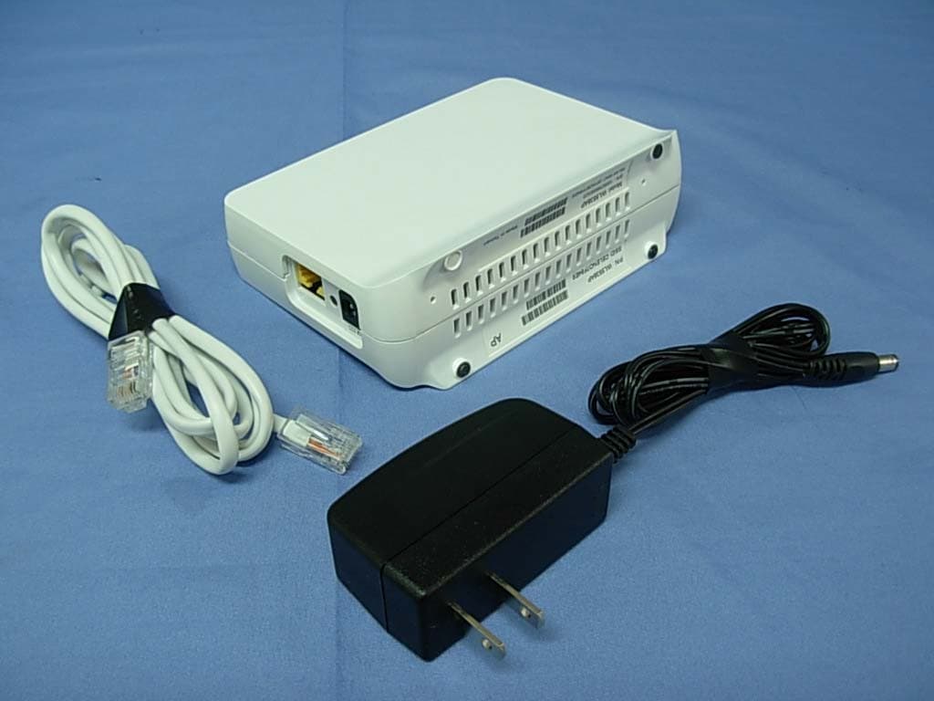
Click to zoom
Application Details
- Equipment Class
- NII - Unlicensed National Information Infrastructure TX
- Date of Grant
- Oct 12, 2010
- Application Purpose
- Original Equipment
- Date of Application
- Oct 11, 2010
- Equipment Note
- Wireless Extender
- Frequency Range
- 5190.00000000 - 5230.00000000
- Company
- Comtrend Corporation
- Country
- Taiwan
Documents & Files
Document Text
Text extracted from the exhibit documents filed with the FCC. Open a document above to read the original.
Users Manual
1 Introduction This Quick Installation Guide will help you to quickly and easily install your Wireless Extender units by performing the few simple steps described below. Before you begin, check that you have: • One WAP-5834 Access Point unit (An “AP” is stated in chassis label) • One WAP-5834 Client unit (A “Client” is stated in chassis label) • Two CAT5 ETHERNET cables • Two power adapters • One Quick Installation Guide Easy Link Step 1 - Power connection Plug in the power adapter included in your package, and connect it to the WAP-5834 AP and Client device. QUICK INSTALLATION GUIDE WAP-5834 Wireless Extender 2 Using a power supply with different voltage rating than the one included with the WAP-5834 device may cause damage and void the warranty for this product. Step 2 - Placement and connections The WAP-5834 AP and Client device in your package are pre-configured to work together. Place the WAP-5834 AP device on an easily accessible surface near the Home Gateway or Cable/DSL Modem. A. Plug one end of the Ethernet cable into the LAN port of the gateway device and the other end into the Ethernet port of the WAP-5834 AP. LAN RESET DC-IN Home Gateway LAN RESET DC-IN LAN 4 x LAN 3 xLAN 2 x LAN 1 x ADSL Intermet Power 3 Make sure that the LED on the WAP-5834 AP is flashing blue. Place the WAP-5834 Client device on an easily accessible surface near the set top box. B. Plug one end of the Ethernet cable into the LAN port of the set top box device and the other end into the Ethernet port of the WAP-5834 Client. Make sure that the LED on the WAP-5834 Client is flashing blue. For best wireless performance place the devices on a shelf or other elevated location and away from large metallic objects. Wireless WPS LAN Power LAN LAN Wireless WPS LAN Power LAN RESET DC-IN Set Top Box STB-7007 IR STA TUS WAN 4 Congratulations! You have finished installing your new Wireless Extender devices. To test your connectivity, turn on the TV and set top box, then watch any available TV channel. Pairing The WAP-5834 AP and Client device in your package are pre-configured to work together. To add additional WAP-5834 Clients you will need to perform the pairing procedures as explained below. Place the WAP-5834 Client device between 1 to 3 meters from the WAP-5834 AP device. Step 1. Pair the devices: Press the WPS button on the “AP” front panel for 3-5 seconds and release it. The LED will begin flashing blue. Press the WPS button on the “Client” for 3-5 seconds and release it. The LED will begin flashing blue. NOTE – The WPS buttons can be pressed in any order as long as they are pressed within 2 minutes from each other. WPS WPS Wireless WPS LAN Power WPS Button 5 Step 2. Wait for the pairing process to complete by watching the LEDs on the devices: The LEDs will flash blue for a few seconds. After successful pairing the LEDs will change to solid blue, and after two minutes turn off. The LEDs will then be solid blue. If pairing is unsuccessful, the LED will flash blue for two minutes. Troubleshooting • The LED is not on Make sure that: • The power cord is connected to the device, and that the power adapter is properly connected to a functioning power outlet. • You are using the power adapter that was supplied with the product. • The LED is not on Make sure that: • The LAN cable connectors are securely plugged in at the Wireless Video Extender device and at the network device (gateway, modem or set top box). • The connected network device is turned on. • You are using the correct cable type for your Ethernet equipment, which is at least UTP CAT5 with RJ45 connectors. Wireless WPS WPS WPS LAN Power Wireless WPS 6 Advanced Setting The instructions below are for users who have a basic Network knowledge. Users are not encouraged to configure the following settings because this may cause irreversible damage. Change AP or Client mode This is to enable users to change WAP-5834 to AP or Client in a real situation. Note: • If you are connecting to the WAP-5834 directly from a PC, be sure to set a static IP in the same range as the AP or Client unit (e.g. 10.0.0.25) to access the Web Configuration page. • If the WAP-5834 is connected to a Gateway or Router that has a DHCP server, it will automatically get an IP address from that device. Be sure to check your Gateway or Router to see what IP address was given to the WAP-5834 units and use that to log in to the Web Configuration page. Step 1. Enter into WAP-5834 Web GUI through browsers such as IE with default IP 10.0.0.2 for AP and 10.0.0.10 for Client. Step 2. Type default username and password: root/12345 Step 3. Change the Operation Mode to Access Point or Client in the “Operation Mode” drop-down menu and press the “Apply” button. 7 Advanced Troubleshooting • The WPS function is not working Make sure that: • The WPS function is activated in the AP device. a. Enter into WAP-5834 AP Web GUI through browsers such as IE by default IP address 10.0.0.2. b. Type default username and password: root/12345 c. Change the security mode to WPA2-PSK in Security Settings by selecting it in the drop-down menu. 8 d. Enable WPS in WPS setting and press the “Apply” button. • Complete the pairing procedures as described in the Pairing section. • The LED is not on • Make sure that you have completed a successful pairing procedure as described in the Pairing section. FOR MORE HELP: If you have further questions or require personal assistance, please contact your equipment provider. Wireless This equipment also should be installed and operated with minimum distance 20cm between the radiator & your body.
External Photos
Report No:106293R-RFUSP46V01 Page: 100 of 105 Attachement EUT Photograph (1) EUT Photo (2) EUT Photo
ID Label/Location Info
Comtrend Corporation 3F-1, 10 Lane 609, Chung Hsin Road, Section 5, San Chung City, Taipei County 24159, Taiwan FCC ID.: L9V-COMTREND5834 FCC ID AND DoC Label
Internal Photos
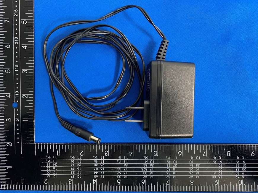
Report No:106293R-RFUSP46V01 Page: 101 of 105 (3) EUT Photo (4) EUT Photo Report No:106293R-RFUSP46V01 Page: 102 of 105 (5) EUT Photo (6) EUT Photo Report No:106293R-RFUSP46V01 Page: 103 of 105 (7) EUT Photo (8) EUT Photo Report No:106293R-RFUSP46V01 Page: 104 of 105 (9) EUT Photo Report No:106293R-RFUSP46V01 Page: 105 of 105 (10) EUT Photo (ANT) (11) EUT Photo (Adapter)
RF Exposure Info
Report No. 106293R-RF-US-Exp Page: 1 of 3 RF Exposure Evaluation declaration Product Name :Wireless Extender Model No. :BeamLink 5834, CT-5834, 5834, WL5538AP, WAP-5834 FCC ID. :L9V-COMTREND5834 Applicant : Comtrend Corporation Address : 3F-1, 10 Lane 609, Chung Hsin Road, Section 5, San Chung City, Taipei County 24159, Taiwan Date of Receipt : 2010/06/17 Date of Declaration : 2010/09/17 Report No. : 106293R-RF-US-Exp Report Version : V1.0 The declaration results relate only to the samples calculated. The declaration shall not be reproduced except in full without the written approval of QuieTek Corporation. Report No. 106293R-RF-US-Exp Page: 2 of 3 1. RF Exposure Evaluation 1.1. Limits According to FCC 1.1310: The criteria listed in the following table shall be used to evaluate the environment impact of human exposure to radio frequency (RF) radiation as specified in 1.1307(b) LIMITS FOR MAXIMUM PERMISSIBLE EXPOSURE (MPE) Frequency Range (MHz) Electric Field Strength (V/m) Magnetic Field Strength (A/m) Power Density (mW/cm 2 ) Average Time (Minutes) (A) Limits for Occupational/ Control Exposures 300-1500 -- -- F/300 6 1500-100,000 -- -- 5 6 (B) Limits for General Population/ Uncontrolled Exposures 300-1500 -- -- F/1500 6 1500-100,000 -- -- 1 30 F= Frequency in MHz Friis Formula Friis transmission formula: Pd = (Pout*G)/(4*pi*r 2 ) Where Pd = power density in mW/cm 2 Pout = output power to antenna in mW G = gain of antenna in linear scale Pi = 3.1416 R = distance between observation point and center of the radiator in cm Pd id the limit of MPE, 1 mW/cm 2 . If we know the maximum gain of the antenna and the total power input to the antenna, through the calculation, we will know the distance r where the MPE limit is reached. 1.2. Test Procedure Software provided by client enabled the EUT to transmit and receive data at lowest, middle and highest channel individually. The temperature and related humidity: 18°Cand 78% RH. Report No. 106293R-RF-US-Exp Page: 3 of 3 1.3. Test Result of RF Exposure Evaluation Product Wireless Extender Test Mode Mode 1: Transmit Test Condition RF Exposure Evaluation Antenna Gain Antenna Gain: The maximum Gain measured in fully anechoic chamber is 2dBi or 1.58 in linear scale. Output Power into Antenna & RF Exposure Evaluation Distance: IEEE 802.11n(20MHz) WLAN Function Channel Channel Frequency (MHz) Output Power to Antenna (mW) Power Density at R = 20 cm (mW/cm 2 ) 36 5180 25.7040 0.00808 44 5220 26.2422 0.00825 48 5240 25.2348 0.00793 149 5745 256.4484 0.08061 157 5785 259.4179 0.08154 165 5825 252.9298 0.07950 IEEE 802.11n(40MHz) WLAN Function Channel Channel Frequency (MHz) Output Power to Antenna (mW) Power Density at R = 20 cm (mW/cm 2 ) 38 5190 44.8745 0.01411 46 5230 45.4988 0.01430 151 5755 243.7811 0.07663 159 5795 244.3431 0.07680 The power density Pd (4th column) at a distance of 20 cm calculated from the Friis transmission formula is far below the limit of 1 mW/cm 2 .
Test Report
Report No:106293R-RFUSP46V01 Page: 1 of 105 Test Report Product Name :Wireless Extender Model No. :BeamLink 5834, CT-5834, 5834, WL5538AP, WAP-5834 FCC ID. :L9V-COMTREND5834 Applicant : Comtrend Corporation Address : 3F-1, 10 Lane 609, Chung Hsin Road, Section 5, San Chung City, Taipei County 24159, Taiwan Date of Receipt:2010/06/17 Issued Date :2010/09/17 Report No. :106293R-RFUSP46V01 Report Version :V1.0 The test results relate only to the samples tested. The test report shall not be reproduced except in full without the written approval of QuieTek Corporation. Report No:106293R-RFUSP46V01 Page: 2 of 105 Test Report Certification Issued Date : 2010/09/17 Report No. : 106293R-RFUSP46V01 Product Name : Wireless Extender Applicant : Comtrend Corporation Address : 3F-1, 10 Lane 609, Chung Hsin Road, Section 5, San Chung City, Taipei County 24159, Taiwan Manufacturer : Ayecom Technology Co., Ltd MODEL NO. : BeamLink 5834, CT-5834, 5834, WL5538AP, WAP-5834 FCC ID. : L9V-COMTREND5834 EUT Voltage : 100-120V~50/60 Hz Trade Name : BeamLink, Comtrend Applicable Standard : FCC CFR Title 47 Part 15 Subpart C Section 15.407:2009 Test Result : Complied The test results relate only to the samples tested. The test report shall not be reproduced except in full without the written approval of QuieTek Corporation. Documented By : ( Demi Chang / Engineering Adm. Specialist ) REVIEWED BY : ( Ben Huang / Assistant Engineer ) Approved By : ( Roy Wang / Manager ) Report No:106293R-RFUSP46V01 Page: 3 of 105 TABLE OF CONTENTS Description Page 1. GENERAL INFORMATION .............................................................................................................................5 1.1. EUT DESCRIPTION.........................................................................................................................................5 1.2. OPERATIONAL DESCRIPTION...........................................................................................................................9 1.3. TEST MODE.................................................................................................................................................10 1.4. TESTED SYSTEM DETAILS............................................................................................................................. 11 1.5. CONFIGURATION OF TESTED SYSTEM............................................................................................................ 11 1.6. EUT EXERCISE SOFTWARE..........................................................................................................................12 1.7. TEST FACILITY.............................................................................................................................................13 2. CONDUCTED EMISSION .............................................................................................................................15 2.1. TEST EQUIPMENT.........................................................................................................................................15 2.2. TEST SETUP................................................................................................................................................15 2.3. LIMITS.........................................................................................................................................................16 2.4. TEST PROCEDURE.......................................................................................................................................16 2.5. TEST SPECIFICATION....................................................................................................................................16 2.6. UNCERTAINTY..............................................................................................................................................16 2.7. TEST RESULT...............................................................................................................................................17 2.8. TEST PHOTO................................................................................................................................................19 3. 26DB BANDWIDTH ......................................................................................................................................20 3.1. TEST EQUIPMENT.........................................................................................................................................20 3.2. TEST SETUP................................................................................................................................................20 3.3. LIMITS.........................................................................................................................................................20 3.4. TEST PROCEDURE.......................................................................................................................................20 3.5. UNCERTAINTY..............................................................................................................................................20 3.6. TEST RESULT...............................................................................................................................................21 4. PEAK TRANSMIT POWER...........................................................................................................................25 4.1. TEST EQUIPMENT.........................................................................................................................................25 4.2. TEST SETUP................................................................................................................................................25 4.3. LIMITS.........................................................................................................................................................26 4.4. TEST PROCEDURE…
Text truncated - open the document above for the full version.
Test Setup Photos
Report No:106293R-RFUSP46V01 Page: 19 of 105 2.8. Test Photo Test Mode : Mode 1: Transmit Description: Front View of Conducted Emission Test Setup Test Mode : Mode 1: Transmit Description: Back View of Conducted Emission Test Setup Report No:106293R-RFUSP46V01 Page: 70 of 105 7.7. Test Photo Test Mode : Mode 1: Transmit Description: Front View of Radiated Emission Test Setup (Bilog) Test Mode : Mode 1: Transmit Description: Back View of Radiated Emission Test Setup (Bilog) Report No:106293R-RFUSP46V01 Page: 71 of 105 Test Mode : Mode 1: Transmit Description: Front View of Radiated Emission Test Setup (Horn) Test Mode : Mode 1: Transmit Description: Backl View of Radiated Emission Test Setup (Horn)
Contact Information
Applicant
Bill Wang
Test Firm
DEKRA TESTING AND CERTIFICATION CO., LTD.Warren Lin
Technical Specifications
| # | Rule Parts | Frequency Range | Power Output |
|---|---|---|---|
| 2 | 15E | 5.19 GHz - 5.23 GHz | 45.40 mW |
Other Applications from Comtrend Corporation
L9VVR3071V2
Nov 30, 2023Home Gateway
Equipment Class
DTS - Digital Transmission System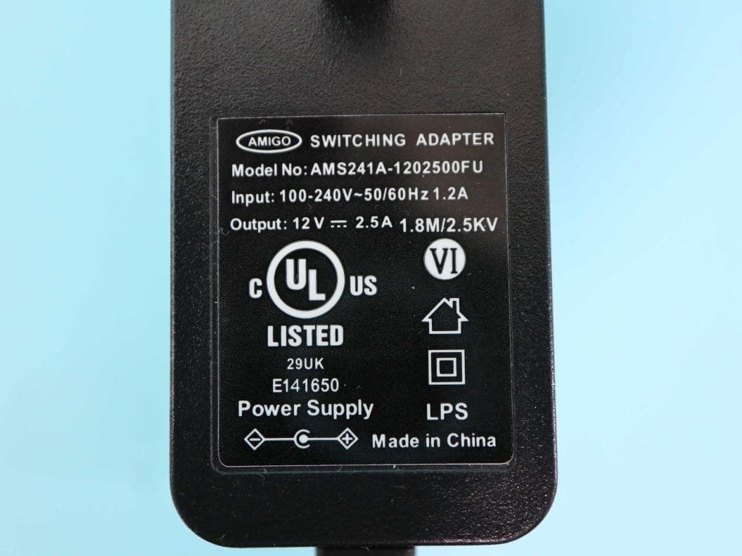
L9VPRT6351
Jul 04, 2023Home Gateway
Equipment Class
DTS - Digital Transmission System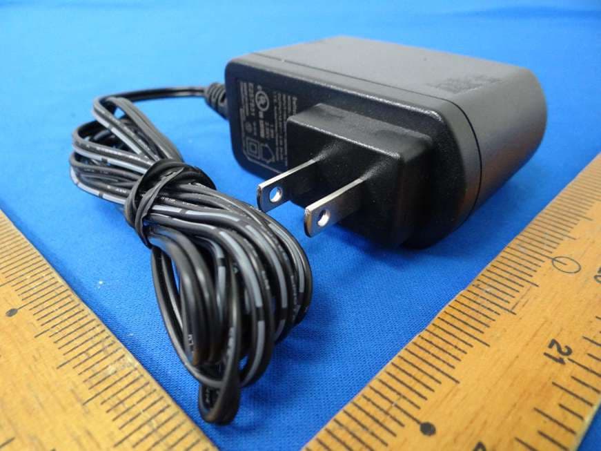
L9VWAP60AXD
Jun 07, 2022Home Gateway
Equipment Class
DTS - Digital Transmission System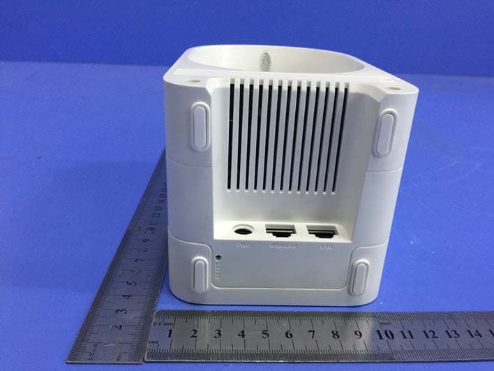
L9VWAP5903
Apr 29, 2020AC1200 Dual Band WiFi Mesh Extender
Equipment Class
DTS - Digital Transmission System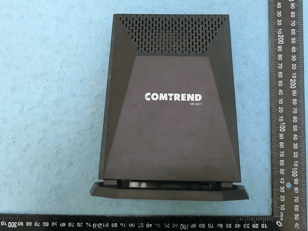
L9VVR3071
Jan 21, 2020Home Gateway
Equipment Class
DTS - Digital Transmission System