L9VWAP5903AC1200 Dual Band WiFi Mesh Extender
Comtrend Corporation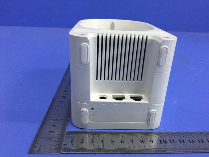
Click to zoom
Application Details
- Equipment Class
- DTS - Digital Transmission System
- Date of Grant
- Apr 29, 2020
- Application Purpose
- Original Equipment
- Date of Application
- Apr 20, 2020
- Equipment Note
- AC1200 Dual Band WiFi Mesh Extender
- Frequency Range
- 2412.00000000 - 2462.00000000
- Company
- Comtrend Corporation
- Country
- Taiwan
Documents & Files
Document Text
Text extracted from the exhibit documents filed with the FCC. Open a document above to read the original.
Users Manual
261072-045 Version A1.0, December 3, 2019 WAP-5903 AC1200 Dual Band WiFi Mesh Extender User Manual 1 Preface This manual provides information related to the installation and operation of this device. The individual reading this manual is presumed to have a basic understanding of telecommunications terminology and concepts. If you find the product to be inoperable or malfunctioning, please contact technical support for immediate service by email at [email protected] For product update, new product release, manual revision, or software upgrades, please visit our website at http://www.comtrend.com EU Liaison Office : COMTREND CORPORATION / Fijenhof 2, 5662AE Eindhoven, The Netherlands Comtrend Central Europe, s.r.o. / nkovcova 1518/2, 170 00 Praha 7 Important Safety Instructions With reference to unpacking, installation, use, and maintenance of your electronic device, the following basic guidelines are recommended: Do not use or install this product near water, to avoid fire or shock hazard. For example, near a bathtub, kitchen sink or laundry tub, or near a swimming pool. Also, do not expose the equipment to rain or damp areas (e.g. a wet basement). To safeguard the equipment against overheating, make sure that all openings in the unit that offer exposure to air are not blocked. Avoid using a telephone (other than a cordless type) during an electrical storm. There may be a remote risk of electric shock from lightening. Also, do not use the telephone to report a gas leak in the vicinity of the leak. CAUTION: Changes or modifications to this unit not expressly approved by the party responsible for compliance could void the user authority to operate the equipment. Do not stack equipment or place equipment in tight spaces, in drawers, or on carpets. Be sure that your equipment is surrounded by at least 2 inches of air space. If you experience trouble with this equipment, disconnect it from the network until the problem has been corrected or until you are sure that equipment is not malfunctioning. WARNING For indoor user only Do NOT open the casing Do NOT use near water Keep away from the fire For use in ventilated environment / space ATTENTION Cet appareil est conçu pour l'usage intérieur seulement N'ouvrez pas le boîtier N'utilisez pas cet appareil près de l'eau N'approchez pas du feu Veuillez utiliser dans un environnement aéré Power Specifications ( Alimentation): I/P: 100-240Vac, 50/60Hz, 0.6A 2 User Information Any changes or modifications not expressly approved by the party responsible for compliance could void your authority to operate the equipment. Aucune modification apportée à l’appareil par l’utilisateur, quelle qu’en soit la nature. Tout changement ou modification peuvent annuler le droit d’utilisation de l’appareil par l’utilisateur. Note: This equipment has been tested and found to comply with the limits for a Class B digital device, pursuant to part 15 of the FCC Rules. These limits are designed to provide reasonable protection against harmful interference in a residential installation. This equipment generates, uses and can radiate radio frequency energy and, if not installed and used in accordance with the instructions, may cause harmful interference to radio communications. However, there is no guarantee that interference will not occur in a particular installation. If this equipment does cause harmful interference to radio or television reception, which can be determined by turning the equipment off and on, the user is encouraged to try to correct the interference by one or more of the following measures: —Reorient or relocate the receiving antenna. —Increase the separation between the equipment and receiver. —Connect the equipment into an outlet on a circuit different from that to which the receiver is connected. —Consult the dealer or an experienced radio/TV technician for help. This device complies with Part 15 of the FCC Rules. Operation is subject to the following two conditions: (1) This device may not cause harmful interference, and (2) this device must accept any interference received, including interference that may cause undesired operation. This Class B digital apparatus complies with Canadian ICES-003. To reduce potential radio interference to other users, the antenna type and its gain should be so chosen that the equivalent isotropically radiated power (e.i.r.p.) is not more than that permitted for successful communication. This device complies with Part 15 of the FCC Rules and Industry Canada licence-exempt RSS standard(s). Operation is subject to the following two conditions: 1. This device may not cause interference, and 2. This device must accept any interference, including interference that may cause undesired operation of the device. Cet appareil numérique de la classe B est conforme à la norme NMB-003 Canada. Pour réduire le risque d’interférence aux autres utilisateurs, le type d’antenne et son gain doivent être choisies de façon que la puissance isotrope rayonnée équivalente (PIRE) ne dépasse pas ce qui est nécessaire pour une communication réussie. Cet appareil est conforme à la norme RSS Industrie Canada exempts de licence norme(s). Son fonctionnement est soumis aux deux conditions suivantes: 1. Cet appareil ne peut pas provoquer d’interférences et 2. Cet appareil doit accepter toute interférence, y compris les interférences qui peuvent causer un mauvais fonctionnement du dispositif. Radiation Exposure FCC 1. This Transmitter must not be co‐located or operating in conjunction with any other antenna or transmitter. 3 2. This equipment complies with FCC RF radiation exposure limits set forth for an uncontrolled environment. This equipment should be installed and operated with a minimum distance of 25 cm between the radiator and your body. ISED This device complies with the ISED radiation exposure limit set forth for an uncontrolled environment. This device should be installed and operated with minimum distance 25 …
Text truncated - open the document above for the full version.
Cover Letter(s)
COMTREND Corporation UNII Device Declaration Letter To whom it may concern: We have declared below featured for FCC/IC equipment authorization, Device FCC ID: L9VWAP5903; IC: 4013A-WAP5903 (1) DFS Device: Master Client with Radar detection capability N/A Client without radar detection capability, (2) Active / Passive Scanning , adhoc mode access point capability Frequency Band (MHz) Active Scanning (the device can transmit a probe (beacon)) passive scanning (where the device is can listen only with no probes) Ad Hoc Mode capability Access point capability 2412-2462 Yes No Yes No Yes No Yes No 5180-5240 Yes No Yes No Yes No Yes No 5260-5320 Yes No Yes No Yes No Yes No 5500-5720 Yes No Yes No Yes No Yes No 5745-5825 Yes No Yes No Yes No Yes No (3) Country code selection ability Yes No If yes, pls explain how it was implemented: (4) Meet 15.202 requirement Yes No pls check below : A master device is defined as a device operating in a mode in which it has the capability to transmit without receiving an enabling signal. In this mode it is able to select a channel and initiate a network by sending enabling signals to other devices A client device is defined as a device operating in a mode in which the transmissions of the device are under control of the master. A device in client mode is not able to initiate a network. (5) For client devices that have software configuration control to operate in different modes (active scanning in some and passive scanning in others) in different bands (devices with multiple equipment classes or those that operate on non-DFS frequencies) or modular devices which configure the modes of operations through software, the application must provide software and operations description on how the software and / or hardware is implemented to ensure that proper operations modes cannot be modified by end user or an installer. Apply Does not apply (If apply, pls help to provide explanation on it was implement, and how software was controlled) Should you have any questions or comments regarding this matter, please have my best attention. Sincerely, COMTREND Corporation <Signature of Bill Wang > ----------------------------------------------------------------------------------- Bill Wang (Manager) Email: [email protected]
Cover Letter(s)
RF_160, Issue 04 Shenzhen Toby Technology Co., Ltd. Declaration of Authorization We Name: Shenzhen Toby Technology Co., Ltd. Address: 1A/F., Bldg.6, Yusheng Industrial Zone, The National Road No.107, City: Shenzhen Country: China Declare that: Name Representative of agent: Ray Lai Agent Company name: Shenzhen Toby Technology Co., Ltd. Address: 1A/F., Bldg.6, Yusheng Industrial Zone, The National Road No.107, City: Shenzhen Country: China is authorized to apply for Certification of the following product(s): Product description: AC1200 Dual Band WiFi Mesh Extender Type designation: WAP-5903 Trademark: COMTREND Validity/ expiry date on our behalf. Date: 2020-03-25 City: Shenzhen Name: Ray Lai (2) Function: Manager Signature: Notes: (1): Required for FCC application (2): For FCC it must be the Grantee Code “owner” or the authorized agent.
Cover Letter(s)
FCC, Request for non-disclosure Date: 21-Nov-2018 RF_501, Issue 8 Page 1 of 1 Company Name: COMTREND Corporation Address: 3F-1, 10 Lane 609, Chung Hsin Road, Section 5, San Chung Dist, City: New Taipei City Country: Taiwan 24159 To: Telefication B.V., Dept. FCC TCB Edisonstraat 12A 6902 PK ZEVENAAR The Netherlands Subject: Request for confidentiality FCC ID: L9VWAP5903 Reference number: ###### Dear FCC TCB, 1. Long-Term Confidentiality Pursuant to 47 CFR Section 0.459(a) & (b), we hereby requests non-disclosure and confidential treatment of the following materials submitted in support of FCC certification application: Bill(s) of Material Block Diagrams Operational Description Schematic Diagrams Tune-up Procedure Above materials contain secrets, proprietary and technical information, which would customarily be guarded from competitors under 47 CFR, section 0.457(d)(2). Disclosure or publication or any portion of this company confidential material to other parties could cause substantial competitive harm and provide unjustified benefits for competitors. 2. Short-Term Confidentiality (STC) Pursuant to Public Notice DA 04-1705 of the Commission’s policy, in order to comply with the marketing regulations in 47 CFR §2.803 and the importation rules in 47 CFR §2.1204, applicant hereby requests Short-Term Confidential treatment of the following materials (See notes below): Internal Photos User’s Manual Test Set-up Photos External Photos Justification: Date: 2020-03-25 Name and signature of applicant: Bill Wang Notes: 1) A document or type of document can only have ONE type of confidentiality! 2) Short-Term confidentiality is in principle for 45 days from date of grant; it can be extended max 3 times (total time 180 days max.)! The planned date should stated in the RF731 application form. 3) FCC must be informed when marketing begins earlier. 4) Release takes place automatically thus extension must be requested in time. Telefication does not remind you of this! 5) Request for extension or for release must be received by Telefication at least 7 days before date of actual marketing or before expiration of the STC period
Cover Letter(s)
COMTREND Corporation 3F-1, 10 Lane 609, Chung Hsin Road, Section 5, San Chung Dist, New Taipei City, Taiwan 24159 TPC Declaration FCC ID: L9VWAP5903 To whom it may concern: We, COMTREND Corporation , declare that the device supports the TPC function in final F/W, when this product is sold to FCC market. Regards, Sincerely yours, Applicant: COMTREND Corporation Address: 3F-1, 10 Lane 609, Chung Hsin Road, Section 5, San Chung Dist, New Taipei City, Taiwan 24159 Signature: Date: 2020 / 3 / 25 Print name: Bill.Wang Email: [email protected] Tel: +886-2-2999-8261
External Photos
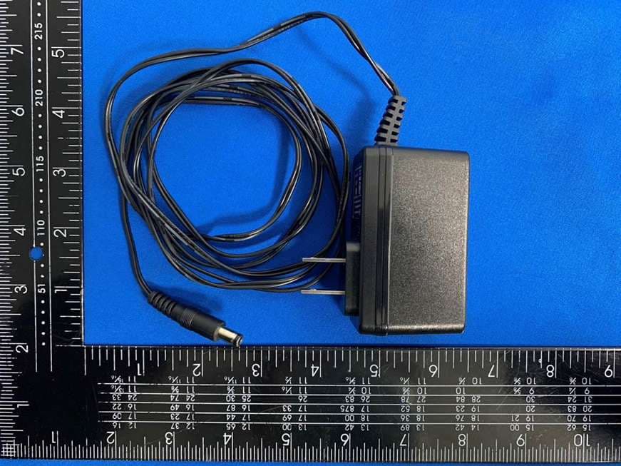
Report No.: TB-FCC171063 Page: 3 of 18 FCC ID: L9VWAP5903 TB-RF-074-1.0 Appendix III EUT External Photographs Photo 1 Appearance of EUT Photo 2 Appearance of EUT Report No.: TB-FCC171063 Page: 4 of 18 FCC ID: L9VWAP5903 TB-RF-074-1.0 Photo 3 Appearance of EUT Photo 4 Appearance of EUT Report No.: TB-FCC171063 Page: 5 of 18 FCC ID: L9VWAP5903 TB-RF-074-1.0 Photo 5 Appearance of EUT Photo 6 Appearance of EUT Report No.: TB-FCC171063 Page: 6 of 18 FCC ID: L9VWAP5903 TB-RF-074-1.0 Photo 7 Appearance of EUT Photo 8 Appearance of Adapter Report No.: TB-FCC171063 Page: 7 of 18 FCC ID: L9VWAP5903 TB-RF-074-1.0 Photo 9 Appearance of Adapter
ID Label/Location Info
Report No.: TB-FCC171063 Page: 2 of 18 FCC ID: L9VWAP5903 TB-RF-074-1.0 Appendix II ID Label Location ID LOCATION
ID Label/Location Info
Report No.: TB-FCC171063 Page: 1 of 18 FCC ID: L9VWAP5903 TB-RF-074-1.0 Appendix IFCC ID Label Size for the label: 97.7mm X 14.9mm
Internal Photos
Report No.: TB-FCC171063 Page: 10 of 18 FCC ID: L9VWAP5903 TB-RF-074-1.0 Photo 14 Appearance of PCB Photo 15 Appearance of PCB Report No.: TB-FCC171063 Page: 11 of 18 FCC ID: L9VWAP5903 TB-RF-074-1.0 Photo 16 Appearance of PCB Photo 17 Appearance of PCB Report No.: TB-FCC171063 Page: 12 of 18 FCC ID: L9VWAP5903 TB-RF-074-1.0 Photo 18 Appearance of PCB Photo 19 Appearance of PCB Report No.: TB-FCC171063 Page: 13 of 18 FCC ID: L9VWAP5903 TB-RF-074-1.0 Photo 20 Appearance of PCB Photo 21 Appearance of PCB Report No.: TB-FCC171063 Page: 14 of 18 FCC ID: L9VWAP5903 TB-RF-074-1.0 Photo 22 Appearance of Antenna
RF Exposure Info
Shenzhen Toby Technology Co., Ltd. Report No.: TB-MPE171066 Page: 1 of 9 TB-RF-075-1.0 1A/F., Bldg.6, Yusheng Industrial Zone, The National Road No.107 Xixiang Section 467, Xixiang, Bao’an, Shenzhen, China Tel: +86 75526509301 Fax: +86 75526509195 Maximum Permissible Exposure Evaluation FCC ID: L9VWAP5903 1. Client Information Applicant : COMTREND Corporation Address : 3F-1, 10 Lane 609, Chung Hsin Road, Section 5, San Chung Dist, New Taipei City, Taiwan 24159 Manufacturer : COMTREND Corporation Address : 3F-1, 10 Lane 609, Chung Hsin Road, Section 5, San Chung Dist, New Taipei City, Taiwan 24159 Factory : Shenzhen COMNECT Technology Co., Ltd. Address : G Zone, 3/F, Building 1, Baisha High-Tech Park, No. 3011, Shahe Road West, XiLi Street, Nanshan District, Shenzhen, China 2. General Description of EUT EUT Name : AC1200 Dual Band WiFi Mesh Extender Models No. : WAP-5903 S/N Number: : M1914000765, M1914000766 Brand Name : COMTREND Product Description : Operation Frequency: 802.11b/g/n(HT20): 2412MHz~2462MHz 802.11n(HT40): 2422MHz~2452MHz U-NII-1: 5180MHz~5240MHz, U-NII-2A: 5260MHz~5320MHz U-NII-2C: 5500MHz~5720MHz U-NII-3: 5745MHz~5825MHz Power Rating : Adapter(RD1201500-C55-153MG): Input: AC 100-240V, 50/60Hz, 0.6A max Output: DC 12V, 1.5A Software Version : BS51-3411DCTU-C01_R03 Hardware Version : AR-M400 V3.0 Connecting I/O Port(S) : Please refer to the User's Manual Remark : the MPE report used the EUT-2(S/N number: M1914000766). Report No.: TB-MPE171066 Page: 2 of 9 TB-RF-075-1.0 MPE Calculations 1. Antenna Gain: Antenna Brand Model Name Type 2.4G Antenna Gain(dBi) ANT. A N/A SLEingB400150135 copper tube5.05 ANT. B N/A SLEingB400150135 copper tube5.05 Note: For MIMO mode: Directional Gain=ANT. Gain+10*LOG(N ANT ) =8.06 dBi 2.4G working with 802.11g/n(HT20/HT40) has MIMO mode. the 802.11 b Mode only use Ant. A Antenna Brand Model Name Type Antenna Gain (dBi) Directional Gain (dBi) ANT. A N/A SLEingB400150135 copper tube U-NII-1: 5.42 U-NII-1: 8.43 U-NII-2A: 8.24 U-NII-2C: 8.04 U-NII-3: 8.10 U-NII-2A: 5.23 U-NII-2C: 5.03 U-NII-3: 5.09 ANT. B N/A SLEingB400150135 copper tube U-NII-1: 5.42 U-NII-2A: 5.23 U-NII-2C: 5.03 U-NII-3: 5.09 Note: For MIMO mode: Directional Gain=ANT. Gain+10*LOG(N ANT ). 2. EUT Operation Condition: Software provided by client enabled the EUT to transmit and receive data at lowest, middle and highest channel individually. 3. Exposure Evaluation: Equation from page 18 of OET Bulletin 65, Edition 97-01 S=(PG)/4πR 2 Where S: power density P: power input to the antenna G: power gain of the antenna in the direction of interest relative to an isotropic radiator. R: distance to the center of radiation of the antenna 4. Simultaneous transmission MPE Considerations According to KDB447498 :All transmitters and antennas in the host must be either evaluated for MPE compliance, by measurement or computational modeling, or qualify for the standalone MPE test exclusion in section 7.1.Simultaneous transmission MPE test exclusion applies when the sum of the MPE ratios for all simultaneous transmitting antennas incorporated in a host device, based on the calculated/estimated, numerically modeled or measured field strengths or power density, is ≤ 1.0. This means that: ∑ of MPE ratios ≤ 1.0 Report No.: TB-MPE171066 Page: 3 of 9 TB-RF-075-1.0 5. Standalone MPE Evaluation: [2.4GHz WLAN] Mode Channel Frequency Peak Conducted Output Power (dBm) Tolerance ± (dB) Turn-up Power Tolerance (dB) Ant.A Ant.B Ant.A Ant.B IEEE 802.11b 1 2412 28.93 / 1.0 28±1 / 6 2437 27.89 / 1.0 28±1 / 11 2462 27.39 / 1.0 28±1 / IEEE 802.11g 1 2412 24.46 24.47 1.0 24±1 24±1 6 2437 24.26 24.39 1.0 24±1 24±1 11 2462 24.52 24.50 1.0 24±1 24±1 IEEE 802.11n HT20 1 2412 24.64 24.51 1.0 24±1 24±1 6 2437 24.34 24.41 1.0 24±1 24±1 11 2462 24.58 24.45 1.0 24±1 24±1 IEEE 802.11n HT40 3 2422 24.58 24.32 1.0 24±1 24±1 6 2437 24.43 24.49 1.0 24±1 24±1 9 2452 24.42 24.26 1.0 24±1 24±1 [5GHz WLAN U-NII-1] Mode Channel Frequency Peak Conducted Output Power (dBm) Tolerance ± (dB) Turn-up Power Tolerance (dB) Ant.A Ant.B Ant.A Ant.B IEEE 802.11a 36 5180 18.96 18.49 1.0 18±1 18±1 40 5200 18.90 18.69 1.0 18±1 18±1 48 5240 19.15 18.93 1.0 19±1 19±1 IEEE 802.11n HT20 36 5180 18.86 19.41 1.0 19±1 19±1 40 5200 19.03 19.44 1.0 19±1 19±1 48 5240 19.52 19.36 1.0 19±1 19±1 IEEE 802.11ac VHT20 36 5180 19.39 19.84 1.0 19±1 19±1 40 5200 19.52 19.41 1.0 19±1 19±1 48 5240 19.95 19.22 1.0 19±1 19±1 IEEE 802.11n HT40 38 5190 22.17 22.51 1.0 22±1 22±1 46 5230 22.56 22.10 1.0 22±1 22±1 IEEE 802.11ac VHT40 38 5190 22.27 22.49 1.0 22±1 22±1 46 5230 22.59 22.08 1.0 22±1 22±1 IEEE 802.11ac VHT80 42 5210 21.69 21.42 1.0 22±1 22±1 Report No.: TB-MPE171066 Page: 4 of 9 TB-RF-075-1.0 [5GHz WLAN U-NII-2A] Mode Channel Frequency Peak Conducted Output Power (dBm) Tolerance ± (dB) Turn-up Power Tolerance (dB) Ant.A Ant.B Ant.A Ant.B IEEE 802.11a 52 5260 13.14 12.89 1.0 13±1 13±1 56 5300 13.13 13.27 1.0 13±1 13±1 64 5320 13.20 13.19 1.0 13±1 13±1 IEEE 802.11n HT20 52 5260 13.86 13.19 1.0 13±1 13±1 56 5300 13.24 13.72 1.0 13±1 13±1 64 5320 13.63 13.68 1.0 13±1 13±1 IEEE 802.11ac VHT20 52 5260 13.81 13.55 1.0 13±1 13±1 56 5300 13.19 13.79 1.0 13±1 13±1 64 5320 13.48 13.76 1.0 13±1 13±1 IEEE 802.11n HT40 54 5270 16.61 16.47 1.0 17±1 17±1 62 5310 16.40 16.77 1.0 17±1 17±1 IEEE 802.11ac VHT40 54 5270 16.97 16.39 1.0 17±1 17±1 62 5310 17.08 16.32 1.0 17±1 17±1 IEEE 802.11ac VHT80 58 5290 18.32 18.11 1.0 18±1 18±1 [5GHz WLAN U-NII-2C] Mode Channel Frequency Peak Conducted Output Power (dBm) Tolerance ± (dB) Turn-up Power Tolerance (dB) Ant.A Ant.B Ant.A Ant.B IEEE 802.11a 100 5500 12.97 13.00 1.0 13±1 13±1 124 5600 13.45 13.02 1.0 13±1 13±1 144 5720 12.78 12.40 1.0 13±1 13±1 IEEE 802.11n HT20 100 5500 13.21 13.27 1.0 13±1 13±1 124 5600 13.32 13.69 1.0 13±1 13±1 144 5720 13.16 13.69 1.0 13±1 13±1 IEEE 802.11ac VHT20 100 5500 12.90 12.81 1.0 13±1 13±1 124 5600 13.26 12.89 1.0 13±1 13±1 144 5720 13.21 13.02 1.0 13±1 13±1 IEEE 802.11n HT40 102 5510 16.76 16.61 1.0 16±1 16±1…
Text truncated - open the document above for the full version.
Test Report
Shenzhen Toby Technology Co., Ltd. Report No.: TB-FCC171063 Page: 1 of 121 TB-RF-074-1.0 1A/F., Bldg.6, Yusheng Industrial Zone, The National Road No.107 Xixiang Section 467, Xixiang, Bao’an, Shenzhen, China Tel: +86 75526509301 Fax: +86 75526509195 FCC Radio Test Report FCC ID: L9VWAP5903 Original Grant Report No. : TB-FCC171063 Applicant : COMTREND Corporation Equipment Under Test (EUT) EUT Name : AC1200 Dual Band WiFi Mesh Extender Model No. : WAP-5903 Series Model No. : N/A S/N Number: : M1914000765, M1914000766 Brand Name : COMTREND Receipt Date : 2019-12-05 Test Date : 2019-12-07 to 2020-03-24 Issue Date : 2020-03-25 Standards : FCC Part 15, Subpart C 15.247 Test Method : ANSI C63.10: 2013 Conclusions : PASS In the configuration tested, the EUT complied with the standards specified above, The EUT technically complies with the FCC and IC requirements Test/Witness Engineer : Jack Deng Test/Witness Engineer : Ivan Su Approved& Authorized : Benny Xu This report details the results of the testing carried out on one sample. The results contained in this test report do not relate to other samples of the same product. The manufacturer should ensure that all products in series production are in conformity with the product sample detailed in the report. Report No.: TB-FCC171063 Page: 2 of 121 TB-RF-074-1.0 Contents CONTENTS ............................................................................................................................................. 2 1. GENERAL INFORMATION ABOUT EUT ............................................................................. 5 1.1 Client Information ................................................................................................................. 5 1.2 General Description of EUT (Equipment Under Test) ................................................... 5 1.3 Block Diagram Showing the Configuration of System Tested ...................................... 7 1.4 Description of Support Units .............................................................................................. 7 1.5 Description of Test Mode .................................................................................................... 8 1.6 Description of Test Software Setting ................................................................................ 9 1.7 Measurement Uncertainty ................................................................................................ 10 1.8 Test Facility ......................................................................................................................... 10 2. TEST SUMMARY ..................................................................................................................... 11 3. TEST SOFTWARE ................................................................................................................... 11 4. TEST EQUIPMENT .................................................................................................................. 12 5. CONDUCTED EMISSION TEST ........................................................................................... 13 5.1 Test Standard and Limit .................................................................................................... 13 5.2 Test Setup ........................................................................................................................... 13 5.3 Test Procedure ................................................................................................................... 14 5.4 Deviation From Test Standard ......................................................................................... 14 5.5 EUT Operating Mode ........................................................................................................ 14 5.6 Test Data ............................................................................................................................. 14 6. RADIATED EMISSION TEST ................................................................................................ 15 6.1 Test Standard and Limit .................................................................................................... 15 6.2 Test Setup ........................................................................................................................... 16 6.3 Test Procedure ................................................................................................................... 17 6.4 Deviation From Test Standard ......................................................................................... 18 6.5 EUT Operating Condition ................................................................................................. 18 6.6 Test Data ............................................................................................................................. 18 7. RESTRICTED BANDS REQUIREMENT ............................................................................. 19 7.1 Test Standard and Limit .................................................................................................... 19 7.2 Test Setup ........................................................................................................................... 19 7.3 Test Procedure ................................................................................................................... 20 7.4 Deviation From Test Standard ......................................................................................... 20 7.5 EUT Operating Condition ................................................................................................. 20 7.6 Test Data ............................................................................................................................. 20 8. BANDWIDTH TEST ................................................................................................................. 21 8.1 Test Standard and Limit ..............................…
Text truncated - open the document above for the full version.
Test Report
Report No.: TB-FCC171063 Page: 96 of 121 TB-RF-074-1.0 Attachment D-- Bandwidth Test Data Temperature: 25°C Relative Humidity: 55% Test Voltage: AC 120V/60HZ Test Mode: TX 802.11B Mode ANT. A Channel frequency (MHz) 6dB Bandwidth (MHz) 99% Bandwidth (MHz) Limit (MHz) 2412 9.132 14.558 >=0.5 2437 9.328 14.633 2462 9.152 14.738 802.11B Mode 2412 MHz Report No.: TB-FCC171063 Page: 97 of 121 TB-RF-074-1.0 802.11B Mode 2437 MHz 802.11B Mode 2462 MHz Report No.: TB-FCC171063 Page: 98 of 121 TB-RF-074-1.0 Temperature: 25°C Relative Humidity: 55% Test Voltage: AC 120V/60HZ Test Mode: TX 802.11G Mode ANT. A Channel frequency (MHz) 6dB Bandwidth (MHz) 99% Bandwidth (MHz) Limit (MHz) 2412 16.42 16.350 >=0.5 2437 16.42 16.349 2462 16.40 16.336 802.11G Mode 2412 MHz Report No.: TB-FCC171063 Page: 99 of 121 TB-RF-074-1.0 802.11G Mode 2437 MHz 802.11G Mode 2462 MHz Report No.: TB-FCC171063 Page: 100 of 121 TB-RF-074-1.0 Temperature: 25°C Relative Humidity: 55% Test Voltage: AC 120V/60HZ Test Mode: TX 802.11G Mode ANT. B Channel frequency (MHz) 6dB Bandwidth (MHz) 99% Bandwidth (MHz) Limit (MHz) 2412 16.42 16.350 >=0.5 2437 16.43 16.352 2462 16.40 16.337 802.11G Mode 2412 MHz Report No.: TB-FCC171063 Page: 101 of 121 TB-RF-074-1.0 802.11G Mode 2437 MHz 802.11G Mode 2462 MHz Report No.: TB-FCC171063 Page: 102 of 121 TB-RF-074-1.0 Temperature: 25°C Relative Humidity: 55% Test Voltage: AC 120V/60HZ Test Mode: TX 802.11N(HT20) Mode ANT. A Channel frequency (MHz) 6dB Bandwidth (MHz) 99% Bandwidth (MHz) Limit (MHz) 2412 17.35 17.442 >=0.5 2437 17.45 17.439 2462 17.55 17.437 802.11N(HT20) Mode 2412 MHz Report No.: TB-FCC171063 Page: 103 of 121 TB-RF-074-1.0 802.11N(HT20) Mode 2437 MHz 802.11N(HT20) Mode 2462 MHz Report No.: TB-FCC171063 Page: 104 of 121 TB-RF-074-1.0 Temperature: 25°C Relative Humidity: 55% Test Voltage: AC 120V/60HZ Test Mode: TX 802.11N(HT20) Mode ANT. B Channel frequency (MHz) 6dB Bandwidth (MHz) 99% Bandwidth (MHz) Limit (MHz) 2412 17.34 17.440 >=0.5 2437 17.55 17.436 2462 17.55 17.436 802.11N(HT20) Mode 2412 MHz Report No.: TB-FCC171063 Page: 105 of 121 TB-RF-074-1.0 802.11N(HT20) Mode 2437 MHz 802.11N(HT20) Mode 2462 MHz Report No.: TB-FCC171063 Page: 106 of 121 TB-RF-074-1.0 Temperature: 25°C Relative Humidity: 55% Test Voltage: AC 120V/60HZ Test Mode: TX 802.11N(HT40) Mode ANT. A Channel frequency (MHz) 6dB Bandwidth (MHz) 99% Bandwidth (MHz) Limit (MHz) 2422 35.93 35.626 >=0.5 2437 35.92 35.606 2452 35.93 35.618 802.11N(HT40) Mode 2422 MHz Report No.: TB-FCC171063 Page: 107 of 121 TB-RF-074-1.0 802.11N(HT40) Mode 2437 MHz 802.11N(HT40) Mode 2452 MHz Report No.: TB-FCC171063 Page: 108 of 121 TB-RF-074-1.0 Temperature: 25°C Relative Humidity: 55% Test Voltage: AC 120V/60HZ Test Mode: TX 802.11N(HT40) Mode ANT. B Channel frequency (MHz) 6dB Bandwidth (MHz) 99% Bandwidth (MHz) Limit (MHz) 2422 35.54 35.629 >=0.5 2437 35.68 35.611 2452 35.94 35.617 802.11N(HT40) Mode 2422 MHz Report No.: TB-FCC171063 Page: 109 of 121 TB-RF-074-1.0 802.11N(HT40) Mode 2437 MHz 802.11N(HT40) Mode 2452 MHz Report No.: TB-FCC171063 Page: 110 of 121 TB-RF-074-1.0 Attachment E-- Peak Output Power Test Data Conducted Power 802.11b Power Channel Frequency Conducted Power (dBm) Max. Limit (dBm) Ant. A 1 2412 MHz 28.93 30 6 2437 MHz 27.89 11 2462 MHz 27.39 802.11g Power Channel Frequency Conducted Power (dBm) Max. Limit (dBm) ANT. A. ANT. B Total 1 2412 MHz 24.46 24.47 27.38 27.94 6 2437 MHz 24.26 24.39 27.34 11 2462 MHz 24.52 24.50 27.52 802.11n(HT20) Power Channel Frequency Conducted Power (dBm) Max. Limit (dBm) ANT. A. ANT. B Total 1 2412 MHz 24.64 24.51 27.59 27.94 6 2437 MHz 24.34 24.41 27.39 11 2462 MHz 24.58 24.45 27.53 802.11n(HT40) Power Channel Frequency Conducted Power (dBm) Max. Limit (dBm) ANT. A. ANT. B Total 3 2422 MHz 24.58 24.32 27.46 27.94 6 2437 MHz 24.43 24.49 27.47 9 2452 MHz 24.42 24.26 27.35 Note: The ANT. A. and ANT. B will transmitting simultaneously for the 802.11g/n(HT20)/n(HT40) Mode, the T Directional Gain =Ant. Gain + 10*LOG(N ANT ) =8.06 dBi>6 dBi. So P out = P limit -(G TX -6)]=30-2.06=27.94dBm Report No.: TB-FCC171063 Page: 111 of 121 TB-RF-074-1.0 Duty Cycle Mode Channel frequency (MHz) Test Result 802.11b 2412 >98% 2437 2462 802.11g 2412 2437 2462 802.11n (HT20) 2412 2437 2462 802.11n (HT40) 2422 2437 2452 Please see below plots Report No.: TB-FCC171063 Page: 112 of 121 TB-RF-074-1.0 802.11 B Mode 2437 MHz 802.11 G Mode 2437 MHz Report No.: TB-FCC171063 Page: 113 of 121 TB-RF-074-1.0 802.11 N(HT20) Mode 2437 MHz 802.11 N(HT40) Mode 2437 MHz Report No.: TB-FCC171063 Page: 114 of 121 TB-RF-074-1.0 Attachment F-- Power Spectral Density Test Data 802.11b Mode Channel Frequency Con…
Text truncated - open the document above for the full version.
Contact Information
Applicant
Bill Wang
Technical Contact
Shenzhen Toby Technology Co., Ltd.Ivan su
[email protected]755-26509301
1A/F., Bldg.6, Yusheng Industrial Zone, · Shenzhen · China
Non-Technical Contact
Shenzhen Toby Technology Co., Ltd.Ivan su
[email protected]755-26509301
Test Firm
Shenzhen Toby Technology Co., Ltd.Ray Lai
Technical Specifications
| # | Rule Parts | Frequency Range | Power Output |
|---|---|---|---|
| 1 | 15C | 2.41 GHz - 2.46 GHz | 780.00 mW |
Other Applications from Comtrend Corporation
L9VVR3071V2
Nov 30, 2023Home Gateway
Equipment Class
DTS - Digital Transmission System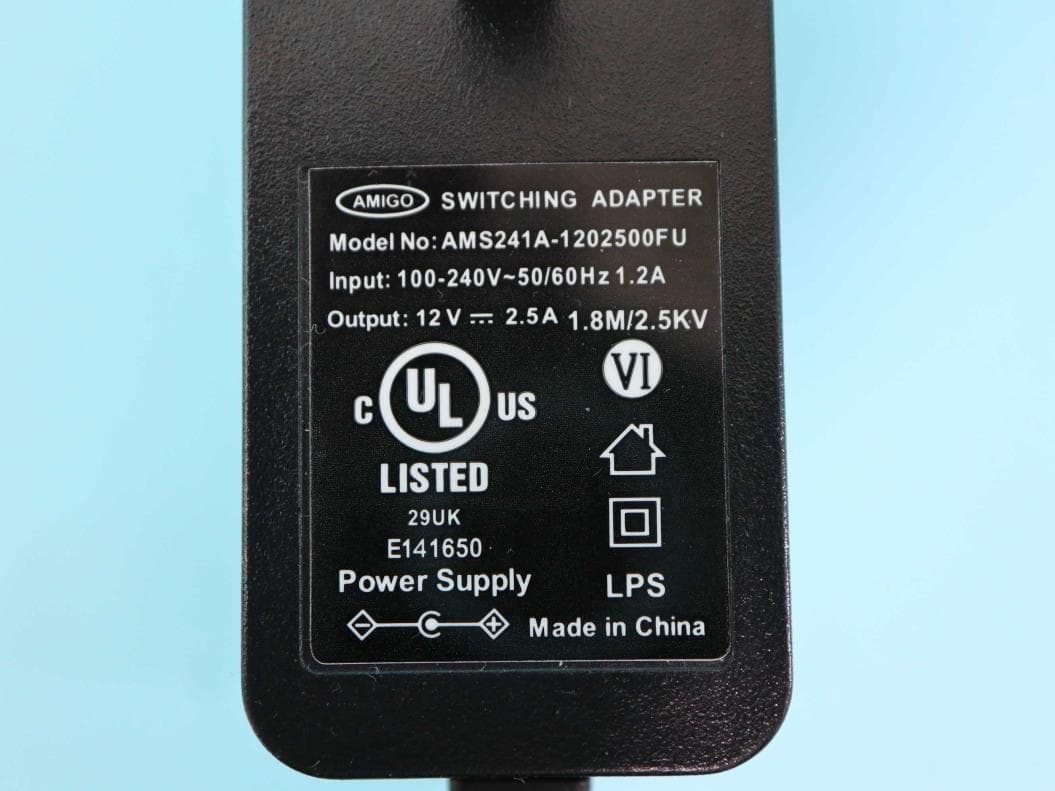
L9VPRT6351
Jul 04, 2023Home Gateway
Equipment Class
DTS - Digital Transmission System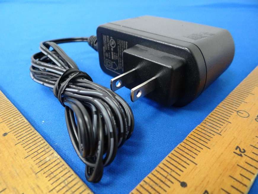
L9VWAP60AXD
Jun 07, 2022Home Gateway
Equipment Class
DTS - Digital Transmission System
L9VVR3071
Jan 21, 2020Home Gateway
Equipment Class
DTS - Digital Transmission System
L9VPG-9142S
Jan 28, 2015Powerline Ethernet Adapter with WiFi
Equipment Class
DTS - Digital Transmission System