L9VPRT6351Home Gateway
Comtrend Corporation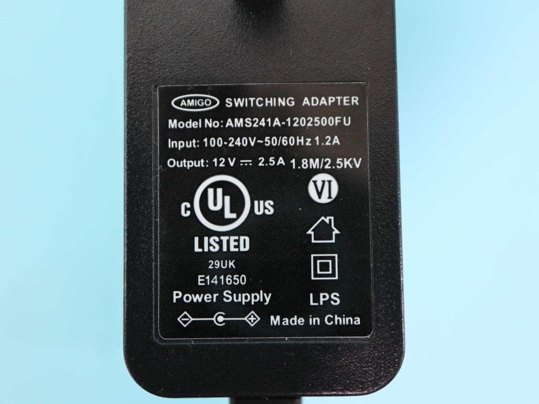
Click to zoom
Application Details
- Equipment Class
- DTS - Digital Transmission System
- Date of Grant
- Jul 04, 2023
- Application Purpose
- Original Equipment
- Date of Application
- Jun 14, 2023
- Equipment Note
- Home Gateway
- Frequency Range
- 2412.00000000 - 2462.00000000
- Company
- Comtrend Corporation
- Country
- Taiwan
Documents & Files
Document Text
Text extracted from the exhibit documents filed with the FCC. Open a document above to read the original.
Users Manual
261097-037 PRT-6351 ( WR-2412u ) Home Gateway User Manual Version A1.0 May 16, 2023 1 Preface This manual provides information related to the installation and operation of this device. The individual reading this manual is presumed to have a basic understanding of telecommunications terminology and concepts. If you find the product to be inoperable or malfunctioning, please contact technical support for immediate service by email at [email protected] For product update, new product release, manual revision, or software upgrades, please visit our website at http://www.comtrend.com MPORTANT SAFETY INSTRUCTIONS When using your telephone equipment (for unpacking, installation, use, and maintenance), basic safety precautions should always be followed to reduce the risk of fire, electric shock and injury to persons, including the following: Do not use this product near water for example, near a bathtub, washbowl, kitchen sink or laundry tub, in a wet basement or near a swimming pool. Also, do not expose the equipment to rain or damp areas (e.g. a wet basement). Never install telephone wiring during stormy weather conditions. Avoid using a telephone (other than a cordless type) during an electrical storm there may be a remote risk of electric shock from lightning. Do not use the telephone to report a gas leak in the vicinity of the leak Use only the power cord and batteries (or adapter) indicated in this manual. Do not dispose of batteries in a fire. They may explode. Check with local codes for possible special disposal instructions Do not connect the power supply cord on elevated surfaces. Allow it to lie freely. There should be no obstructions in its path and no heavy items should be placed on the cord. In addition, do not walk on, step on, or mistreat the cord. SAVE THESE INSTRUCTIONS CAUTION: Always disconnect all telephone lines from the wall outlet before servicing or disassembling this equipment. Changes or modifications to this unit not expressly approved by the party responsible for compliance could void the user authority to operate the equipment. Do not stack equipment or place equipment in tight spaces, in drawers, or on carpets. Be sure that your equipment is surrounded by at least 2 2 inches of air space. To prevent interference with cordless phones, ensure that the gateway is at least 5 feet ( 1.5m )from the cordless phone base station. If you experience trouble with this equipment, disconnect it from the network until the problem has been corrected or until you are sure that equipment is not malfunctioning. WARNING Disconnect the power line from the device before servicing For indoor use only Do NOT open the casing Do NOT use near water Keep away from the fire For use in ventilated environment / space Débranchez l'alimentation électrique avant l'entretien Cet appareil est conçu pour l'usage intérieur seulement N'ouvrez pas le boîtier N'utilisez pas cet appareil près de l'eau N'approchez pas du feu Veuillez utiliser dans un environnement aéré Power Specifications ( Alimentation ) : Input : 12Vdc, 2.5A Output : USB 3.0, 900mA User Information Any changes or modifications not expressly approved by the party responsible for compliance could void your authority to operate the equipment. Aucune modification apportée à l’appareil par l’utilisateur, quelle qu’en soit la nature. Tout changement ou modification peuvent annuler le droit d’utilisation de l’appareil par l’utilisateur. Note: This equipment has been tested and found to comply with the limits for a Class B digital device, pursuant to part 15 of the FCC Rules. These limits are designed to provide reasonable protection against harmful interference in a residential installation. This equipment generates, uses and can radiate radio frequency energy and, if not installed and used in accordance with the instructions, may cause harmful interference to radio communications. However, there is no guarantee that interference will not occur in a particular installation. If this equipment does cause harmful interference to radio or television reception, which can be determined by turning the equipment off and on, the user is encouraged to try to correct the interference by one or more of the following measures: —Reorient or relocate the receiving antenna. —Increase the separation between the equipment and receiver. —Connect the equipment into an outlet on a circuit different from that to which the receiver is connected. —Consult the dealer or an experienced radio/TV technician for help. 3 This device complies with Part 15 of the FCC Rules. Operation is subject to the following two conditions: (1) This device may not cause harmful interference, and (2) this device must accept any interference received, including interference that may cause undesired operation. This Class B digital apparatus complies with Canadian ICES-003. To reduce potential radio interference to other users, the antenna type and its gain should be so chosen that the equivalent isotropically radiated power (e.i.r.p.) is not more than that permitted for successful communication. This device complies with Part 15 of the FCC Rules and Industry Canada licence- exempt RSS standard(s). Operation is subject to the following two conditions: 1. This device may not cause interference, and 2. This device must accept any interference, including interference that may cause undesired operation of the device. Cet appareil numérique de la classe B est conforme à la norme NMB-003 Canada. Pour réduire le risque d’interférence aux autres utilisateurs, le type d’antenne et son gain doivent être choisies de façon que la puissance isotrope rayonnée équivalente (PIRE) ne dépasse pas ce qui est nécessaire pour une communication réussie. Cet appareil est conforme à la norme RSS Industrie Canada exempts de licence norme(s). Son fonctionnement est soumis aux deux conditions suivantes: 1. Cet appareil ne peut pas provoquer d’interférences et 2. …
Text truncated - open the document above for the full version.
Users Manual
145 7.2 Ethernet OAM The Ethernet OAM (Operations, Administration, Management) page provides settings to enable/disable 802.3ah, 802.1ag/Y1.731 OAM protocols. To enable Ethernet Link OAM (802.3 ah), click Enabled to display the full configuration list. At least one option must be enabled for 802.1ah. Item Description WAN Interface Select layer 2 WAN interface for outgoing OAM packets OAM ID OAM Identification number Auto Event Supports OAM auto event Variable Retrieval Supports OAM variable retrieval Link Events Supports OAM link events Remote Loopback Supports OAM remove loopback 146 Active mode Supports OAM active mode To enable Ethernet Service OAM (802.1ag/Y1731), click Enabled to display the full configuration list. Click Apply/Save to implement new configuration settings. Item Description WAN Interface Select from the list of WAN Interfaces to send OAM packets MD Level Maintenance Domain Level MD Name Maintenance Domain name MA ID Maintenance Association Identifier Local MEP ID Local Maintenance association End Point Identifier Local MEP VLAN ID VLAN IP used for Local Maintenance End point 147 Click CCM Transmission to enable CPE sending Continuity Check Message (CCM) continuously. Remote MEP ID Maintenance association End Point Identifier for the remote receiver To perform Loopback/Linktrace OAM test, enter the Target MAC of the destination and click “Send Loopback” or “Send Linktrace” button. Target MAC MAC Address of the destination to send OAM loopback/linktrace packet Linktrace TTL Time to Live value for the loopback/linktrace packet 7.3 Uptime Status This page shows System, ETH and Layer 3 uptime. If the ETH or Layer 3 connection is down, the uptime will stop incrementing. If the service is restored, the counter will reset and start from 0. A Bridge interface will follow the ETH timer. The "ClearAll" button will restart the counters from 0 or show "Not Connected" if the interface is down. 148 7.4 Ping Input the IP address/hostname and click the Ping button to execute ping diagnostic test to send the ICMP request to the specified host. 149 7.5 Trace Route Input the IP address/hostname and click the TraceRoute button to execute the trace route diagnostic test to send the ICMP packets to the specified host. 150 Chapter 8 Management You can reach this page by clicking on the following icon located at the top of the screen. The Management menu has the following maintenance functions and processes: 8.1 Settings This includes Backup Settings, Update Settings, and Restore Default screens. 8.1.1 Backup Settings This option recovers configuration files previously saved using Backup Settings. Click the Choose File button to locate the backup file. Then click the Update Settings button to update your device settings. 151 8.1.2 Update Settings This option recovers configuration files previously saved using Backup Settings. Click the Choose File button to search for the file, then click Update Settings to recover settings. 8.1.3 Restore Default Click Restore Default Settings to restore factory default settings. After Restore Default Settings is clicked, the following screen appears. 152 Close the browser and wait for 2 minutes before reopening it. It may also be necessary, to reconfigure your PC IP configuration to match any new settings. NOTE: This entry has the same effect as the Reset button. The PRT-6351 board hardware and the boot loader support the reset to default. If the Reset button is continuously pressed for more than 10 seconds, the current configuration data will be erased. If the Reset button is continuously pressed for more than 60 seconds, the boot loader will erase all configuration data saved in flash memory and enter bootloader mode. 153 8.2 System Log This function allows a system log to be kept and viewed upon request. Follow the steps below to configure, enable, and view the system log. STEP 1: Click Configure System Log, as shown below (circled in Red). STEP 2: Select desired options and click Apply/Save. Consult the table below for detailed descriptions of each system log option. Item Description Log Indicates whether the system is currently recording events. The user can enable or disable event logging. By default, it is disabled. To enable it, select the Enable radio button and then 154 click Apply/Save. Log Level Allows you to configure the event level and filter out unwanted events below this level. The events ranging from the highest critical level “Emergency” down to this configured level will be recorded to the log buffer on the PRT-6351 SDRAM. When the log buffer is full, the newer event will wrap up to the top of the log buffer and overwrite the old event. By default, the log level is “Debugging”, which is the lowest critical level. The log levels are defined as follows: Emergency = system is unusable Alert = action must be taken immediately Critical = critical conditions Error = Error conditions Warning = normal but significant condition Notice= normal but insignificant condition Informational= provides information for reference Debugging = debug-level messages Emergency is the most serious event level, whereas Debugging is the least important. For instance, if the log level is set to Debugging, all the events from the lowest Debugging level to the most critical level Emergency level will be recorded. If the log level is set to Error, only Error and the level above will be logged. Display Level Allows the user to select the logged events and displays on the View System Log window for events of this level and above to the highest Emergency level. Mode Allows you to specify whether events should be stored in the local memory, or be sent to a remote system log server, or both simultaneously. If remote mode is selected, view system log will not be able to display events saved in the remote system log server. When either Remote mode or Both mode is configured, the WEB UI will prompt the user to enter the Server IP address and Server UDP port. ST…
Text truncated - open the document above for the full version.
External Photos
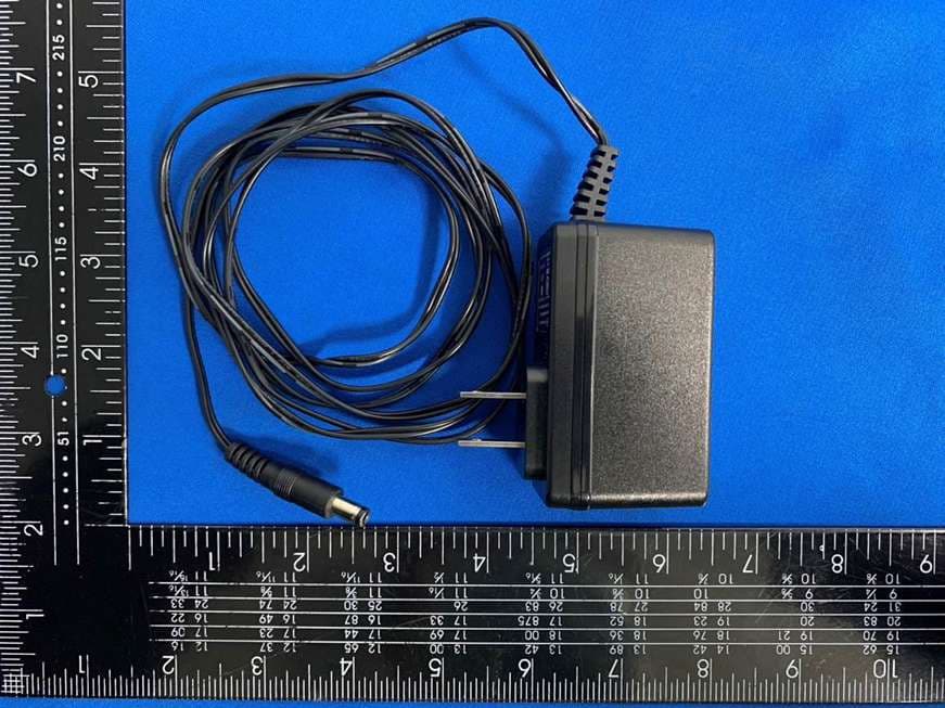
Photographs of EUT Report No. : EP310610 Sporton International Inc. Page No. : 1 of 28 Report Template No.: SE Ver 1.0_EP Issued Date : Jun. 14, 2023 Report Version : 01 Photographs of EUT Report No. : EP310610 Sporton International Inc. Page No. : 2 of 28 Report Template No.: SE Ver 1.0_EP Issued Date : Jun. 14, 2023 Report Version : 01 Photographs of EUT Report No. : EP310610 Sporton International Inc. Page No. : 26 of 28 Report Template No.: SE Ver 1.0_EP Issued Date : Jun. 14, 2023 Report Version : 01 AC Adapter Photographs of EUT Report No. : EP310610 Sporton International Inc. Page No. : 27 of 28 Report Template No.: SE Ver 1.0_EP Issued Date : Jun. 14, 2023 Report Version : 01 RJ45 Cable
ID Label/Location Info
Label Label Location
Internal Photos
Photographs of EUT Report No. : EP310610 Sporton International Inc. Page No. : 3 of 28 Report Template No.: SE Ver 1.0_EP Issued Date : Jun. 14, 2023 Report Version : 01 Photographs of EUT Report No. : EP310610 Sporton International Inc. Page No. : 4 of 28 Report Template No.: SE Ver 1.0_EP Issued Date : Jun. 14, 2023 Report Version : 01 Photographs of EUT Report No. : EP310610 Sporton International Inc. Page No. : 5 of 28 Report Template No.: SE Ver 1.0_EP Issued Date : Jun. 14, 2023 Report Version : 01 Photographs of EUT Report No. : EP310610 Sporton International Inc. Page No. : 6 of 28 Report Template No.: SE Ver 1.0_EP Issued Date : Jun. 14, 2023 Report Version : 01 Photographs of EUT Report No. : EP310610 Sporton International Inc. Page No. : 7 of 28 Report Template No.: SE Ver 1.0_EP Issued Date : Jun. 14, 2023 Report Version : 01 Photographs of EUT Report No. : EP310610 Sporton International Inc. Page No. : 8 of 28 Report Template No.: SE Ver 1.0_EP Issued Date : Jun. 14, 2023 Report Version : 01 Photographs of EUT Report No. : EP310610 Sporton International Inc. Page No. : 9 of 28 Report Template No.: SE Ver 1.0_EP Issued Date : Jun. 14, 2023 Report Version : 01 Photographs of EUT Report No. : EP310610 Sporton International Inc. Page No. : 10 of 28 Report Template No.: SE Ver 1.0_EP Issued Date : Jun. 14, 2023 Report Version : 01 Photographs of EUT Report No. : EP310610 Sporton International Inc. Page No. : 11 of 28 Report Template No.: SE Ver 1.0_EP Issued Date : Jun. 14, 2023 Report Version : 01 Photographs of EUT Report No. : EP310610 Sporton International Inc. Page No. : 12 of 28 Report Template No.: SE Ver 1.0_EP Issued Date : Jun. 14, 2023 Report Version : 01 Photographs of EUT Report No. : EP310610 Sporton International Inc. Page No. : 13 of 28 Report Template No.: SE Ver 1.0_EP Issued Date : Jun. 14, 2023 Report Version : 01 Photographs of EUT Report No. : EP310610 Sporton International Inc. Page No. : 14 of 28 Report Template No.: SE Ver 1.0_EP Issued Date : Jun. 14, 2023 Report Version : 01 Photographs of EUT Report No. : EP310610 Sporton International Inc. Page No. : 15 of 28 Report Template No.: SE Ver 1.0_EP Issued Date : Jun. 14, 2023 Report Version : 01 Photographs of EUT Report No. : EP310610 Sporton International Inc. Page No. : 16 of 28 Report Template No.: SE Ver 1.0_EP Issued Date : Jun. 14, 2023 Report Version : 01 Photographs of EUT Report No. : EP310610 Sporton International Inc. Page No. : 17 of 28 Report Template No.: SE Ver 1.0_EP Issued Date : Jun. 14, 2023 Report Version : 01 Photographs of EUT Report No. : EP310610 Sporton International Inc. Page No. : 18 of 28 Report Template No.: SE Ver 1.0_EP Issued Date : Jun. 14, 2023 Report Version : 01 Photographs of EUT Report No. : EP310610 Sporton International Inc. Page No. : 19 of 28 Report Template No.: SE Ver 1.0_EP Issued Date : Jun. 14, 2023 Report Version : 01 Photographs of EUT Report No. : EP310610 Sporton International Inc. Page No. : 20 of 28 Report Template No.: SE Ver 1.0_EP Issued Date : Jun. 14, 2023 Report Version : 01 Photographs of EUT Report No. : EP310610 Sporton International Inc. Page No. : 21 of 28 Report Template No.: SE Ver 1.0_EP Issued Date : Jun. 14, 2023 Report Version : 01 Photographs of EUT Report No. : EP310610 Sporton International Inc. Page No. : 22 of 28 Report Template No.: SE Ver 1.0_EP Issued Date : Jun. 14, 2023 Report Version : 01 Photographs of EUT Report No. : EP310610 Sporton International Inc. Page No. : 23 of 28 Report Template No.: SE Ver 1.0_EP Issued Date : Jun. 14, 2023 Report Version : 01 Photographs of EUT Report No. : EP310610 Sporton International Inc. Page No. : 24 of 28 Report Template No.: SE Ver 1.0_EP Issued Date : Jun. 14, 2023 Report Version : 01 Photographs of EUT Report No. : EP310610 Sporton International Inc. Page No. : 25 of 28 Report Template No.: SE Ver 1.0_EP Issued Date : Jun. 14, 2023 Report Version : 01 Photographs of EUT Report No. : EP310610 Sporton International Inc. Page No. : 26 of 28 Report Template No.: SE Ver 1.0_EP Issued Date : Jun. 14, 2023 Report Version : 01
RF Exposure Info
Radio Exposure Evaluation Report Report No. : FA310610 TEL : 886-3-327-3456 Page Number : 1 of 14 FAX : 886-3-327-0973 Issued Date : Jun. 14, 2023 Report Template No.: HE1-A1 Ver5.0 Report Version : 01 FCC ID: L9VPRT6351 Radio Exposure Evaluation Report FCC ID : L9VPRT6351 Equipment : Home Gateway Brand Name : COMTREND Model Name : PRT-6351, WR-2412u Applicant/ Manufacturer : COMTREND Corporation 3F-1, 10 Lane 609, Chung Hsin Road, Section 5, San Chung Dist, New Taipei City 24159, Taiwan Factory 1 : Datamax Electronics (Dong Guan) Co., Ltd. Niu shan Foreign Economic Industrial park, Dong Cheng District, Dong Guan City, Guang Dong , China. Factory 2 : GIANTA CO., LTD No.130,Sec2,Yangxin Rd.,Yang Mei Dist,Taoyuan City326,Taiwan Standard : 47 CFR FCC Part 2 Subpart J, section 2.1091 The product was received on Jan. 11, 2023, and testing was started from Feb. 22, 2023 and completed on Apr. 27, 2023. We, SPORTON INTERNATIONAL INC. Hsinhua Laboratory, would like to declare that the tested sample has been evaluated in accordance with the procedures given in 47 CFR FCC Part 2 Subpart J, section 2.1091 and shown compliance with the applicable technical standards. The test results in this report apply exclusively to the tested model / sample. Without written approval of SPORTON INTERNATIONAL INC. Hsinhua Laboratory, the test report shall not be reproduced except in full. ___________________________________________ Approved by: Jackson Tsai __________________________________________ SDoC by: XXXXX SPORTON INTERNATIONAL INC. Hsinhua Laboratory No.52, Huaya 1st Rd., Guishan Dist., Taoyuan City 333411, Taiwan (R.O.C.) Radio Exposure Evaluation Report Report No. : FA310610 TEL : 886-3-327-3456 Page Number : 2 of 14 FAX : 886-3-327-0973 Issued Date : Jun. 14, 2023 Report Template No.: HE1-A1 Ver5.0 Report Version : 01 FCC ID: L9VPRT6351 Table of Contents HISTORY OF THIS TEST REPORT .................................................................................................................. 3 1 GENERAL DESCRIPTION .................................................................................................................... 5 1.1 Information .............................................................................................................................................. 5 1.2 Applicable Standards ............................................................................................................................. 7 1.3 Testing Location ..................................................................................................................................... 7 2 MAXIMUM PERMISSIBLE EXPOSURE ............................................................................................... 8 2.1 Limit of Maximum Permissible Exposure ............................................................................................... 8 2.2 RF Exposure Exempt Measurement ...................................................................................................... 9 2.3 Multiple RF Sources Exposure ............................................................................................................. 10 2.4 MPE Calculation Method ...................................................................................................................... 11 2.5 Calculated Result and Limit .................................................................................................................. 12 Photographs of EUT V01 Radio Exposure Evaluation Report Report No. : FA310610 TEL : 886-3-327-3456 Page Number : 3 of 14 FAX : 886-3-327-0973 Issued Date : Jun. 14, 2023 Report Template No.: HE1-A1 Ver5.0 Report Version : 01 FCC ID: L9VPRT6351 History of this test report Report No. Version Description Issued Date FA310610 01 Initial issue of report Jun. 14, 2023 Radio Exposure Evaluation Report Report No. : FA310610 TEL : 886-3-327-3456 Page Number : 4 of 14 FAX : 886-3-327-0973 Issued Date : Jun. 14, 2023 Report Template No.: HE1-A1 Ver5.0 Report Version : 01 FCC ID: L9VPRT6351 Summary of Test Result Report Clause Ref Std. Clause Test Items Result (PASS/FAIL) Remark 2 - Exposure evaluation PASS - Declaration of Conformity: The test results with all measurement uncertainty excluded are presented in accordance with the regulation limits or requirements declared by manufacturers. Comments and Explanations: None Reviewed by: Ben Tseng Report Producer: Michelle Tsai Radio Exposure Evaluation Report Report No. : FA310610 TEL : 886-3-327-3456 Page Number : 5 of 14 FAX : 886-3-327-0973 Issued Date : Jun. 14, 2023 Report Template No.: HE1-A1 Ver5.0 Report Version : 01 FCC ID: L9VPRT6351 1 General Description 1.1 Information 1.1.1 EUT General Information RF General Information Evaluation Mode Frequency Range (MHz) Operating Frequency (MHz) Modulation Type 2.4GHz WLAN 2400-2483.5 2412-2462 802.11b: DSSS (DBPSK, DQPSK, CCK) 802.11g/n: OFDM (BPSK, QPSK, 16QAM, 64QAM) VHT: OFDM (BPSK, QPSK, 16QAM, 64QAM, 256QAM) 802.11ax: OFDMA (BPSK, QPSK, 16QAM, 64QAM, 256QAM, 1024QAM) 5GHz WLAN 5150-5250 5250-5350 5470-5725 5725-5850 5180-5240 5260-5320 5500-5700 5745-5825 802.11a/n: OFDM (BPSK, QPSK, 16QAM, 64QAM) 802.11ac: OFDM (BPSK, QPSK, 16QAM, 64QAM, 256QAM) 802.11ax: OFDMA (BPSK, QPSK, 16QAM, 64QAM, 256QAM, 1024QAM) 6GHz WLAN 5925-7125 5935-7115 802.11ax: OFDMA (BPSK, QPSK, 16QAM, 64QAM, 256QAM, 1024QAM) Radio Exposure Evaluation Report Report No. : FA310610 TEL : 886-3-327-3456 Page Number : 6 of 14 FAX : 886-3-327-0973 Issued Date : Jun. 14, 2023 Report Template No.: HE1-A1 Ver5.0 Report Version : 01 FCC ID: L9VPRT6351 1.1.2 Antenna Information Ant. Brand Model Name Antenna Type Connector Support 1 WHA YU C1881-510014-A(SRF20221849) Metal Dipole I-Pex 2.4GHz + 5GHz 2 WHA YU C1881-510015-A(SRF20221850) Metal Dipole I-Pex 2.4GHz + 5GHz 3 WHA YU C1881-510016-A(SRF20221851) Metal Dipole I-Pex 5GHz 4 WHA YU C1881-510017-A(SRF20221860) Metal Dipole I-Pex 5GHz 5 WHA YU C1881-510018-A(SRF20221861) P…
Text truncated - open the document above for the full version.
Test Report
Report No. : AP310610 Antenna Composite Gain Test Report TEL : 886-3-327-3456 Page No. : 1 of 12 FAX : 886-3-327-0973 Issued Date : Jun. 14, 2023 Report Template No.: HE1-U3 Ver1.0 Report Version : 01 Antenna Composite Gain Test Report Equipment Home Gateway Brand Name COMTREND Model Name PRT-6351, WR-2412u Applicant COMTREND Corporation 3F-1, 10 Lane 609, Chung Hsin Road, Section 5, San Chung Dist, New Taipei City 24159, Taiwan Manufacturer COMTREND Corporation 3F-1, 10 Lane 609, Chung Hsin Road, Section 5, San Chung Dist, New Taipei City 24159, Taiwan Factory 1 Datamax Electronics (Dong Guan) Co., Ltd. Niu shan Foreign Economic Industrial park, Dong Cheng District, Dong Guan City, Guang Dong , China. Factory 2 GIANTA CO., LTD No.130,Sec2,Yangxin Rd.,Yang Mei Dist,Taoyuan City326,Taiwan Sample Received Jan. 11, 2023 Start Test Date Jan. 17, 2023 Final Test Date Jan. 17, 2023 ___________________________________________ Approved by: Jackson Tsai SPORTON INTERNATIONAL INC. Hsinhua Laboratory No.52, Huaya 1st Rd., Guishan Dist., Taoyuan City 333411, Taiwan (R.O.C.) Report No. : AP310610 Antenna Composite Gain Test Report TEL : 886-3-327-3456 Page No. : 2 of 12 FAX : 886-3-327-0973 Issued Date : Jun. 14, 2023 Report Template No.: HE1-U3 Ver1.0 Report Version : 01 Table of Contents History of this test report ................................................................................................................................. 3 1. Operation Mode and Antenna Information ........................................................................................ 4 2. Test Frequency ..................................................................................................................................... 4 3. Testing Location ................................................................................................................................... 4 4. Test Facility and Configuration ........................................................................................................... 5 5. Reference Calibration .......................................................................................................................... 6 6. Test Method .......................................................................................................................................... 7 7. Measured Values and Calculation of Maximum Gain Positions ...................................................... 8 8. Summary of Test Result ...................................................................................................................... 9 9. Test Setup ........................................................................................................................................... 10 10. Test Equipment and Calibration Data .............................................................................................. 11 11. Test Results ........................................................................................................................................ 12 Report No. : AP310610 Antenna Composite Gain Test Report TEL : 886-3-327-3456 Page No. : 3 of 12 FAX : 886-3-327-0973 Issued Date : Jun. 14, 2023 Report Template No.: HE1-U3 Ver1.0 Report Version : 01 History of this test report Report No. Version Description Issued Date AP310610 01 Initial issue of report Jun. 14, 2023 Report No. : AP310610 Antenna Composite Gain Test Report TEL : 886-3-327-3456 Page No. : 4 of 12 FAX : 886-3-327-0973 Issued Date : Jun. 14, 2023 Report Template No.: HE1-U3 Ver1.0 Report Version : 01 1. Operation Mode and Antenna Information Antenna Position RF Port Brand Name Model Name Ant. Type Connector Modes of Operation 2G 5G Ant1 1 WHA YU C1881-510014-A(SRF20221849) Metal Dipole I-Pex 2.4GHz + 5GHz 2G 5G Ant2 2 WHA YU C1881-510015-A(SRF20221850) Metal Dipole I-Pex 2.4GHz + 5GHz 5G Ant3 3 WHA YU C1881-510017-A(SRF20221860) Metal Dipole I-Pex 5GHz 5G Ant4 4 WHA YU C1881-510016-A(SRF20221851) Metal Dipole I-Pex 5GHz Note: 2.4GHz Operation Mode (2TX/2RX) 2G 5G Ant1~2G 5G Ant2 could transmit/receive simultaneously. 5GHz Operation Mode (4TX/4RX) 2G 5G Ant1~5G Ant4 could transmit/receive simultaneously. 2. Test Frequency The listed frequency of each bands are selected to represent each frequency bands Band [MHz] Test Frequency [MHz] 2400-2483.5 2450 5150-5250 5200 5250-5350 5300 5470-5725 5600 5725-5850 5785 3. Testing Location Test Lab.:Sporton International Inc. Hsinhua Laboratory Wen 33rd.St. ADD: No.14-1, Ln. 19, Wen 33rd St., Guishan Dist., Taoyuan City 333010, Taiwan (R.O.C.) TEL: 886-3-318-0787 FAX: 886-3-318-0287 Test Condition Test Site No. Test Engineer Test Environment (°C / %) Test Date Radiated 05CH03-HY Rex Liao 23~24°C / 50~55% 17/Jan/2023 Note: Testing Site Information Brand Name: TDK Dimension: 11m*6m*6m Characteristic: Fully Anechoic Chamber Report No. : AP310610 Antenna Composite Gain Test Report TEL : 886-3-327-3456 Page No. : 5 of 12 FAX : 886-3-327-0973 Issued Date : Jun. 14, 2023 Report Template No.: HE1-U3 Ver1.0 Report Version : 01 4. Test Facility and Configuration Test configuration: Reference to CITA OTA distributed-axes system configuration. Chamber: Fully Anechoic Chamber. Measurement antenna: Dual Polarization Horn antenna Turntable: Multi-axis positioner (Theta and Phi angle). #Reference to CTIA “ctia-test-plan-for-wireless-device-over-the-air-performance-ver-3-7-1” Report No. : AP310610 Antenna Composite Gain Test Report TEL : 886-3-327-3456 Page No. : 6 of 12 FAX : 886-3-327-0973 Issued Date : Jun. 14, 2023 Report Template No.: HE1-U3 Ver1.0 Report Version : 01 5. Reference Calibration Connected cables to VNA calibration kit and use network analyzer internal function to do calibration. Do short, open and load to each side. Then connect through to both side and calibrate G values. The cable loss is calibrated and set inside the network analyzer. Measurement Antenna is connected to port1 of Network analyzer and reference antenna con…
Text truncated - open the document above for the full version.
Test Report
FCC Radio Test Report Report No. :FR310610AC TEL : 886-3-3273456 Page Number : 1 of 28 FAX : 886-3-3270973 Issued Date : Jun. 14, 2023 Report Template No.: HE1-C8 Ver4.4 Report Version : 01 FCC ID: L9VPRT6351 FCC Radio Test Report FCC ID : L9VPRT6351 Equipment : Home Gateway Brand Name : COMTREND Model Name : PRT-6351, WR-2412u Applicant/ Manufacturer : COMTREND Corporation 3F-1, 10 Lane 609, Chung Hsin Road, Section 5, San Chung Dist, New Taipei City 24159, Taiwan Factory 1 : Datamax Electronics (Dong Guan) Co., Ltd. Niu shan Foreign Economic Industrial park, Dong Cheng District, Dong Guan City, Guang Dong , China. Factory 2 : GIANTA CO., LTD No.130,Sec2,Yangxin Rd.,Yang Mei Dist,Taoyuan City326,Taiwan Standard : 47 CFR FCC Part 15.247 The product was received on Jan. 11, 2023, and testing was started from Feb. 15, 2023 and completed on Mar. 16, 2023. We, SPORTON INTERNATIONAL INC. Hsinhua Laboratory, would like to declare that the tested sample has been evaluated in accordance with the procedures given in ANSI C63.10-2013 and shown compliance with the applicable technical standards. The test results in this report apply exclusively to the tested model / sample.…
Text truncated - open the document above for the full version.
Contact Information
Applicant
Bill Wang
Test Firm
Sporton International Inc. Hsinhua LaboratoryAlex Chen
Technical Specifications
| # | Rule Parts | Frequency Range | Power Output |
|---|---|---|---|
| 1 | 15C | 2.41 GHz - 2.46 GHz | 843.30 mW |
Other Applications from Comtrend Corporation
L9VVR3071V2
Nov 30, 2023Home Gateway
Equipment Class
DTS - Digital Transmission System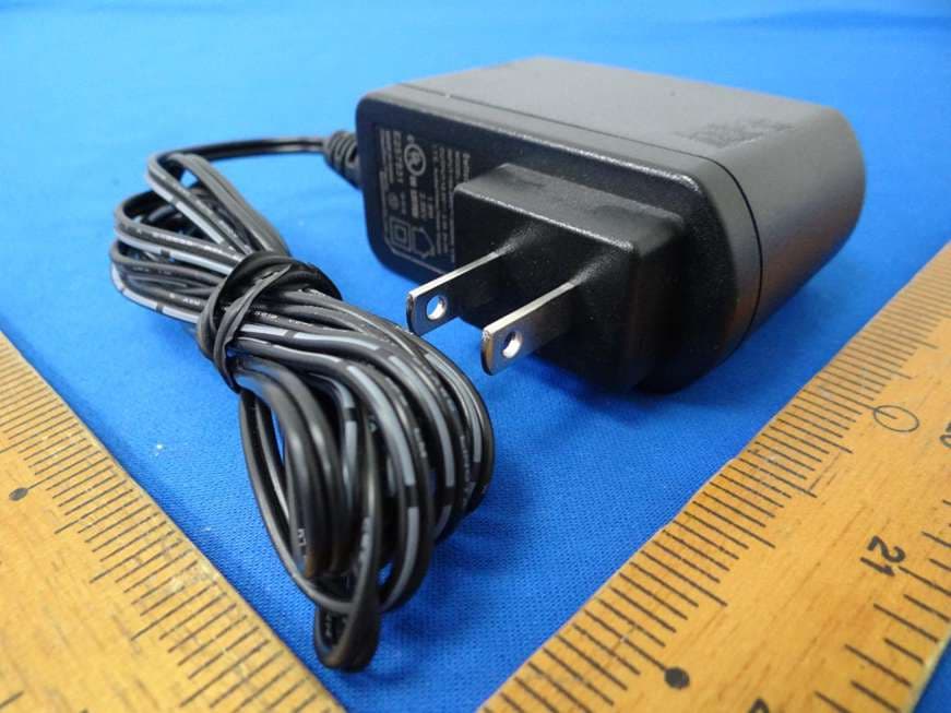
L9VWAP60AXD
Jun 07, 2022Home Gateway
Equipment Class
DTS - Digital Transmission System
L9VWAP5903
Apr 29, 2020AC1200 Dual Band WiFi Mesh Extender
Equipment Class
DTS - Digital Transmission System
L9VVR3071
Jan 21, 2020Home Gateway
Equipment Class
DTS - Digital Transmission System
L9VPG-9142S
Jan 28, 2015Powerline Ethernet Adapter with WiFi
Equipment Class
DTS - Digital Transmission System