L9V-COMTREND5836Wireless Extender
Comtrend Corporation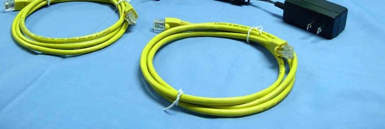
Click to zoom
Application Details
- Equipment Class
- NII - Unlicensed National Information Infrastructure TX
- Date of Grant
- Jul 10, 2012
- Application Purpose
- Original Equipment
- Date of Application
- Jul 09, 2012
- Equipment Note
- Wireless Extender
- Frequency Range
- 5180.00000000 - 5240.00000000
- Company
- Comtrend Corporation
- Country
- Taiwan
Documents & Files
Document Text
Text extracted from the exhibit documents filed with the FCC. Open a document above to read the original.
Users Manual
WAP-5836 Wireless Extender QUICK INSTALLATION GUIDE Introduction Easy Installa tion Step 1 - Power connection This Quick Installation Guide will help you to quick ly and easily install your Wireless Extender devices by performing the few simple steps described below. Before you begin, check that you have: • One WAP-5836 Wireless Extender • One CAT5 Ethernet Cable • One Power Adapter • One Quick Installation Guide Plug in the power adapter included in your package, and connect it to the WAP-5836 device. 1 Step 2 - Placement and connections A. Setting an AP device Using a power s upply with different voltage r ating than the o ne included with the WAP-5836 device may cause damage and void the warranty f or this p roduct. 1. Place one WAP-5836 device on an easily accessible surface near the Home Gateway or Router. Make sure the GW or Router is powered on and active. 2. Plug one end of the Ethernet cable into the LAN port of the Home Gateway device and the other end into the Ethernet port of the WAP-5836. 3. Ensure that the DHCP Server functionality on your Home Gateway or Router is enabled. The WAP-5836 device that gets a DHCP IP Address will be automatically set in Access Point (AP) mode for a simplified setup process. 2 B.Setting a Client device Make sure that the LED on the WAP-5836 is flashing blue. 1. Place another WAP-5836 device on an easily accessible surface near the set top box. Plug one end of the Ethernet cable into the LAN port of the Set Top Box and the other end into the Ethernet port of the WAP-5836. 2. Since the STB will not issue an IP address to the WAP-5836, it will automatically be set to Client mode. Make sure that the LED on the WAP-5836 Client is flashing blue. For best wireless performance, place the devices on a shelf or other elevated location and away from large metallic objects. 3 Pairing Step 1. Pair the devices: For initial pairing, it is recommended that you place the WAP-5836 AP and Client devices within the same room. Once paired, they can then be put in their desired locations. Press the WPS button on the “AP” front panel for 3-5 seconds and release it. The LED will begin flashing blue. Press the WPS button on the “Client” for 3-5 seconds and release it. The LED will begin flashing blue. WPS WPS NOTE – The WPS buttons can be pressed in any order as long as they are pressed within 2 minutes of each other. Step 2. Wait for the pairing process to complete by watching the LEDs on the devices: • The LEDs will flash blue for a few seconds after pressing the WPS button for both AP & Client. • The LEDs will change to solid blue after successful pairing and turn off two minutes later. • The Wireless LEDs will then be solid blue. • The Client wireless LED could be solid amber when the association is not able to receive a high quality HD stream. If pairing is unsuccessful: • The LEDs will flash blue for two minutes and then turn off. WPS WPS Wireless WPS Button 4 Congratulations! You have finished installing your new Wireless Extender devices. To test your connectivity, turn on the TV and set top box, and then watch any available TV channel. Note: To add additional WAP-5836 Clients to your network, you will need to perform the pairing procedures as explained above. Troubleshooting • The LED is not on • The LED is not on Make sure that: • The power cord is connected to the device, and that the power adapter is properly connected to a functioning power outlet. • You are using the power adapter that was supplied with the product. Make sure that: • The LAN cable connectors are securely plugged in at the WAP-5836 and at the network device (gateway, modem or set top box). • The connected network device is turned on. • You are using the correct cable type for your Ethernet equipment, which is at least UTP CAT5 with RJ45 connectors. Power Advanced Settings via the Web-based User Interface The instructions below are for users who have adequate networking knowledge. Users are not encouraged to configure the following settings because this may cause connectivity issues. 5 Step 1. Step 2. Note: • If you are connecting to the WAP-5836 directly from a PC, be sure to set a static IP in the same range as the AP or Client unit (e.g. 10.0.0.25) to access the Web Configuration page. • If the WAP-5836 is connected to a Gateway or Router that has a DHCP server, it will automatically get an IP address from that device. Be sure to check your Gateway or Router to see what IP address was given to the WAP-5836 units and use that to log in to the Web Configuration page. Log into the WAP-5836 web GUI through a browser such as IE with either the IP address the device was given by your DHCP server, or the default IP address of 10.0.0.10 for devices that have yet to be paired. Type default Username: root and Password: 12345 Advanced Troubleshooting • The WPS function is not working Make sure that: • The devices are in either AP or Client mode. • The WPS function is activated on the AP device. a. Enter into the WAP-5836 Web GUI b. Type default Username: root and Password: 12345 6 Wireless • Complete the pairing procedures as described in the Pairing section. • The LED is not on • Make sure that you have completed a successful pairing procedure as described in the Pairing section. FOR MORE HELP: If you have further questions or require personal assistance, please contact your equipment provider. c. Change the security mode to WPA2-PSK in Security Settings by selecting it in the drop-down menu. d. Enable WPS in WPS settings and press the “Apply” button. 7 WAP-5836_QIG_V1.1 This device complies with part 15 of the FCC Rules. Operation is subject to the following two conditions: (1) This device may not cause harmful interference, and (2) this device must accept any interference received, including interference that may cause undesired operation. The operation frequency of the device is in the 5150-5250 MHz band is for indoor use only. This equipment has been tested and found to comply with the limits f…
Text truncated - open the document above for the full version.
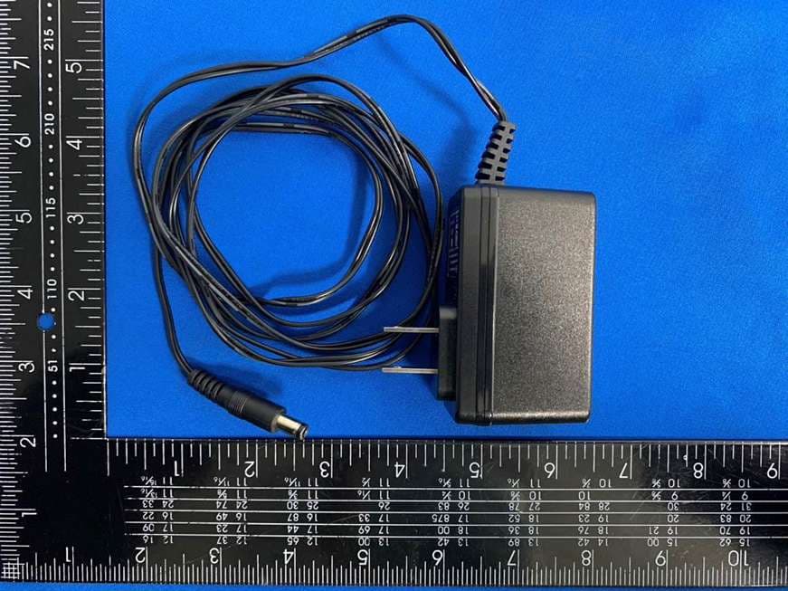
External Photos
Report No:122154R-RFUSP46V01 Page: 207 of 213 Attachement EUT Photograph (1) EUT Photo (2) EUT Photo
ID Label/Location Info
\\S-hc-fsr\emc_report\2012\2 \122154R \ \, label here.jpg 月 宏道 內部照片
Internal Photos
Report No:122154R-RFUSP46V01 Page: 208 of 213 (3) EUT Photo (4) EUT Photo Report No:122154R-RFUSP46V01 Page: 209 of 213 (5) EUT Photo (6) EUT Photo Report No:122154R-RFUSP46V01 Page: 210 of 213 (7) EUT Photo (8) EUT Photo Report No:122154R-RFUSP46V01 Page: 211 of 213 (9) EUT Photo (10) EUT Photo Report No:122154R-RFUSP46V01 Page: 212 of 213 (11) EUT Photo Report No:122154R-RFUSP46V01 Page: 213 of 213 (12) EUT Photo
RF Exposure Info
Report No. 122154R-RF-US-Exp Page: 1 of 5 RF Exposure Evaluation declaration Product Name :Wireless Extender Model No. :WAP-5836 FCC ID. :L9V-COMTREND5836 Applicant : Comtrend Corporation Address : 3F-1, 10 Lane 609, Chongxin Rd., Section 5, Sanchong Dist, New Taipei City 24159, Taiwan Date of Receipt : 2012/02/07 Date of Declaration : 2012/04/10 Report No. : 122154R-RF-US-Exp Report Version : V1.0 The declaration results relate only to the samples calculated. The declaration shall not be reproduced except in full without the written approval of QuieTek Corporation. Report No. 122154R-RF-US-Exp Page: 2 of 5 1. RF Exposure Evaluation 1.1. Limits According to FCC 1.1310: The criteria listed in the following table shall be used to evaluate the environment impact of human exposure to radio frequency (RF) radiation as specified in 1.1307(b) LIMITS FOR MAXIMUM PERMISSIBLE EXPOSURE (MPE) Frequency Range (MHz) Electric Field Strength (V/m) Magnetic Field Strength (A/m) Power Density (mW/cm 2 ) Average Time (Minutes) (A) Limits for Occupational/ Control Exposures 300-1500 -- -- F/300 6 1500-100,000 -- -- 5 6 (B) Limits for General Population/ Uncontrolled Exposures 300-1500 -- -- F/1500 6 1500-100,000 -- -- 1 30 F= Frequency in MHz Friis Formula Friis transmission formula: Pd = (Pout*G)/(4*pi*r 2 ) Where Pd = power density in mW/cm 2 Pout = output power to antenna in mW G = gain of antenna in linear scale Pi = 3.1416 R = distance between observation point and center of the radiator in cm Pd id the limit of MPE, 1 mW/cm 2 . If we know the maximum gain of the antenna and the total power input to the antenna, through the calculation, we will know the distance r where the MPE limit is reached. 1.2. Test Procedure Software provided by client enabled the EUT to transmit and receive data at lowest, middle and highest channel individually. The temperature and related humidity: 18°Cand 78% RH. Report No. 122154R-RF-US-Exp Page: 3 of 5 1.3. Test Result of RF Exposure Evaluation Product Wireless Extender Test Mode Transmit Test Condition RF Exposure Evaluation Antenna Gain Antenna Gain: The maximum Gain measured in fully anechoic chamber is 2dBi or 1.58 in linear scale. Output Power into Antenna & RF Exposure Evaluation Distance: IEEE 802.11a WLAN Function Channel Channel Frequency (MHz) Output Power to Antenna (mW) Power Density at R = 20 cm (mW/cm 2 ) 36 5180 48.19 0.0151 44 5220 49.09 0.0154 48 5240 47.86 0.0150 IEEE 802.11a WLAN Function Channel Channel Frequency (MHz) Output Power to Antenna (mW) Power Density at R = 20 cm (mW/cm 2 ) 149 5745 281.8383 0.08859 157 5785 248.3133 0.07805 165 5825 196.3360 0.06171 The power density Pd (4th column) at a distance of 20 cm calculated from the Friis transmission formula is far below the limit of 1 mW/cm 2 . Report No. 122154R-RF-US-Exp Page: 4 of 5 Product Wireless Extender Test Mode Transmit Test Condition RF Exposure Evaluation Antenna Gain Antenna Gain: The maximum Gain measured in fully anechoic chamber is 2dBi or 1.58 in linear scale. Output Power into Antenna & RF Exposure Evaluation Distance: IEEE 802.11 n(20MHz) WLAN Function Channel Channel Frequency (MHz) Output Power to Antenna (mW) Power Density at R = 20 cm (mW/cm 2 ) 36 5180 49.89 0.0157 44 5220 29.92 0.0094 48 5240 26.73 0.0084 IEEE 802.11 n(20MHz) WLAN Function Channel Channel Frequency (MHz) Output Power to Antenna (mW) Power Density at R = 20 cm (mW/cm 2 ) 149 5745 534.5644 0.16803 157 5785 426.5795 0.13409 165 5825 302.6913 0.09515 The power density Pd (4th column) at a distance of 20 cm calculated from the Friis transmission formula is far below the limit of 1 mW/cm 2 . Report No. 122154R-RF-US-Exp Page: 5 of 5 Product Wireless Extender Test Mode Transmit Test Condition RF Exposure Evaluation Antenna Gain Antenna Gain: The maximum Gain measured in fully anechoic chamber is 2dBi or 1.58 in linear scale. Output Power into Antenna & RF Exposure Evaluation Distance: IEEE 802.11 n(40MHz) WLAN Function Channel Channel Frequency (MHz) Output Power to Antenna (mW) Power Density at R = 20 cm (mW/cm 2 ) 38 5190 42.66 0.0134 46 5230 43.85 0.0138 IEEE 802.11 n(40MHz) WLAN Function Channel Channel Frequency (MHz) Output Power to Antenna (mW) Power Density at R = 20 cm (mW/cm 2 ) 151 5755 464.5153 0.14601 159 5795 332.6596 0.10456 The power density Pd (4th column) at a distance of 20 cm calculated from the Friis transmission formula is far below the limit of 1 mW/cm 2 .
Test Report
Report No:122154R-RFUSP46V01 Page: 1 of 213 Test Report Product Name:Wireless Extender Model No. :WAP-5836 FCC ID. :L9V-COMTREND5836 Applicant : Comtrend Corporation Address : 3F-1, 10 Lane 609, Chongxin Rd., Section 5, Sanchong Dist, New Taipei City 24159, Taiwan Date of Receipt:2012/02/07 Issued Date :2012/07/09 Report No. :122154R-RFUSP46V01 Report Version :V1.0 The test results relate only to the samples tested. The test report shall not be reproduced except in full without the written approval of QuieTek Corporation. Report No:122154R-RFUSP46V01 Page: 2 of 213 Test Report Certification Issued Date : 2012/07/09 Report No. : 122154R-RFUSP46V01 Product Name : Wireless Extender Applicant : Comtrend Corporation Address : 3F-1, 10 Lane 609, Chongxin Rd., Section 5, Sanchong Dist, New Taipei City 24159, Taiwan Manufacturer : Ayecom Technology Co., Ltd. Model No. : WAP-5836 FCC ID. : L9V-COMTREND5836 EUT Voltage : AC 100-120V 50-60Hz Trade Name : Comtrend Applicable Standard : FCC CFR Title 47 Part 15 Subpart E Section 15.407: 2010 ANSI C63.4: 2009 Test Result : Complied The test results relate only to the samples tested. The test report shall not be reproduced except in full without the written approval of QuieTek Corporation. Documented By : ( Sandy Chuang / Adm. Specialist ) Reviewed By : ( JuBo Shen / Engineer ) Approved By : ( Roy Wang / Manager ) Report No:122154R-RFUSP46V01 Page: 3 of 213 TABLE OF CONTENTS Description Page 1. General Information...................................................................................................................... 5 1.1. EUT D ESCRIPTION........................................................................................................................ 5 1.2. O PERATIONAL DESCRIPTION........................................................................................................ 10 1.3. T EST MODE................................................................................................................................11 1.4. T ESTED SYSTEM DETAILS............................................................................................................ 12 1.5. C ONFIGURATION OF TESTED SYSTEM........................................................................................... 12 1.6. EUT E XERCISE SOFTWARE......................................................................................................... 13 1.7. T EST FACILITY............................................................................................................................ 14 2. Conducted Emission .................................................................................................................. 16 2.1. T EST EQUIPMENT........................................................................................................................ 16 2.2. T EST SETUP...............................................................................................................................16 2.3. L IMITS........................................................................................................................................ 17 2.4. T EST PROCEDURE...................................................................................................................... 17 2.5. T EST SPECIFICATION................................................................................................................... 17 2.6. U NCERTAINTY............................................................................................................................. 17 2.7. T EST RESULT.............................................................................................................................. 18 2.8. T EST PHOTO...............................................................................................................................20 3. 99% & 26dB Bandwidth .............................................................................................................. 21 3.1. T EST EQUIPMENT........................................................................................................................ 21 3.2. T EST SETUP...............................................................................................................................21 3.3. L IMITS........................................................................................................................................ 21 3.4. T EST PROCEDURE...................................................................................................................... 21 3.5. U NCERTAINTY............................................................................................................................. 21 3.6. T EST RESULT.............................................................................................................................. 22 4. Peak Transmit Output................................................................................................................. 40 4.1. T EST EQUIPMENT........................................................................................................................ 40 4.2. T EST SETUP...............................................................................................................................40 4.3. L IMITS........................................................................................................................................ 41 4.4. T EST PROCEDURE...................................................................................................................... 41 4.5. U NCERTAINTY............................................................................................................................. 41 4.6. T EST RESULT.............................................................................................................................. 42 5. Peak Power Spectrum Density .........................................................…
Text truncated - open the document above for the full version.
Test Report
Report No:122154R-RFUSP46V01 Page: 70 of 213 5. Peak Power Spectrum Density 5.1. Test Equipment The following test equipments are used during the radiated emission tests: Peak Power Spectrum Density / SR7 Instrument Manufacturer Model No. Serial No Next Cal. Date Spectrum Analyzer R&S FSP 100561 2013/02/19 Note: 1. All equipments that need to calibrate are with calibration period of 1 year. 5.2. Test Setup 5.3. Limits 1. For the band 5.15-5.25 GHz, the peak power spectral density shall not exceed 4 dBm in any 1-MHz band. If transmitting antenna of directional gain greater than 6 dBi are used, the peak power spectral density shall be reduced by the amount in dB that directional gain of the antenna exceeds 6 dBi. 2. For the band 5.25-5.35 GHz, the peak power spectral density shall not exceed 11 dBm in any 1-MHz band. If transmitting antenna of directional gain greater than 6 dBi are used, the peak power spectral density shall be reduced by the amount in dB that directional gain of the antenna exceeds 6 dBi. 3. For the band 5.725-5.825 GHz, the peak power spectral density shall not exceed 17 dBm in any 1-MHz band. If transmitting antenna of directional gain greater than 6 dBi are used, the peak power spectral density shall be reduced by the amount in dB that directional gain of the antenna exceeds 6 dBi. Report No:122154R-RFUSP46V01 Page: 71 of 213 5.4. Test Procedure The EUT was setup to ANSI C63.4, 2009; tested to U-NII test procedure of March 2012 KDB 789033 for compliance to FCC 47CFR Subpart E requirements. Set RBW=1MHz, VBW=3MHz with RMS detector. The PPSD is the highest level found across the emission in any 1-MHz band after 100 sweeps of averaging. 5.5. Uncertainty The measurement uncertainty is defined as ± 1.27 dB Report No:122154R-RFUSP46V01 Page: 72 of 213 5.6. Test Result Product Wireless Extender Test Item Peak Power Spectral Density Test Mode Mode 1: Transmit Date of Test 2012/04/05 Test Site SR7 IEEE 802.11a Channel No. Frequency (MHz) Measure Level (dBm) Required Limit (dBm) Result 36 5180 3.044 ≦4 Pass 44 5220 3.673 ≦4 Pass 48 5240 3.945 ≦4 Pass Report No:122154R-RFUSP46V01 Page: 73 of 213 Peak Power Spectral Density – Channel 36 Peak Power Spectral Density – Channel 44 Report No:122154R-RFUSP46V01 Page: 74 of 213 Peak Power Spectral Density – Channel 48 Report No:122154R-RFUSP46V01 Page: 75 of 213 Product Wireless Extender Test Item Peak Power Spectral Density Test Mode Mode 1: Transmit Date of Test 2012/04/05 Test Site SR7 IEEE 802.11n (20MHz), (ANT 0) Channel No. Frequency (MHz) Measure Level (dBm) Required Limit (dBm) Result 36 5180 -0.397 ≦4 Pass 44 5220 -1.004 ≦4 Pass 48 5240 -1.391 ≦4 Pass Report No:122154R-RFUSP46V01 Page: 76 of 213 Peak Power Spectral Density – Channel 36 Peak Power Spectral Density – Channel 44 Report No:122154R-RFUSP46V01 Page: 77 of 213 Peak Power Spectral Density – Channel 48 Report No:122154R-RFUSP46V01 Page: 78 of 213 Product Wireless Extender Test Item Peak Power Spectral Density Test Mode Mode 1: Transmit Date of Test 2012/04/05 Test Site SR7 IEEE 802.11n (20MHz), (ANT 1) Channel No. Frequency (MHz) Measure Level (dBm) Required Limit (dBm) Result 36 5180 -1.199 ≦4 Pass 44 5220 -1.719 ≦4 Pass 48 5240 -1.938 ≦4 Pass Report No:122154R-RFUSP46V01 Page: 79 of 213 Peak Power Spectral Density – Channel 36 Peak Power Spectral Density – Channel 44 Report No:122154R-RFUSP46V01 Page: 80 of 213 Peak Power Spectral Density – Channel 48 Report No:122154R-RFUSP46V01 Page: 81 of 213 Product Wireless Extender Test Item Peak Power Spectral Density Test Mode Mode 1: Transmit Date of Test 2012/04/05 Test Site SR7 IEEE 802.11n (20MHz), (ANT 2) Channel No. Frequency (MHz) Measure Level (dBm) Required Limit (dBm) Result 36 5180 -1.204 ≦4 Pass 44 5220 -0.855 ≦4 Pass 48 5240 -1.170 ≦4 Pass Report No:122154R-RFUSP46V01 Page: 82 of 213 Peak Power Spectral Density – Channel 36 Peak Power Spectral Density – Channel 46 Report No:122154R-RFUSP46V01 Page: 83 of 213 Peak Power Spectral Density – Channel 48 Report No:122154R-RFUSP46V01 Page: 84 of 213 Product Wireless Extender Test Item Peak Power Spectral Density Test Mode Mode 1: Transmit Date of Test 2012/04/05 Test Site SR7 IEEE 802.11n (20MHz) (ANT 0+1+2) Channel No. Frequency (MHz) Measure Level (dBm) Required Limit (dBm) Result 36 5180 3.850 ≦4 Pass 44 5220 3.590 ≦4 Pass 48 5240 3.280 ≦4 Pass Report No:122154R-RFUSP46V01 Page: 85 of 213 Product Wireless Extender Test Item Peak Power Spectral Density Test Mode Mode 1: Transmit Date of Test 2012/04/05 Test Site SR7 IEEE 802.11n (40MHz), (ANT 0) Channel No. Frequency (MHz) Measure Level (dBm) Required Limit (dBm) Result 38 5190 -2.324 ≦4 Pass 46 5230 -1.870 ≦4 Pass Report No:122154R-RFUSP46V01 Page: 86 of 213 Peak Power Spectral Density – Channel 38 Peak Power Spectral Density – Channel 46 Report No:122154R-RFUSP46V01 Page: 87 of 213 Product Wireless Extender Test Item Peak Power Spectral Density Test Mode Mode 1: Transmit Date of Test 2012/04/05 Test Site SR7 IEEE 802.11n (40MHz), (ANT 1) Channel No. Frequency (MHz) Measure Level (dBm) Required Limit (dBm) Result 38 5190 -3.277 ≦4 Pass 46 5230 -2.604 ≦4 Pass Report No:122154R-RFUSP46V01 Page: 88 of 213 Peak Power Spectral Density – Channel 38 Peak Power Spectral Density – Channel 46 Report No:122154R-RFUSP46V01 Page: 89 of 213 Product Wireless Extender Test Item Peak Power Spectral Density Test Mode Mode 1: Transmit Date of Test 2012/04/05 Test Site SR7 IEEE 802.11n (40MHz), (ANT 2) Channel No. Frequency (MHz) Measure Level (dBm) Required Limit (dBm) Result 38 5190 -1.543 ≦4 Pass 46 5230 -1.537 ≦4 Pass Report No:122154R-RFUSP46V01 Page: 90 of 213 Peak Power Spectral Density – Channel 38 Peak Power Spectral Density – Channel 46 Report No:122154R-RFUSP46V01 Page: 91 of 213 Product Wireless Extender Test Item Peak Power Spectral Density Test Mode Mode 1: Transmit Date of Test 2012/04/05 Test Site SR7 IEEE 802.11n (40MHz) (ANT 0+1+2) Channel No. Frequency (MHz) Measure Level (dBm) Required Limit (dBm) Result 38 5190 2.450…
Text truncated - open the document above for the full version.
Test Setup Photos
Report No:122154R-RFUSP46V01 Page: 20 of 213 2.8. Test Photo Test Mode : Mode 1: Transmit Description: Front View of Conducted Emission Test Setup Test Mode : Mode 1: Transmit Description: Back View of Conducted Emission Test Setup Report No:122154R-RFUSP46V01 Page: 152 of 213 7.7. Test Photo Test Mode : Mode 1: Transmit Description: Front View of Radiated Emission Test Setup (Bi-Log) Test Mode : Mode 1: Transmit Description: Back View of Radiated Emission Test Setup (Bi-Log) Report No:122154R-RFUSP46V01 Page: 153 of 213 Test Mode : Mode 1: Transmit Description: Front View of Radiated Emission Test Setup (Horn) Test Mode : Mode 1: Transmit Description: Back View of Radiated Emission Test Setup (Horn)
Contact Information
Applicant
Bill Wang
Technical Contact
QuieTek CorporationNeil Yeh
[email protected]886-3-5928858
N0. 75-2, 3rd Lin, Wangye Keng · Hsinchu County · Taiwan
Test Firm
QuieTek CorporationWarren Lin
Technical Specifications
| # | Rule Parts | Frequency Range | Power Output |
|---|---|---|---|
| 1 | 15E | 5.18 GHz - 5.24 GHz | 49.90 mW |
Other Applications from Comtrend Corporation
L9VVR3071V2
Nov 30, 2023Home Gateway
Equipment Class
DTS - Digital Transmission System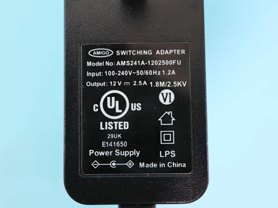
L9VPRT6351
Jul 04, 2023Home Gateway
Equipment Class
DTS - Digital Transmission System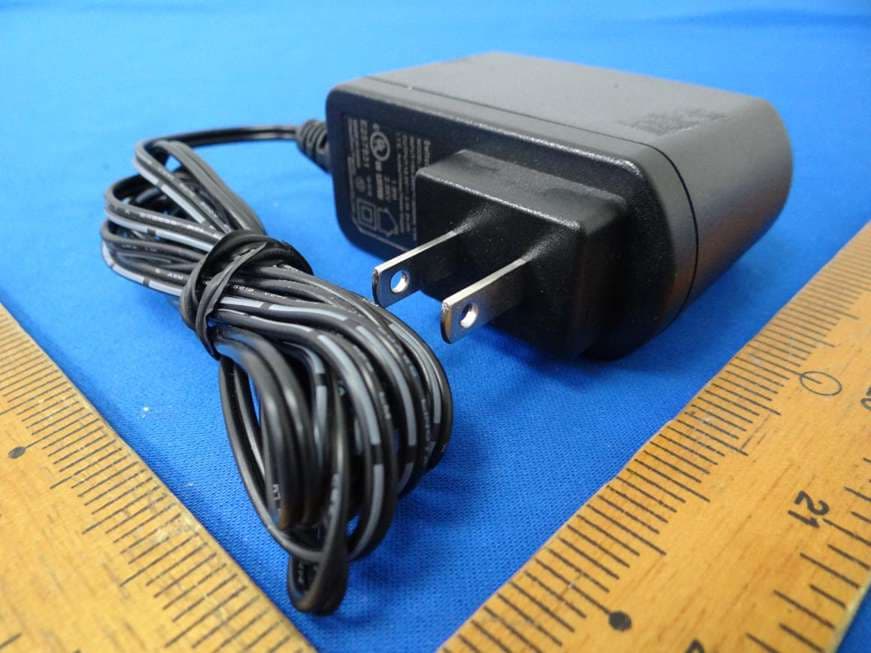
L9VWAP60AXD
Jun 07, 2022Home Gateway
Equipment Class
DTS - Digital Transmission System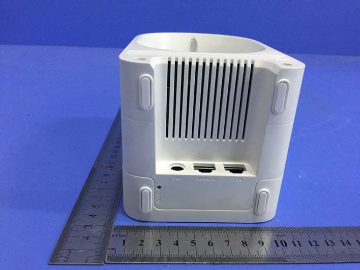
L9VWAP5903
Apr 29, 2020AC1200 Dual Band WiFi Mesh Extender
Equipment Class
DTS - Digital Transmission System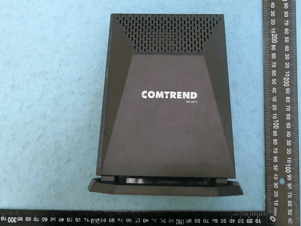
L9VVR3071
Jan 21, 2020Home Gateway
Equipment Class
DTS - Digital Transmission System