L9V-CT-5364A11N Wireless ADSL2+Router
Comtrend Corporation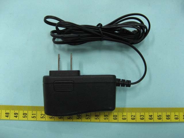
Click to zoom
Application Details
- Equipment Class
- DTS - Digital Transmission System
- Date of Grant
- May 29, 2010
- Application Purpose
- Original Equipment
- Date of Application
- May 29, 2010
- Equipment Note
- 11N Wireless ADSL2+Router
- Frequency Range
- 2422.00000000 - 2452.00000000
- Company
- Comtrend Corporation
- Country
- Taiwan
Documents & Files
Document Text
Text extracted from the exhibit documents filed with the FCC. Open a document above to read the original.
Users Manual
CT-5364A 802.11n ADSL2+ Router User Manual Version A2.0, May 17, 2010 261091-007 1 Preface This manual provides information related to the installation and operation of this device. The individual reading this manual is presumed to have a basic understanding of telecommunications terminology and concepts. If you find the product to be inoperable or malfunctioning, please contact technical support for immediate service by email at [email protected] For product update, new product release, manual revision, or software upgrades, please visit our website at http://www.comtrend.com Important Safety Instructions With reference to unpacking, installation, use, and maintenance of your electronic device, the following basic guidelines are recommended: • Do not use or install this product near water, to avoid fire or shock hazard. For example, near a bathtub, kitchen sink or laundry tub, or near a swimming pool. Also, do not expose the equipment to rain or damp areas (e.g. a wet basement). • Do not connect the power supply cord on elevated surfaces. Allow it to lie freely. There should be no obstructions in its path and no heavy items should be placed on the cord. In addition, do not walk on, step on, or mistreat the cord. • Use only the power cord and adapter that are shipped with this device. • To safeguard the equipment against overheating, make sure that all openings in the unit that offer exposure to air are not blocked. • Avoid using a telephone (other than a cordless type) during an electrical storm. There may be a remote risk of electric shock from lightening. Also, do not use the telephone to report a gas leak in the vicinity of the leak. • Never install telephone wiring during stormy weather conditions. CAUTION: To reduce the risk of fire, use only No. 26 AWG or larger telecommunication line cord. Always disconnect all telephone lines from the wall outlet before servicing or disassembling this equipment. WARNING Disconnect the power line from the device before servicing. Power supply specifications are clearly stated in Appendix C. 2 FCC Compliance This device complies with Part 15 of the FCC Rules. Operation is subject to the following two conditions:(1) this device may not cause harmful interference, and (2) this device must accept any interference received, including interference that may cause undesired operation. Notice: The changes or modifications not expressly approved by the party responsible for compliance could void the user’s authority to operate the equipment. IMPORTANT NOTE: To comply with the FCC RF exposure compliance requirements, no change to the antenna or the device is permitted. Any change to the antenna or the device could result in the device exceeding the RF exposure requirements and void user’s authority to operate the device. The Federal Communication Commission Radio Frequency Interference Statement includes the following paragraph: The equipment has been tested and found to comply with the limits for a Class Digital Device, pursuant to part 15 of the FCC Rules. These limits are designed to provide reasonable protection against harmful interference in a residential installation. This equipment generates, uses and can radiate radio frequency energy and, if not installed and used in accordance with the instruction, may cause harmful interference to radio communication. However, there is no grantee that interference will not occur in a particular installation. If this equipment dose cause harmful interference to radio or television reception, which can be determined by turning the equipment off and on, the user is encouraged to try to correct the interference by one or more of the following measures: --Reorient or relocate the receiving antenna. --Increase the separation between the equipment and receiver. --Connect the equipment into an outlet on a circuit different from that to which the receiver is connected. --Consult the dealer or an experienced radio/TV technician for help. The user should not modify or change this equipment without written approval form Comtrend Corporation .Modification could void authority to use this equipment. IMPORTANT NOTE: To comply with the FCC RF exposure compliance requirements, the antenna(s) used for this transmitter must be installed to provide a separation distance of at least 20 cm from all persons and must not be co-located or operating in conjunction with any other antenna or transmitter. No change to the antenna or the device is permitted. Any change to the antenna or the device could result in the device exceeding the RF exposure requirements and void user’s authority to operate the device. 3 Copyright Copyright©2010 Comtrend Corporation. All rights reserved. The information contained herein is proprietary to Comtrend Corporation. No part of this document may be translated, transcribed, reproduced, in any form, or by any means without prior written consent of Comtrend Corporation. This program is free software: you can redistribute it and/or modify it under the terms of the GNU General Public License as published by the Free Software Foundation, either version 3 of the License, or (at your option) any later version. This program is distributed in the hope that it will be useful, but WITHOUT ANY WARRANTY; without even the implied warranty of MERCHANTA ILITY or FITNESS FOR A PARTICULAR PURPOSE. See the GNU General Public License for more details. You should have received a copy of the GNU General Public License along with this program. If not, see http://www.gnu.org/licenses/ NOTE: This document is subject to change without notice. Protect Our Environment This symbol indicates that when the equipment has reached the end of its useful life, it must be taken to a recycling centre and processed separate from domestic waste. The cardboard box, the plastic contained in the packaging, and the parts that make up this router can be recycled in accordance with regionally established regulations. Never dispose of thi…
Text truncated - open the document above for the full version.
External Photos
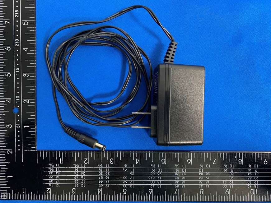
ETC Report No. : 10-03-RBF-009-01 FCC ID.: L9V-CT-5364A Rev. No 1.0 CONSTRUCTION PHOTOS OF EUT Top View of EUT Bottom View of EUT ETC Report No. : 10-03-RBF-009-01 FCC ID.: L9V-CT-5364A Rev. No 1.0 CONSTRUCTION PHOTOS OF EUT Front View of EUT Side View of EUT ETC Report No. : 10-03-RBF-009-01 FCC ID.: L9V-CT-5364A Rev. No 1.0 CONSTRUCTION PHOTOS OF EUT Rear View of EUT Side View of EUT ETC Report No. : 10-03-RBF-009-01 FCC ID.: L9V-CT-5364A Rev. No 1.0 CONSTRUCTION PHOTOS OF EUT Mode: Adaptor Top View of Adaptor Bottom View of Adaptor
ID Label/Location Info
910805 1 LABEL 80mm 30mm
Internal Photos
ETC Report No. : 10-03-RBF-009-01 FCC ID.: L9V-CT-5364A Rev. No 1.0 CONSTRUCTION PHOTOS OF EUT Internal View of EUT Internal View of EUT ETC Report No. : 10-03-RBF-009-01 FCC ID.: L9V-CT-5364A Rev. No 1.0 CONSTRUCTION PHOTOS OF EUT Component View of PCB Component View of PCB ETC Report No. : 10-03-RBF-009-01 FCC ID.: L9V-CT-5364A Rev. No 1.0 CONSTRUCTION PHOTOS OF EUT Solder View of PCB ETC Report No. : 10-03-RBF-009-01 FCC ID.: L9V-CT-5364A Rev. No 1.0 CONSTRUCTION PHOTOS OF EUT Component View of Adaptor’s PCB Component View of Adaptor’s PCB
RF Exposure Info
FCC ID: L9V-CT-5364A RF Exposure Evaluation of E.U.T. : 11N Wireless ADSL2+Router FCC ID. : L9V-CT-5364A MODEL : CT-5364A SERIAL MODEL : CT-5364A NA for APPLICANT : Comtrend Corporation ADDRESS : 3F-1, 10 Lane 609, Chung Hsin Road, Section 5 San Chung City, Tapei Hsien, Taiwan, 241 Prepared by ELECTRONICS TESTING CENTER, TAIWAN NO. 34. LIN 5. DINGFU TSUEN, LINKOU SHIANG TAIPEI COUNTY, TAIWAN, 24442, R.O.C. Tel:(02)26023052 Fax:(02)26010910 http://www.etc.org.tw ; e-mail: [email protected] Report Number : 10-04-RBF-028-MPE FCC ID: L9V-CT-5364A Product Information: Type of EUT: 11N Wireless ADSL2+Router FCC ID: L9V-CT-5364A Manufacturer: Comtrend Corporation Model: CT-5364A Serial Model: CT-5364A NA Description: Frequency Range: 2.400GHz-2.4835GHz Modulation Technique: Orthogonal frequency division multiplexing (OFDM) Direct Seqiemce Spread Spectrum (CCK, DQPSK, DBPSK) Maximum conducted output power (measured): 25.762 dBm or 376.95mW The following table lists the provided authorized antennas: Antenna Gain Model Antenna Type (dBi) Numeric GY111HT503-005 Dipole-type Antenna 2.72 1.87 Below is an example of the RF Exposure Statement: IMPORTANT NOTE: To comply with the FCC RF exposure compliance requirements, the antenna(s) used for this transmitter must be installed to provide a separation distance of at least 20 cm from all persons and must not be co-located or operating in conjunction with any other antenna or transmitter. No change to the antenna or the device is permitted. Any change to the antenna or the device could result in the device exceeding the RF exposure requirements and void user’s authority to operate the device. FCC ID: L9V-CT-5364A Relative Requirement for Compliance According to section 1.1310 of FCC 47 CFR Part 1, limits for maximum permissible exposure (MPE) are as following: TABLE 1 – LIMITS FOR MAXIMUN PERMISSIBLE EXPOSURE (MPE) Frequency Range (MHz) Electric Field Strength (V/m) Magnetic Field Strength (A/m) Power Density (mW/cm 2 ) Averaging Time (minutes) (A) Limits for Occupational/Controlled Exposures 0.3-3.0 .................. 614 1.63 *(100) 6 3-30 ..................... 1842/f 4.89/f *(900/f 2 ) 6 30-300 .................. 61.4 0.163 1.0 6 300-1500 ............... ...................... ...................... f/300 6 1500-100,000 ......... ...................... ...................... 5 6 (B) Limits for General Population/Uncontrolled Exposure 0.3-1.34 ............... 614 1.63 *(100) 30 1.34-30 ............... 824/f 2.19/f *(180/f2) 30 30-300 .................. 27.5 0.073 0.2 30 300-1500 ............... ...................... ...................... f/1500 30 1500-100,000 ......... ...................... ...................... 1.0 30 f = frequency in MHz * = Plane-wave equivalent power density NOTE 1 TO TABLE 1: Occupational/controlled limits apply in situations in which persons are exposed as a consequence of their employment provided those persons are fully aware of the potential for exposure and can exercise control over their exposure. Limits for occupational/controlled exposure also apply in situations when an individual is transient through a location where occupational / controlled limits apply provided he or she is made aware of the potential for exposure. NOTE 2 TO TABLE 1: General population/uncontrolled exposures apply in situations in which the general public may be exposed, or in which persons that are exposed as a consequence of their employment may not be fully aware of the potential for exposure or can not exercise control over their exposure. FCC ID: L9V-CT-5364A RF Exposure Calculations: The following information provides the minimum separation distance for the highest gain antenna provided. This calculation is based on the highest EIRP possible from the system, considering maximum power and antenna gain, and considering a 1.0 mW/cm 2 uncontrolled exposure limit. The formula shown in OET Bulletin 65 is used in the calculation. Equation from page 19 of OET Bulletin 65, Edition 97-01 is: S= PG / 4R 2 where: S = power density (in appropriate units, e.g. mW/cm 2 ) P = power input to the antenna (in appropriate units, e.g., mW) G = power gain of the antenna in the direction of interest relative to an isotropic radiator R = distance to the center of radiation of the antenna (appropriate units, e.g., cm) hence R= PG / 4S) 1/2 For our device P = 376.95mW G = 1.87 R = 20 cm S = (376.95 * 1.87) / (4**20 2 ) = 0.31 mW/cm 2 < 1.0 mW/cm 2 For complying the FCC limits for general population/uncontrolled exposure, the power density limit is 1.0 mW/cm 2 . The calculation result of the power density at a distance of 20 cm of our device is less than the limit. This means that according to OET Bulletin 65 (Edition 97-01), Supplement C (Edition 01-01), the equipment fulfills the requirements on power density for general population/uncontrolled exposure and therefore fulfills the requirements of 47 CFR Part 15.247 (b)(5).
Test Report
Rev. No 2.0 FCC Part 15 EMI TEST REPORT of E.U.T. : 11N Wireless ADSL2+Router FCC ID. : L9V-CT-5364A Model No. : CT-5364A Serial Model : CT-5364A NA for APPLICANT : Comtrend Corporation ADDRESS : 3F-1, 10 Lane 609, Chung Hsin Road, Section 5 San Chung City, Tapei Hsien, Taiwan, 241 Test Performed by ELECTRONICS TESTING CENTER, TAIWAN NO.34, LIN 5, DINGFU TSUEN, LINKOU SHIANG TAIPEI COUNTY, TAIWAN, 24442, R.O.C. Tel : (02)26023052 Fax : (02)26010910 http://www.etc.org.tw ; e-mail: [email protected] Report Number : 10-03-RBF-009-01 ETC Report No. : 10-03-RBF-009-01 FCC ID.: L9V-CT-5364A Rev. No 1.0 TEST REPORT CERTIFICATION Applicant : Comtrend Corporation 3F-1, 10 Lane 609, Chung Hsin Road, Section 5 San Chung City, Tapei Hsien, Taiwan, 241 Manufacturer : Comtrend Corporation 3F-1, 10 Lane 609, Chung Hsin Road, Section 5 San Chung City, Tapei Hsien, Taiwan, 241 Description of EUT a) Type of EUT : 11N Wireless ADSL2+Router b) Trade Name : Comtrend c) Model No. : CT-5364A d) Serial Model : CT-5364A NA e) Power Supply : Adaptor Model No.: AMS9-1201000FU2-VP I/P: 100-240Vac 50/60Hz 0.5A; O/P: 12V---1.0A Regulation Applied : FCC Rules and Regulations Part 15 Subpart C (2008) I HEREBY CERTIFY THAT: The data shown in this report were made in accordance with the procedures given in ANSI C63.4, and the energy emitted by the device was founded to be within the limits applicable. I assume full responsibility for accuracy and completeness of these data. Note: 1. The result of the testing report relate only to the item tested. 2. The testing report shall not be reproduced expect in full, without the written approval of ETC. ETC Report No. : 10-03-RBF-009-01 FCC ID.: L9V-CT-5364A Rev. No 1.0 Date Test Item Received : Mar. 02, 2010 Date Test Campaign Completed : Mar. 22, 2010 Date of Issue : Apr. 19, 2010 Test Engineer : ( Falcon Shi, Engineer ) Check By : ( Charles Wang, Supervisor ) Approve & Authorized Signer : Will Yauo, Manager EMC Dept. II of ELECTRONICS TESTING CENTER, TAIWAN ETC Report No. : 10-03-RBF-009-01 FCC ID.: L9V-CT-5364A Rev. No 1.0 Table of Contents Page 1 GENERAL INFORMATION.......................................................................................................1 1.1 Product Description........................................................................................................................1 1.2 Characteristics of Device................................................................................................................1 1.3 Test Methodology..........................................................................................................................1 1.4 Test Facility....................................................................................................................................1 2 PROVISIONS APPLICABLE.......................................................................................................2 2.1 Definition........................................................................................................................................2 2.2 Requirement for Compliance...........................................................................................................3 2.3 Restricted Bands of Operation........................................................................................................5 2.4 Labeling Requirement.....................................................................................................................5 2.5 User Information............................................................................................................................6 3. SYSTEM TEST CONFIGURATION...........................................................................................7 3.1 Justification.....................................................................................................................................7 3.2 Devices for Tested System.............................................................................................................7 4 RADIATED EMISSION MEASUREMENT..............................................................................8 4.1 Applicable Standard.......................................................................................................................8 4.2 Measurement Procedure.................................................................................................................8 4.3 Measuring Instrument...................................................................................................................10 4.4 Radiated Emission Data................................................................................................................11 4.5 Field Strength Calculation.............................................................................................................28 4.6 Photos of Radiation Measuring Setup............................................................................................29 5 CONDUCTED EMISSION MEASUREMENT........................................................................30 5.1 Standard Applicable.....................................................................................................................30 5.2 Measurement Procedure...............................................................................................................30 5.3 Conducted Emission Data.............................................................................................................31 5.4 Result Data Calculation.................................................................................................................33 5.5 Conducted Measurement Equipment.............................................................................................33 5.6 Photos of Conduction Measuring Setup........................................................................................34 6 ANTENNA REQUIREMENT.................................…
Text truncated - open the document above for the full version.
Test Setup Photos
ETC Report No. : 10-03-RBF-009-01 FCC ID.: L9V-CT-5364A Rev. No 2.0 Photos of Radiation Measuring Setup ETC Report No. : 10-03-RBF-009-01 FCC ID.: L9V-CT-5364A Rev. No 2.0 Photos of Conduction Measuring Setup
Contact Information
Applicant
Bill Wang
Test Firm
Taiwan Testing and Certification CenterAnderson Ku
Technical Specifications
| # | Rule Parts | Frequency Range | Power Output |
|---|---|---|---|
| 3 | 15C | 2.42 GHz - 2.45 GHz | 270.00 mW |
Other Applications from Comtrend Corporation
L9VVR3071V2
Nov 30, 2023Home Gateway
Equipment Class
DTS - Digital Transmission System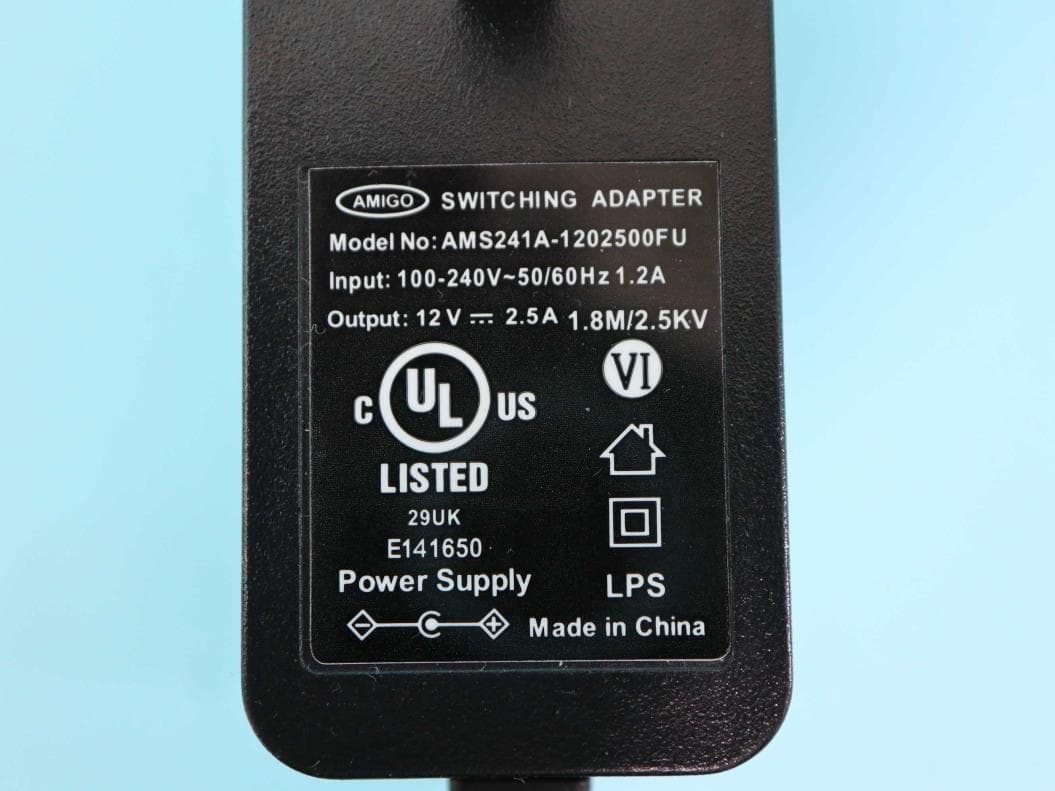
L9VPRT6351
Jul 04, 2023Home Gateway
Equipment Class
DTS - Digital Transmission System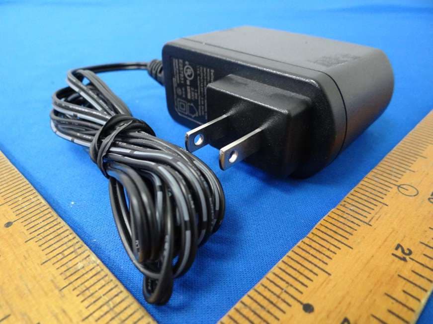
L9VWAP60AXD
Jun 07, 2022Home Gateway
Equipment Class
DTS - Digital Transmission System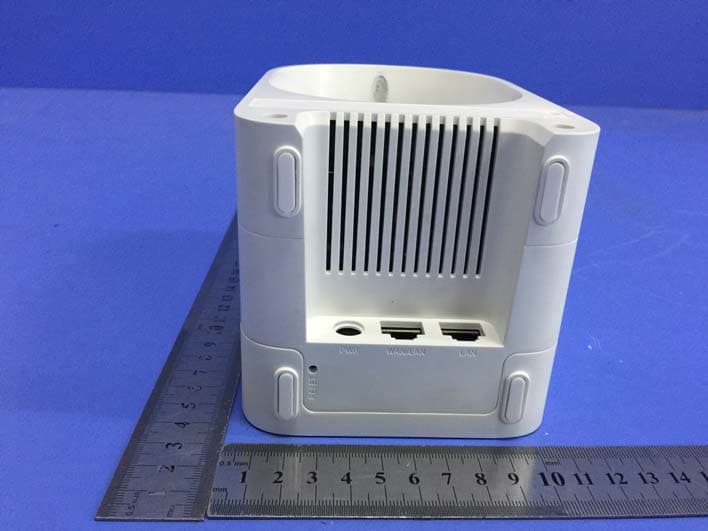
L9VWAP5903
Apr 29, 2020AC1200 Dual Band WiFi Mesh Extender
Equipment Class
DTS - Digital Transmission System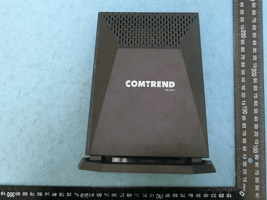
L9VVR3071
Jan 21, 2020Home Gateway
Equipment Class
DTS - Digital Transmission System