L9VAR-5381UWireless ADSL2+ router
Comtrend Corporation
Click to zoom
Application Details
- Equipment Class
- DTS - Digital Transmission System
- Date of Grant
- Jul 07, 2013
- Application Purpose
- Original Equipment
- Date of Application
- Jul 07, 2013
- Equipment Note
- Wireless ADSL2+ router
- Frequency Range
- 2412.00000000 - 2462.00000000
- Company
- Comtrend Corporation
- Country
- Taiwan
Documents & Files
Document Text
Text extracted from the exhibit documents filed with the FCC. Open a document above to read the original.
Users Manual
ok AR-5381u ADSL2+ WLAN Router User Manual Version A2.0, January 3, 2013 261056-064 1 Preface This manual provides information related to the installation and operation of this device. The individual reading this manual is presumed to have a basic understanding of telecommunications terminology and concepts. If you find the product to be inoperable or malfunctioning, please contact technical support for immediate service by email at [email protected] For product update, new product release, manual revision, or software upgrades, please visit our website at http://www.comtrend.com Important Safety Instructions With reference to unpacking, installation, use, and maintenance of your electronic device, the following basic guidelines are recommended: • Do not use or install this product near water, to avoid fire or shock hazard. For example, near a bathtub, kitchen sink or laundry tub, or near a swimming pool. Also, do not expose the equipment to rain or damp areas (e.g. a wet basement). • Do not connect the power supply cord on elevated surfaces. Allow it to lie freely. There should be no obstructions in its path and no heavy items should be placed on the cord. In addition, do not walk on, step on, or mistreat the cord. • Use only the power cord and adapter that are shipped with this device. • To safeguard the equipment against overheating, make sure that all openings in the unit that offer exposure to air are not blocked. • Avoid using a telephone (other than a cordless type) during an electrical storm. There may be a remote risk of electric shock from lightening. Also, do not use the telephone to report a gas leak in the vicinity of the leak. • Never install telephone wiring during stormy weather conditions. CAUTION: To reduce the risk of fire, use only No. 26 AWG or larger telecommunication line cord. Always disconnect all telephone lines from the wall outlet before servicing or disassembling this equipment. WARNING Disconnect the power line from the device before servicing. Power supply specifications are clearly stated in Appendix C - Specifications. 2 Copyright Copyright© 2012 Comtrend Corporation. All rights reserved. The information contained herein is proprietary to Comtrend Corporation. No part of this document may be translated, transcribed, reproduced, in any form, or by any means without the prior written consent of Comtrend Corporation. This program is free software: you can redistribute it and/or modify it under the terms of the GNU General Public License as published by the Free Software Foundation, either version 3 of the License, or (at your option) any later version. This program is distributed in the hope that it will be useful, but WITHOUT ANY WARRANTY; without even the implied warranty of MERCHANTABILITY or FITNESS FOR A PARTICULAR PURPOSE. See the GNU General Public License for more details. You should have received a copy of the GNU General Public License along with this program. If not, see http://www.gnu.org/licenses/ NOTE: This document is subject to change without notice. Protect Our Environment This symbol indicates that when the equipment has reached the end of its useful life, it must be taken to a recycling centre and processed separate from domestic waste. The cardboard box, the plastic contained in the packaging, and the parts that make up this router can be recycled in accordance with regionally established regulations. Never dispose of this electronic equipment along with your household waste; you may be subject to penalties or sanctions under the law. Instead, please be responsible and ask for disposal instructions from your local government. 3 Table of Contents CHAPTER 1 INTRODUCTION........................................................................................................... 6 1.1 FEATURES........................................................................................................................................ 6 1.2 APPLICATION................................................................................................................................... 7 CHAPTER 2 INSTALLATION............................................................................................................. 8 2.1 HARDWARE SETUP........................................................................................................................... 8 2.2 LED INDICATORS.......................................................................................................................... 11 CHAPTER 3 WEB USER INTERFACE............................................................................................ 13 3.1 DEFAULT SETTINGS....................................................................................................................... 13 3.2 IP CONFIGURATION........................................................................................................................ 13 3.3 LOGIN PROCEDURE........................................................................................................................ 16 CHAPTER 4 DEVICE INFORMATION........................................................................................... 18 4.1 WAN ............................................................................................................................................. 19 4.2 STAT I S T I C S..................................................................................................................................... 20 4.2.1 LAN Statistics..................................................................................................................20 4.2.2 WAN Service Statistics .................................................................................................... 21 4.2.3 xTM Statistics..................................................................................................................22 4.2.4 xDSL Statistics .....................................................…
Text truncated - open the document above for the full version.
Users Manual
101 IPSec Connection Name User-defined label Tunnel Mode Select tunnel protocol, AH (Authentication Header) or ESP (Encapsulating Security Payload) for this tunnel. Remote IPSec Gateway Address The location of the Remote IPSec Gateway. IP address or domain name can be used. Tunnel access from local IP addresses Specify the acceptable host IP on the local side. Choose Single or Subnet. IP Address/Subnet Mask for VPN If you chose Single, please enter the host IP address for VPN. If you chose Subnet, please enter the subnet information for VPN. Tunnel access from remote IP addresses Specify the acceptable host IP on the remote side. Choose Single or Subnet. IP Address/Subnet Mask for VPN If you chose Single, please enter the host IP address for VPN. If you chose Subnet, please enter the subnet information for VPN. Key Exchange Method Select from Auto(IKE) or Manual For the Auto(IKE) key exchange method, select Pre-shared key or Certificate (X.509) authentication. For Pre-shared key authentication you must enter a key, while for Certificate (X.509) authentication you must select a certificate from the list. See the tables below for a summary of all available options. 102 Auto(IKE) Key Exchange Method Pre-Shared Key / Certificate (X.509) Input Pre-shared key / Choose Certificate Perfect Forward Secrecy Enable or Disable Advanced IKE Settings Select Show Advanced Settings to reveal the advanced settings options shown below. Advanced IKE Settings Select Hide Advanced Settings to hide the advanced settings options shown above. Phase 1 / Phase 2 Choose settings for each phase, the available options are separated with a “/” character. Mode Main / Aggressive Encryption Algorithm DES / 3DES / AES 128,192,256 Integrity Algorithm MD5 / SHA1 Select Diffie-Hellman Group 768 – 8192 bit Key Life Time Enter your own or use the default (1 hour) The Manual key exchange method options are summarized in the table below. 103 Manual Key Exchange Method Encryption Algorithm DES / 3DES / AES (aes-cbc) Encryption Key DES: 16 digit Hex, 3DES: 48 digit Hex Authentication Algorithm MD5 / SHA1 Authentication Key MD5: 32 digit Hex, SHA1: 40 digit Hex SPI (default is 101) Enter a Hex value from 100-FFFFFFFF 104 5.20 Certificate A certificate is a public key, attached with its owner’s information (company name, server name, personal real name, contact e-mail, postal address, etc) and digital signatures. There will be one or more digital signatures attached to the certificate, indicating that these entities have verified that this certificate is valid. 5.20.1 Local CREATE CERTIFICATE REQUEST Click Create Certificate Request to generate a certificate-signing request. The certificate-signing request can be submitted to the vendor/ISP/ITSP to apply for a certificate. Some information must be included in the certificate-signing request. Your vendor/ISP/ITSP will ask you to provide the information they require and to provide the information in the format they regulate. Enter the required information and click Apply to generate a private key and a certificate-signing request. 105 The following table is provided for your reference. Field Description Certificate Name A user-defined name for the certificate. Common Name Usually, the fully qualified domain name for the machine. Organization Name The exact legal name of your organization. Do not abbreviate. State/Province Name The state or province where your organization is located. It cannot be abbreviated. Country/Region Name The two-letter ISO abbreviation for your country. 106 IMPORT CERTIFICATE Click Import Certificate to paste the certificate content and the private key provided by your vendor/ISP/ITSP into the corresponding boxes shown below. Enter a certificate name and click Apply to import the local certificate. 107 5.20.2 Trusted CA CA is an abbreviation for Certificate Authority, which is a part of the X.509 system. It is itself a certificate, attached with the owner information of this certificate authority; but its purpose is not encryption/decryption. Its purpose is to sign and issue certificates, in order to prove that these certificates are valid. Click Import Certificate to paste the certificate content of your trusted CA. The CA certificate content will be provided by your vendor/ISP/ITSP and is used to authenticate the Auto-Configuration Server (ACS) that the CPE will connect to. 108 Enter a certificate name and click Apply to import the CA certificate. 109 5.21 Multicast Input new IGMP or MLD protocol configuration fields if you want modify default values shown. Then click Apply/Save. 110 Chapter 6 Wireless The Wireless menu provides access to the wireless options discussed below. 6.1 Basic The Basic option allows you to configure basic features of the wireless LAN interface. Among other things, you can enable or disable the wireless LAN interface, hide the network from active scans, set the wireless network name (also known as SSID). 111 Consult the table below for descriptions of these options. Option Description Enable Wireless A checkbox ; that enables or disables the wireless LAN interface. When selected, a set of basic wireless options will appear. Hide Access Point Select Hide Access Point to protect the access point from detection by wireless active scans. To check AP status in Windows XP, open Network Connections from the start Menu and select View Available Network Connections. If the access point is hidden, it will not be listed there. To connect a client to a hidden access point, the station must add the access point manually to its wireless configuration. Clients Isolation When enabled, it prevents client PCs from seeing one another in My Network Places or Network Neighborhood. Also, prevents one wireless client communicating with another wireless client. Disable WMM Advertise Stops the router from ‘advertising’ its Wireless Multimedia (WMM) functionality, which provides basic quality of service for time-sensitive applications (e.g. VoIP, Video). En…
Text truncated - open the document above for the full version.
Cover Letter(s)
AGENCY AUTHORIZATION LETTER To whom it may concern: We, the undersigned COMTREND CORPORTATION hereby authorize Max Light Technology Co. Ltd. (MLT) of Taiwan to act on our behalf in all matters relating to all processes required in the FCC Part 15 approval and any communication needed with the national authority. Any and all acts carried out by MLT on our behalf shall have the same effects as acts of our own. For questions regarding the authorization, please contact us. Thank you! Sincerely yours, _____________________________________ (Signature) Original written signature of authorized signer: Bill Wang / PM Printed name of authorized signer / Title Date: May 30, 2013
Cover Letter(s)
Date: May 30 2013 Federal Communications Commission Office of Engineering and Technology Equipment Authorization Division 7345 Oakland Mills Road Columbia, Maryland 21046 Subject: Permanent Confidentiality request for FCC ID: L9VAR -5381U To Whom It May Concern, Pursuant to sections 0.457 and 0.459 of CFR 47, the applicant requests permanent confidential treatment of the following information accompanying this application: Block Diagrams Schematics Operational Descriptions The above materials contain trade secrets and proprietary information not customarily released to the public. The public disclosure of these matters might be harmful to the applicant and provide unjustified benefits to its competitors. Sincerely, Bill Wang / PM _____________________________ (Signature)
Cover Letter(s)
Attestation Letter FCC ID: L9VAR-8351U For this devise, the channel used is able to lack on 1~11 channel with 20MHz BW and 3~9 channel with 40MHz BW in FCC. _____________________________________ (Signature) Original written signature of authorized signer: Bill Wang / PM Printed name of authorized signer / Title Date: May 30, 2013 Attestation for FCC Declaration of Conformity FCC ID: L9VAR-5381U Please be notified that we, the undersigned, COMTREND CORPORATION. , declares that the product which bears the above FCC ID is also compliant with the FCC requirements for DoC. The test report number supporting the DoC is MLT1211P15002. Testing in regards to this report was done by Max Light Technology Co. Ltd., located at Room 5, 8F, No.125, Section 3 Roosevelt Road, Taipei, Taiwan. which has been accredited in accordance to all of the requirements of 47CFR 2.948 (d) and (e) of the FCC rules . Sincerely yours, _____________________________________ (Signature) Original written signature of authorized signer: Bill Wang / PM Printed name of authorized signer / Title Date: May 30, 2013
External Photos
Report Number: MLT1211P15003 Photograph of EUT
ID Label/Location Info
Report Number: MLT1211P15003 Label Format: Label Position: Equipment Label 7.9cmX2.9cm This device complies with Part15 of the FCC Rules. Operation is subject to the following two conditions: (1) This device may not cause harmful interference, and (2) This device must accept any interference received , including Interference that may cause undesired operation. Trade Name: COMTREND Model No. : AR-5381u, AR-5220u FCC ID: L9VAR-5381U Rear View
Internal Photos
Report Number: MLT1211P15003 Report Number: MLT1211P15003
RF Exposure Info
Page: 1 / 3 Report Number:MLT1211P15003 M M a a x x i i m m u u m m P P e e r r m m i i s s s s i i b b l l e e E E x x p p o o s s u u r r e e 1. Introduction In this document, we try to prove the safety of radiation harmfulness to the human body for our product. The limit for Maximum Permissible Exposure (MPE) specified in FCC 1.1310 is followed. The Gain of the antenna used in this product is measured in a Fully Anechoic Chamber (FAC), and also the maximum total power input to the antenna is measured. Through the Friis transmission formula and the maximum gain of the antenna, we can calculate the distance, away from the product, where the limit of MPE is reached. Although the Friis transmission formula is a far field assumption, the calculated result of that is an over-prediction for near field power density. We will take that as the worst case to specify the safety range. 2. Description of EUT Equipment Wireless ADSL2+ router Applicant Name COMTREND CORPORATION Applicant Address 3F-1, 10 Lane 609, Chung Hsin Road, Section 5 San Chung District, New Taipei City, Taiwan 241 Manufacturer Name COMTREND CORPORATION Manufacturer Address 3F-1, 10 Lane 609, Chung Hsin Road, Section 5 San Chung District, New Taipei City, Taiwan 241 Model No AR-5381u ; AR-5220u FCC ID L9VAR-5381U 3. Classification The antenna of this product, under normal use condition, is at least 20cm away from the body of the user. Warning statement to the user for keeping at least 20cm or more separation distance with the antenna should be included in users manual. So, this device is classified as Mobile Device. Page: 2 / 3 Report Number:MLT1211P15003 4. Friis Formula Friis transmission formula : Pd = (Pout*G) / (4*pi*r^2) Where Pd = power density in mW/cm^2 Pout = output power to antenna in mW G = gain of antenna in linear scale Pi = 3.1416 R = distance between observation point and center of the radiator in cm (20cm) 5. RF Exposure Limit : According to FCC 1. 1310: The criteria listed in the following table shall be used to evaluate the environmental impact of human exposure to radio frequency (RF) radiation as specified in 1.1307(b) LIMITS FOR MAXIMUM PERMISSIBLE EXPOSURE (MPE) Frequency Range (MHz) Electric Field Strength (V/m) Magnetic Field Strength (A/m) Power Density (mW/cm^2) Average Time (minutes) (A)Limits For Occupational / Control Exposures 300-1500 F/300 6 1500-100,000 5 6 (B)Limits For General Population / Uncontrolled Exposure 300-1500 F/1500 30 1500-100,000 1 30 6. Test Result: 802.11b Testing Result MPE Limit Frequency (MHz) Max RF Power (mW) TX Antenna Gain (dBi) (mW/cm^2) (mW/cm^2) 2412 36.058 2.31 0.0122 1 2437 35.975 2.31 0.0122 1 2462 35.400 2.31 0.0120 1 Page: 3 / 3 Report Number:MLT1211P15003 802.11g Testing Result MPE Limit Frequency (MHz) Max RF Power (mW) TX Antenna Gain (dBi) (mW/cm^2) (mW/cm^2) 2412 18.155 2.31 0.0061 1 2437 18.113 2.31 0.0061 1 2462 18.155 2.31 0.0061 1 802.11n HT20 Testing Result MPE Limit Frequency (MHz) Max RF Power (mW) TX Antenna Gain (dBi) (mW/cm^2) (mW/cm^2) 2412 29.222 2.31 0.0099 1 2437 29.897 2.31 0.0101 1 2462 28.027 2.31 0.0095 1 802.11n HT40 Testing Result MPE Limit Frequency (MHz) Max RF Power (mW) TX Antenna Gain (dBi) (mW/cm^2) (mW/cm^2) 2422 18.938 2.31 0.0064 1 2437 18.780 2.31 0.0064 1 2452 18.906 2.31 0.0064 1
Test Report
Page: 1 / 95 Report Number: MLT1211P15003 (FCC : Part 15 Subpart C (15.247) / ANSI C63.4-2003) Product :Wireless ADSL2+ router Trade Name :COMTREND Model No. :AR-5381u ; AR-5223u Applicant :COMTREND CORPORATION Applicant Address : 3F-1, 10 Lane 609, Chung Hsin Road, Section 5 San Chung District, New Taipei City, Taiwan 241 Page: 2 / 95 Report Number: MLT1211P15003 Report Number MLT1211P15003 Applicant COMTREND CORPORATION Product Wireless ADSL2+ router Sample Received Date 2012/11/16 Sample Tested Date 2012/11/16 ~ 2013/7/2 Report Prepared By Jesse Tien Signature Date Prepared 2013/7/4 Report Authorized By Roger Chen Signature Date Authorized 2013/7/4 Test By Max Light Technology Co., Ltd. Room 5, 8F, No.125, Section 3 Roosevelt Road, Taipei, Taiwan., R.O.C. Office : Tel: 886-2-2363-2447 Fax: 886-2-2363-2597 Lab. : Tel: 886-2-2663-3486 Fax: 886-2-2663-3582 It may be duplicated completely for legal use with the allowance of the applicant. It shall not be reproduced except in full, without the written approval of our laboratory. Page: 3 / 95 Report Number: MLT1211P15003 Table of Contents : History of Test Report ------------------------------------------------------------------------------------------- 4 1. General ---------------------------------------------------------------------------------------------------------- 6 2. Conducted Emissions Requirements --------------------------------------------------------------------10 3. Radiated Emissions Requirement ------------------------------------------------------------------------24 4. Maximum Conducted Output Power Requirements -------------------------------------------------39 5. Minimum 6dB RF Bandwidth Requirements -----------------------------------------------------------51 6. Maximum Power Density Requirements----------------------------------------------------------------62 7. Out of Band Conducted Spurious Emissions Requirements --------------------------------------68 8. Band Edges Requirement ----------------------------------------------------------------------------------88 9. Antenna Requirements--------------------------------------------------------------------------------------93 Appendix I - EUT Test Setup ---------------------------------------------------------------------------------94 Appendix II - Brand / Trade Name & Model No. Multiple Listee--------------------------------------95 Page: 4 / 95 Report Number: MLT1211P15003 History of Test Report Original Report Issue Date: 2013/7/4 ■ No additional attachment □ Additional attachments were issued as in the following record: Attachment No. Issue Date Description MLT1211P15003 2013/7/4 Original report Page: 5 / 95 Report Number: MLT1211P15003 CERTIFICATION We here by verify that : The test data, data evaluation, test procedures and equipment configurations shown in this report were made in accordance with the procedures given in ANSI C63.4-2003. All test were conducted by MLT(Max Light Technology Co.,Ltd) Room 5, 8F, No.125, Section 3 Roosevelt Road, Taipei, Taiwan, R.O.C Also, we attest to the accuracy of each. We further submit that the energy emitted by the sample EUT tested as described in the report is in compliance with Class B radiated and conducted emission limit of FCC Rules Part 15 Subpart C (15.247). Applicant Name COMTREND CORPORATION Applicant Address 3F-1, 10 Lane 609, Chung Hsin Road, Section 5 San Chung District, New Taipei City, Taiwan 241 Manufacturer Name COMTREND CORPORATION Manufacturer Address 3F-1, 10 Lane 609, Chung Hsin Road, Section 5 San Chung District, New Taipei City, Taiwan 241 Equipment Wireless ADSL2+ router Model No AR-5381u ; AR-5223u FCC ID L9VAR-5381U Report Prepared By Jesse Tien Signature Report Authorized By Roger Chen Signature Page: 6 / 95 Report Number: MLT1211P15003 1. General 1.1 Introduction The following measurement report is submitted on behalf of COMTREND CORPORATION In support of a Class B Digital Device certification in accordance with Part2 Subpart J and Part 15 Subpart C of the Commission’s and Regulations. 1.2 Customer Details Applicant Name COMTREND CORPORATION Applicant Address 3F-1, 10 Lane 609, Chung Hsin Road, Section 5 San Chung District, New Taipei City, Taiwan 241 Manufacturer Name COMTREND CORPORATION Manufacturer Address 3F-1, 10 Lane 609, Chung Hsin Road, Section 5 San Chung District, New Taipei City, Taiwan 241 1.3 Technical data of EUT Equipment Wireless ADSL2+ router Model No AR-5381u ; AR-5223u FCC ID L9VAR-5381U Power Type Model : UP0121B-12PA Input : AC100 - 240V , 50 ~60Hz , 0.4A Max Output : DC12V , 1A Type of Modulation CCK, DQPSK, DBPSK for DSSS 64QAM, 16QAM, QPSK, BPSK for OFDM Transfer rate 802.11b: 11/ 5.5/ 2/ 1Mbps 802.11g: 54/ 48/ 36/ 24/ 18/ 12/ 9/ 6Mbps 802.11n HT20: 130, 117, 104, 78, 52, 39, 26, 13Mbps 802.11n HT40: 270, 243, 216, 162, 108, 81, 54, 27Mbps Type of Antenna Dipole Antenna Frequency of Channel See Next page During testing the EUT was operated at Tx or Rx mode for each emission measured. This was done in order to ensure that maximum emission levels were attained. Page: 7 / 95 Report Number: MLT1211P15003 802.11b & 802.11g & 802.11n HT20 Frequency of Each Channel (Working Frequency) Channel No. Frequency (MHz) 01 2412 02 2417 03 2422 04 2427 05 2432 06 2437 07 2442 08 2447 09 2452 10 2457 11 2462 802.11n HT40 Frequency of Each Channel (Working Frequency) Channel No. Frequency (MHz) 03 2422 04 2427 05 2432 06 2437 07 2442 08 2447 09 2452 1.4 Summary Of Tests 47 CFR Part 15 Subpart C Reference Test Results Note 15.207 AC Power Conducted Emission PASS 15.209 Radiated Emission PASS 15.247(c) Transmitter Radiated Emissions PASS 15.247(b) Max. Output Power PASS 15.247(a)(2) 6dB RF Bandwidth PASS 15.247(d) Max. Power Density PASS 15.247(c) Out of Band Conducted Spurious EmissionPASS 15.247(c) Band Edge Measurement PASS 15.203 Antenna Requirement PASS Page: 8 / 95 Report Number: MLT1211P15003 1.5 Description of Support Equipment In order to construct the minimum system which required…
Text truncated - open the document above for the full version.
Test Setup Photos
Report Number: MLT1211P15003 Photograph of Conducted Measurement Front View of The Test Configuration Rear View of The Test Configuration Report Number: MLT1211P15003 Photograph of Radiated Measurement Front View of The Test Configuration Rear View of The Test Configuration Report Number: MLT1211P15003 Photograph of Radiated Measurement Front View of The Test Configuration Rear View of The Test Configuration
Contact Information
Applicant
Bill Wang
Technical Contact
Max Light Technology Co., Ltd.Jesse Tien
[email protected]886-2-26633486
8F-5, No. 125, Sec 3, Roosevlt Rd. · Taipei City · Taiwan
Test Firm
Max Light Technology Co., Ltd.Jesse Tien
Technical Specifications
| # | Rule Parts | Frequency Range | Power Output |
|---|---|---|---|
| 1 | 15C | 2.41 GHz - 2.46 GHz | 496.59 mW |
Other Applications from Comtrend Corporation
L9VVR3071V2
Nov 30, 2023Home Gateway
Equipment Class
DTS - Digital Transmission System
L9VPRT6351
Jul 04, 2023Home Gateway
Equipment Class
DTS - Digital Transmission System
L9VWAP60AXD
Jun 07, 2022Home Gateway
Equipment Class
DTS - Digital Transmission System
L9VWAP5903
Apr 29, 2020AC1200 Dual Band WiFi Mesh Extender
Equipment Class
DTS - Digital Transmission System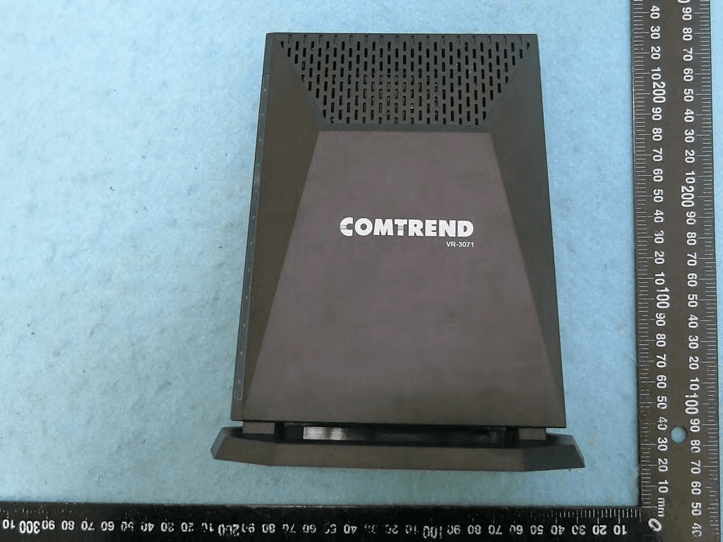
L9VVR3071
Jan 21, 2020Home Gateway
Equipment Class
DTS - Digital Transmission System