LBBGH3000ATA2.4GHz 40 Channel Analog Modulation Cordless Phone
Continental Conair Limited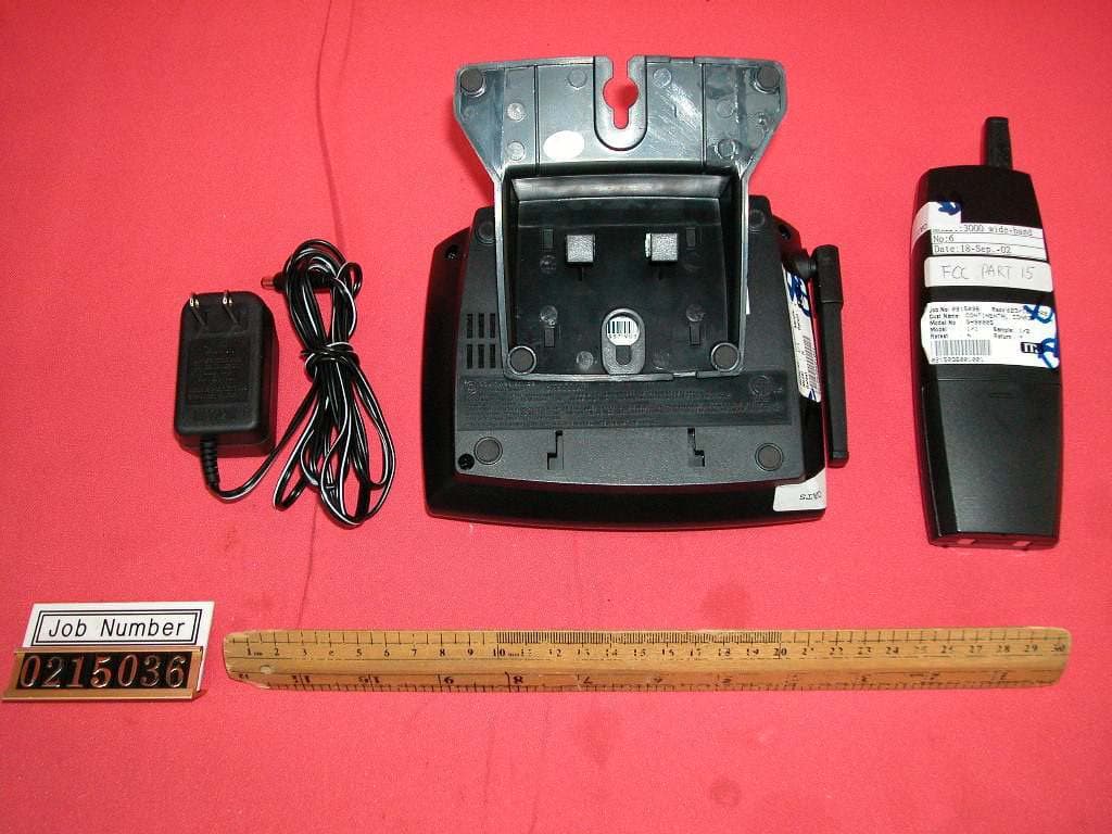
Click to zoom
Application Details
- Equipment Class
- DXT - Part 15 Low Power Transceiver, Rx Verified
- Date of Grant
- Feb 21, 2003
- Application Purpose
- Original Equipment
- Date of Application
- Feb 21, 2003
- Equipment Note
- 2.4GHz 40 Channel Analog Modulation Cordless Phone
- Frequency Range
- 2474.00000000 - 2475.95000000
- Company
- Continental Conair Limited
- Country
- Hong Kong
Documents & Files
Document Text
Text extracted from the exhibit documents filed with the FCC. Open a document above to read the original.
Users Manual
IMPORTANT SAFETY INSTRUCTIONS BEFORE USING YOUR TELEPHONE EQUIPMENT, BASIC SAFETY PRECAUTIONS SHOULD ALWAYS BE FOLLOWED TO REDUCE THE RISK OF FIRE, ELECTRIC SHOCK AND INJURY TO PERSONS, INCLUDING THE FOLLOWING: 1.Read and understand all instructions. 2.Follow all warnings and instructions marked on the product. 3.Unplug this product from the wall telephone jack and power outlet before cleaning. Do not use liquid cleaners or aerosol cleaners. Use damp cloth for cleaning. 4.Do not use this product near water; for example, near a bathtub, wash bowl, kitchen sink, laundry tub, swimming pool, or in a wet basement. 5.Do not place this product on an unstable cart, stand or table. The product may fall, causing serious damage to the product. 6.Slots or openings in the cabinet and the back and bottom are provided for ventilation, to protect it from overheating. These openings must not be blocked or covered. The openings should never be blocked by placing the product on the bed, or other similar surface. This product should never be placed near or over a radiator or heat register. This product should not be placed in a built-in installation unless proper ventilation is provided. 7.This product should be operated only from the type of power source indicated on the marking label. If you are not sure of the type of power supply to your home, consult your dealer or local power company. 8.Do not allow anything to rest on the power cord. Do not locate this product where the cord will be damaged by persons walking on it. 9.Do not overload wall outlets extension cords, as this can result in fire or electric shock. 10.Never push objects of any kind into this product through cabinet slots, as they may touch dangerous voltage points or short out parts. This could result in fire or electric shock. Never spill liquid of any kind on this product. 11.To reduce the risk of electric shock, do not disassemble this product. Instead, when some repair work is required, take the unit to a qualified technician. Opening or removing covers may expose you to dangerous voltages or other risks. Incorrect reassembly can cause electric shock when the appliance is subsequently used. 12.Unplug this product from the wall outlet and refer servicing to qualified service personnel under the following conditions: a. When the power supply cord or plug is damaged or frayed. b. If liquid has been spilled into the product. c. If the product has been exposed to rain or water. d. If the product does not operate normally and proper operating instructions have been followed, adjust only those controls that are covered by the operating instructions. Improper adjustment of other controls may result in damage and will often require extensive work by a qualified technician to restore the product to normal operation. e. If the product has been dropped or cabinet has been damaged. f. If the product exhibits a distinct change in performance. 13.Avoid using telephone (other than a cordless type) during an electrical storm. There may be a remote risk of electrical shock from lightning. 14.Do not use the telephone to report a gas leak in the vicinity of the leak. 15.Use only the power cord and batteries indicated in this manual. Do not dispose of batteries in a fire. They may explode. Check with local codes for possible special disposal instructions. CAUTION Danger of explosion if battery is incorrectly replaced. Replace only with the same or equivalent type recommended by the manufacturer. Dispose of used batteries according to the manufacturer’s instructions. SAVE THESE INSTRUCTIONS SAFETY INSTRUCTIONS FOR BATTERIES CAUTION: To reduce the risk of fire or personal injury, read and follow these instructions.: CONTAINS NICKEL-CADMIUM BATTERY. BATTERY MUST BE RECYCLED OR DISPOSED OF PROPERLY. 1. Use only a Southwestern Bell Freedom Phone®approved battery pack in the handset of your cordless telephone. FOR HANDSET UNIT: a. GP40AAK3BMX 3.6V 400mAHr GPI International Ltd. or b. D-2/3AA400x3 3.6V 400mAHr., BYD Battery Co. Ltd. 2. Do not open or mutilate the battery. Released electrolyte is corrosive and may cause damage to the eyes and skin. It may be toxic if swallowed. 3. Exercise care in handling batteries in order not to short the battery with conducting materials such as rings, bracelets and keys. The battery or conduction material may overheat and cause burns. 4. Charge the battery (ies) provided with or identified for use with this product only in accordance with the instructions and limitations specified in this manual. 5. Observe proper polarity orientation between the Battery Pack and battery charger. The EPA certified RBRC ® * Battery Recycling Seal on the nickel-cadmium (Ni- Cd) battery indicates that Southwestern Bell Freedom Phone® Retail Salesis voluntarily participating in an industry program to collect and recycle these batteries at the end of their useful life, when taken out of service in the United States or Canada. The RBRC ® program provides a convenient alternative to placing used Ni-Cd batteries into the trash or the municipal waste stream, which may be illegal in your areas. Please call 1- 800-8-BATTERY for information on Ni-Cd battery recycling and disposal bans / restrictions in your area. Southwestern Bell Freedom Phone® Retail Salesinvolvement in this program is part of our commitment to preserving our environment and conserving our natural resources. *RBRC ® is a registered trademark of the Rechargeable Battery Recycling Corporation. FCC WANTS YOU TO KNOW This equipment compiles with Part 68 of the FCC rules and ACTA technical requirements. On the bottom of the base of this equipment is a label that contains, among other information, the FCC Registration Number, Ringer Equivalence Number (REN) and the Universal Service Order Code (USOC), which is RJ-11C, for this equipment. You must, upon request, provide this information to your telephone company. An FCC compliant telephone cord and modular plug is provided with this equipment.…
Text truncated - open the document above for the full version.
Users Manual
FCC WANTS YOU TO KNOW This equipment compiles with Part 68 of the FCC rules and ACTA technical requirements. On the bottom of the base of this equipment is a label that contains, among other information, the FCC Registration Number, Ringer Equivalence Number (REN) and the Universal Service Order Code (USOC), which is RJ-11C, for this equipment. You must, upon request, provide this information to your telephone company. An FCC compliant telephone cord and modular plug is provided with this equipment. This equipment is designed to be connected to the telephone network or premises wiring using a compatible modular jack which is TIA/EIA-IS-968 compliant. See Installation Instructions for details. The REN is useful to determine the quantity of devices you may connect to your telephone line and still have all of those devices ring when your telephone number is called. In most, but not all areas, the sum of the REN’s of all devices connected to one line should not exceed five (5.0). To be certain of the number of devices you may connect to your line, as determined by the REN, you should contact your local telephone company to determine the maximum REN for your calling area. If your telephone equipment causes harm to the telephone network, the telephone company may discontinue your service temporarily. If possible, they will notify you in advance. But if advance notice isn’t practical, you will be notified as soon as possible. You will be informed of your right to file a complaint with the FCC. Your telephone company may make changes in its facilities, equipment, operations, or procedures that could affect the proper functioning of your equipment. If they do, you will be notified in advance to give you an opportunity to maintain uninterrupted telephone service. If you experience trouble with this telephone equipment, disconnect from the network until the problem has been corrected or until you are sure that the equipment is not malfunctioning. This equipment may not be used on coin service provided by the telephone company. Connection to party lines is subject to state tariffs. This equipment is hearing aid compatible. WARNING: Changes or modifications to this unit not expressly approved by the party responsible for compliance could void the user’s authority to operate the equipment. NOTE:This equipment has been tested and found to comply with the limits for a Class B digital device, pursuant to Part 15 of the FCC Rules. These limits are designed to provide reasonable protection against harmful interference in a residential installation. Some cordless telephones operate at frequencies that may cause interference to nearby TV’s and VCR’s. To minimize or prevent such interference, the base of the cordless telephone should not be placed near or on top of a TV or VCR. If interference is experienced, moving the cordless telephone farther away from the TV or VCR will often reduce or eliminate the interference. However, there is no guarantee that interference wi occur in a particular installatio this equipment does cause ha interference to radio or telev reception, which can be determ by turning the equipment off an the user is encouraged to t correct the interference by on more of the following measures • Reorient or relocate the rece antenna. • Increase the separation bet the equipment and receiver. • Connect the equipment int outlet on a circuit different that to which the receiv connected. • Consult the dealer or experienced radio TV techn for help. This Southwestern Bell Freedom Phone®is warranted to the original purchaser to be free from defects in materials and workmanship under normal installation, use, and service for a period of one (1) year from the date of purchase as shown on the purchaser’s receipt. The obligation of Southwestern Bell Freedom Phone®Retail Sales under this warranty shall be limited to repair or replacement (at our option) during the warranty period of any part which proves defective in material or workmanship under normal installation, use, and service, provided the product is returned to Southwestern Bell Freedom Phone® Retail Sales TRANSPORTATION CHARGES PREPAID (California residents call 1- 800-366-0937 for shipping instructions). If we choose to replace your Southwestern Bell Freedom Phone® product, the replacement will be warranted for either (a) 90 days or (b) the remainder of the original one year warranty period, whichever is longer. Battery packs are warranted for the same period. Products returned to us must be accompanied by a copy of the purchase receipt. In the absence of such purchase receipt, the warranty period shall be one (1) year from the date of manufacture. To obtain service under this warranty, return the defective product to the service center nearest you together with your sales slip and $9.50 for postage and handling (California residents need only provide proof of purchase). This warranty shall be invalid if the product is damaged as a result of defacement, misuse, abuse, neglect, accident, destruction, or alteration of the serial number, improper electrical voltages or currents, repair alteration or maintenance by any person or party other than our own service facility or an authorized Service Center, or any violation of instructions furnished by us. This warranty is also rendered invalid if this product is removed from the country in which it was purchased, if it is used in a country which it is not registered for use, or if it is used in a country for which it was not designed. Due to variations in telephone systems and communications laws, this product may be illegal for use in some countries. Southwestern Bell Freedom Phone®Retail Sales assumes no responsibility for damages or penalties incurred resulting from the use of this product in a manner or location other than that from which it is intended. This one-year limited warranty is in lieu of all other express warranties, obligations, or liabilities. ANY IMPLIED WARRANTIES, OBLIGATIONS, OR L…
Text truncated - open the document above for the full version.
External Photos
External photos FCC ID: LBBGH3000ATA External photos FCC ID: LBBGH3000ATA
ID Label/Location Info
GH3000 12/09/2002 P/T TEL LINE DC9V 200mA DC9V200mA USE ONLY WITH CLASS 2 POWER SOURCE USEONLYWITH CLASS 2POWERSOURCE FCC ID: LBBGH3000ATA Model No. GH3000AT V01A AT 0302 S/N:CXXXXXX US ® L I S T E D L I S T E D 70255 PRIVACY OF COMMUNICATIONS MAY NOT BE ENSURED WHEN USING THIS PHONE. FCC ID : LBBGH3000ATA THIS DEVICE COMPLIES WITH PART 15 OF THE FCC RULES. OPERATION IS SUBJECT TO THE FOLLOWING TWO CONDITIONS: (1) THIS DEVICE MAY NOT CAUSE HARMFUL INTERFERENCE, AND (2) THIS DEVICE MUST ACCEPT ANY INTERFERENCE RECEIVED, INCLUDING INTERFERENCE THAT MAY CAUSE UNDESIRED OPERATION. CONFORMS TO ANSI/UL STD. 1950 Southwestern Bell ® Complies with 47 CFR Part 68 requirements REGISTRATION NUMBER: US: SBFW909BGH3000AT USOC JACK: RJ11CREN: 0.9B HAC MADE IN CHINA MANUFACTURED TO BELL SPECIFICATIONS MODEL No. GH3000AT
Internal Photos
Internal photos FCC ID: LBBGH3000ATA Base assembly (View 1) Base assembly (View 2) Internal photos FCC ID: LBBGH3000ATA Base Main PCB comp side (view 1) Base Main PCB comp side (view 2) Internal photos FCC ID: LBBGH3000ATA Base Main PCB solder side Base Oscillator PCB comp side Internal photos FCC ID: LBBGH3000ATA Base Oscillator PCB solder side Internal photos FCC ID: LBBGH3000ATA Handset assembly Handset Main PCB comp side (View 1) Internal photos FCC ID: LBBGH3000ATA Handset Main PCB comp side (View 2) Handset Main PCB solder side Internal photos FCC ID: LBBGH3000ATA Handset PCB keypad side Handset PCB keypad rear side (View 1) Internal photos FCC ID: LBBGH3000ATA Handset PCB keypad rear side (View 2) Handset Oscillator PCB comp side Internal photos FCC ID: LBBGH3000ATA Handset Oscillator PCB solder side
Operational Description
GH3000 Circuit Description 1. Introduction The model GH3000 is a 40 channel (2.40255-2.47595GHz) cordless telephone. The whole unit is divided into two main parts as follow : a. A remote Handset. b. A Base unit. 2. Functional Blocks of the Remote Handset 2.1 Keyboard matrix and function LED 2.2 MCU and MCU interface 2.3 Antenna and RF module 2.4 Compander 2.5 Data shaper 2.6 Charge detector 2.7 Low battery detector 2.8 Buzzer amplifier 3. Circuit Block Description 3.1 Keyboard matrix and function LED Pin 4 to pin7, pin 10 to pin 11 and pin 25 of the U2 MCU form a keyboard, and the talk LED is controlled by the pin 12 of the MCU. 3.2 MCU and MCU interface The handset and the base is link up by the pins(9,24 in HS and 21,24 in Base). Besides, the PLL of the RF Module is controlled by the pins 15,17 and 18 of the MCU. 3.3 Antenna and RF module ANT is the common point for transmitting and receiving through antenna. MD1 is a RF module which consists of Duplexer, Power amplifier, Mixer & IF, RXVCO, TXVCO, VCC & TXVCC control, Synthesizer and DEMO Audio Output circuits. RF module circuit can be described as followings: 3.4.1 Power Supply 3.4.2 PLL and MCU Interface 3.4.3 RF Transmitter 3.4.4 RF Receiver 3.4.5 Audio Detector 3.4.1 Power Supply The RF transmitter receives power from TXVCC. TXVCC is enabled only during TALK mode.The RF receiver receives power from RXVCC. RXVCC is enabled only during TALK or stand-by mode when wake up. 3.4.2 PLL and MCU Interface The frequencies of the RF transmitter and RF local oscillator are controlled by PLL IC U1. The MCU transmit PLL data through DATA, CLK and CE signal lines. The basic clock frequency of the PLL is derived from an 11.15MHz crystal inside the RF module. The local frequencies to TX and RX are generated and locked at 825MHz and 798MHz respectively. 3.4.3 RF Transmitter The RF transmitter oscillator frequency 825MHz is controlled by the PLL through Vt. The PLL samples the RF frequency through fin. The audio input signal AFIN is fed to this RF oscillator through the FM modulator. Fundamental frequency 825MHz is multiplied to 2475MHz and bypass through band pass filter formed by Q7, ML5, C5, C37 and ML4. The filtered 2475MHz is then injected into TX power amplifier Q6 and related passive components. The enlarged 2475MHz rf signal is then input into the 2475MHz TX_FILTER, DF1. The transmitted rf signal is then injected into the ANTENNA and radiated out into air. 3.4.4 RF Receiver Received rf signal is collected from ANTENNA and passed through 2403MHz filter DF2. The filtered 2403MHz rf signal will then be injected into the LNA Q3 and be enlarged. The amplified 2403MHz signal is then input into the MIXER which is formed by Q4 and related passive components. Q2 and VD2 with related resistors and capacitors network form the RXVCO which is fed and locked by the PLL U1. The fundamental 798MHz frequency is multiplied to 2393MHz and bypass the BPF formed by C28, ML11, C26, C25, ML13 and C 50 to the receiver mixer. The receiver local oscillator frequency is controlled by the PLL through Vt. The PLL samples the local oscillator RF frequency through fin. The mixer collects the input from LNA and 2393MHz signal from BPF and then output the IF 10.7MHz into Q5. 3.4.5 Audio Detector Amplified IF from Q5 is passed into 10.7MHz filter CF1,amplifier Q8 , 10.7MHz filter CF3 and then injected into the IF demodulated IC U4. Detected audio will then be recovered and output at the AFOUT pin of the RF module. 3.4 Compander A compander U3 is used for improving the S/N of the transmit and receive audio signal. 3.5 Data shaper The information which sending from base unit, is recovered by the amplifier Q1 and Q2. 3.6 Charge detector ZD1, D4, D5, D6, D7, D8, R53, C29 form a charge detector to direct the charging signal to the MCU pin 26. 3.7 Low battery detector A battery low detector is built-in by Q3 which detects the battery dropping and sends a signal to pin 19 of MCU. 3.8 Buzzer amplifier Q11 is a buzzer amplifier driven directly by the MCU pin 21,22 and 23. 4. Functional Blocks of the Base unit 4.1 Power supply 4.2 MCU and MCU interface 4.3 Antenna and RF module 4.4 Compander 4.5 Data shaper 4.6 Charge detector 4.7 Line audio interface 4.8 Ring detector 4.9 Led function board 4.10 Noise detector and carrier detector 5. Circuit Block Description 5.1 Power supply BQ4 8050 regulateS the input DC 9V to 5V which provides power to every part of the circuit. 5.2 MCU and MCU interface The heart of the base is BU5 MCU that communicates with the PLL of BMD1 through pins 5,6 and 7. Transmitter is controlled by the signal TX_DC which output from MCU via pin 20. MCU pins 6 to 11 consist of a resistor ladder for generating DTMF signal. The communication between Handset and Base is via the pin 24 and pin 26 through the RF link. 5.3 Antenna and RF modulator ANT is antenna transmit and receive signal. BMD1 is a RF modulator which consist of Duplexer, Power amplifier, Mixer & IF, RXVCO, TXVCO, VCC & TXVCC control, Synthesizer and DEMO Audio Output circuits. The block diagram of RF Module is as shown below. It is made up of the following parts: 5.4.1 Power Supply 5.4.2 PLL and MCU Interface 5.4.3 RF Transmitter 5.4.4 RF Receiver 5.4.5 Audio Detector 5.4.1 Power Supply The RF transmitter receives power from TXVCC. TXVCC is enabled only during TALK mode or Ring mode. The RF receiver receives power from RXVCC. RXVCC is enabled when BASE plug in DC adapter. 5.4.2 PLL and MCU Interface The frequencies of the RF transmitter and RF local oscillator are controlled by PLL IC U1. The MCU transmit PLL data through DATA, CLK and CE signal lines. The basic clock frequency of the PLL is derived from an 11.15MHz crystal inside the RF module. The local frequencies to TX and RX are generated and locked at 801MHz and 828MHz respectively. 5.4.3 RF Transmitter The RF transmitter oscillator frequency 801MHz is controlled by the PLL through Vt. The PLL samples the RF frequency through fin. The audio input sign…
Text truncated - open the document above for the full version.
Test Report
• The test results reported in this report shall refer only to the sample actually tested and shall not refer or be deemed to refer to bulk from which such a sample may be said to have been obtained. • This report shall not be reproduced except in full without prior authorization form Intertek Testing Services Limited FCC ID: LBBGH3000ATA Intertek Testing Services Hong Kong Ltd. 2/F., Garment Centre, 576 Castle Peak Road, Kowloon, Hong Kong. Tel: (852) 2173 8888 Fax: (852) 2741 1693 Continental Conair Limited Application For Certification 2.4GHz 40 Channel Analog Modulation Cordless Phone (FCC ID: LBBGH3000ATA) WO# 0215036 TL/Ann Choy January 9, 2003 INTERTEK TESTING SERVICES FCC ID: LBBGH3000ATA i LIST OF EXHIBITS INTRODUCTION EXHIBIT 1: General Description EXHIBIT 2: System Test Configuration EXHIBIT 3: Emission Results EXHIBIT 4: Equipment Photographs EXHIBIT 5: Product Labelling EXHIBIT 6: Technical Specifications EXHIBIT 7: Instruction Manual EXHIBIT 8: Security Code Information INTERTEK TESTING SERVICES FCC ID: LBBGH3000ATA ii MEASUREMENT/TECHNICAL REPORT Continental Conair Limited - MODEL: GH3000S(xxxxx), GH3000(xxxxx), GH3000AT(xxxxx) FCC ID: LBBGH3000ATA This report concerns (check one:) Original Grant X Class II Change Equipment Type : Cordless Telephone (example : computer, modem, transmitter, etc.) Deferred grant requested per 47 CFR 0.457(d)(1)(ii)? Yes No X If yes, defer until : date Company Name agrees to notify the Commission by: date of the intended date of announcement of the product so that the grant can be issued on that date. Transition Rules Request per 15.37 ? Yes No X If no, assumed Part 15, Subpart C for intentional radiator - the new 47 CFR [12-18-01 Edition] Provision. Report prepared by: Tommy Leung Intertek Testing Services. 2/F., Garment Centre, 576 Castle Peak Road, Kowloon, Hong Kong. Phone : 852-2173-8538 Fax: 852-2741-1693 INTERTEK TESTING SERVICES FCC ID: LBBGH3000ATA iii Table of Contents 1.0 General Description.........................................................................................................2 1.1 Product Description.........................................................................................................2 1.2 Related Submittal(s) Grants ............................................................................................3 1.3 Test Methodology ............................................................................................................3 1.4 Test Facility .....................................................................................................................3 2.0 System Test Configuration .................................................................................................5 2.1 Justification ......................................................................................................................5 2.2 EUT Exercising Software................................................................................................5 2.3 Support Equipment List and Description........................................................................6 2.4 Measurement Uncertainty ...............................................................................................7 2.5 Equipment Modification..................................................................................................7 3.0 Emission Results ...................................................................................................................9 3.1 Field Strength Calculation .............................................................................................10 3.2 Radiated Emission Configuration Photograph - Base Unit ..........................................11 3.3 Radiated Emission Data - Base Unit .............................................................................12 3.4 Radiated Emission Configuration Photograph - Handset .............................................15 3.5 Radiated Emission Data - Handset................................................................................16 3.6 Radiated Emission on the bandedge..............................................................................19 3.7 Line Conducted Configuration Photograph - Base Unit...............................................21 3.8 Line Conducted Emission Data - Base Unit .................................................................22 4.0 Equipment Photographs ...................................................................................................25 5.0 Product Labelling ...............................................................................................................27 6.0 Technical Specifications ....................................................................................................29 7.0 Instruction Manual ............................................................................................................31 8.0 Security Code Information ...............................................................................................33 INTERTEK TESTING SERVICES FCC ID: LBBGH3000ATA iv List of attached file Exhibit type File Description filename Test Report Test Report report.doc Operation Description Technical Description descri.pdf Test Setup Photo Radiated Emission for Base config photos.doc Test Setup Photo Radiated Emission for Handset config photos.doc Test Report Emission Plot emission.pdf Test Setup Photo Conducted Emission config photos.doc Test Report Conducted Emission Test Result conduct.pdf External Photo External Photo external photos.doc Internal Photo Internal Photo internal photos.doc Block Diagram Block Diagram block.pdf Schematics Circuit Diagram circuit.pdf ID Label/Location Label Artwork and Location label.pdf User Manual User Manual manual.pdf User Manual FCC Information fcc information.pdf INTERTEK TESTING SERVICES FCC ID: LBBGH3000ATA 1 EXHIBIT 1 GENERAL DESCRIPTION INTERTEK TESTING SERVICES FCC ID: LBBGH3000ATA 2 1.0 …
Text truncated - open the document above for the full version.
Test Report
Intertek Testing Services ETL SEMKO Report No.:0215036 Talk Mode Ctrl No.:N/A PAGE 1 Tested By:Hong, Report No.:0215036 Scan Settings (1 Range) |--------- Frequencies -----------||----------- Receiver Settings ------------| Start Stop Step IF BW Detector M-Time Atten Preamp OpRge 450k 30M 5k 10k PK 20ms AUTO LN OFF 60dB Final Measurement: x QP Meas Time: 1 s Subranges: 16 Acc Margin: 20dB Transducer No. Start Stop Name 21 9k 30M EW0698 0 10 20 30 40 50 60 70 dBuV 80 0.45 30 MHz 110 FCC15B Intertek Testing Services ETL SEMKO Report No.:0215036 Talk Mode Ctrl No.:N/A Tested By:Hong, Report No.:0215036 Scan Settings (1 Range) |--------- Frequencies -----------||----------- Receiver Settings ------------| Start Stop Step IF BW Detector M-Time Atten Preamp OpRge 450k 30M 5k 10k PK 20ms AUTO LN OFF 60dB Final Measurement Results: no Results
Test Setup Photos
The Worst Case Configuration Photographs FCC ID: LBBGH3000ATA Radiated Emission – Base Front View Rear View The Worst Case Configuration Photographs FCC ID: LBBGH3000ATA Radiated Emission – Handset Front View Rear View The Worst Case Configuration Photographs FCC ID: LBBGH3000ATA Conducted Emission Front View Rear View The Worst Case Configuration Photographs FCC ID: LBBGH3000ATA Conducted Emission Side View
Test Setup Photos
The Worst Case Configuration Photographs FCC ID: LBBGH3000ATA Radiated Emission – Base Front View Rear View The Worst Case Configuration Photographs FCC ID: LBBGH3000ATA Radiated Emission – Handset Front View Rear View The Worst Case Configuration Photographs FCC ID: LBBGH3000ATA Conducted Emission Front View Rear View The Worst Case Configuration Photographs FCC ID: LBBGH3000ATA Conducted Emission Side View
Test Setup Photos
The Worst Case Configuration Photographs FCC ID: LBBGH3000ATA Radiated Emission – Base Front View Rear View The Worst Case Configuration Photographs FCC ID: LBBGH3000ATA Radiated Emission – Handset Front View Rear View The Worst Case Configuration Photographs FCC ID: LBBGH3000ATA Conducted Emission Front View Rear View The Worst Case Configuration Photographs FCC ID: LBBGH3000ATA Conducted Emission Side View
Contact Information
Applicant
David Ng(Manager, Consumer Electronics)
852 2751 4688Fax: 852 2751 8920
Technical Contact
Intertek Testing Services Hong Kong Ltd.Tommy Leung
[email protected]852-2173-8538
2/F., Garment Centre, · Kowloon, · Hong Kong
Non-Technical Contact
Intertek Testing Services Hong Kong Ltd.Tommy Leung
[email protected]852-2173-8538
Test Firm
Intertek Testing Services Hong KongBilly Chow
Technical Specifications
| # | Rule Parts | Frequency Range | Power Output |
|---|---|---|---|
| 2 | 15C | 2.47 GHz - 2.48 GHz | - |
Other Applications from Continental Conair Limited
LBBGH3128AT
Jul 25, 20042.4GHz 40 Channel Cordless Phone w/ CID
Equipment Class
DXT - Part 15 Low Power Transceiver, Rx Verified
LBBGH3100H
May 06, 2004Cordless Phone
Equipment Class
DXX - Part 15 Low Power Communication Device Transmitter
LBBGH3100
May 06, 2004Cordless Phone
Equipment Class
DXX - Part 15 Low Power Communication Device Transmitter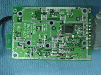
LBBGH3062
Apr 25, 20042.4 GHz Cordless Phone with Radio
Equipment Class
DXX - Part 15 Low Power Communication Device Transmitter
LBBGH4100
Apr 05, 20042.4GHz FHSS Cordless Phone w/ CID
Equipment Class
DSS - Part 15 Spread Spectrum Transmitter