LBBGH3034AT2.4 GHz 40 Channel Cordless Phone with Caller ID
Continental Conair Limited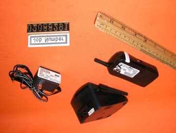
Click to zoom
Application Details
- Equipment Class
- DXT - Part 15 Low Power Transceiver, Rx Verified
- Date of Grant
- Sep 05, 2002
- Application Purpose
- Original Equipment
- Date of Application
- Sep 05, 2002
- Equipment Note
- 2.4 GHz 40 Channel Cordless Phone with Caller ID
- Frequency Range
- 2474.00000000 - 2475.95000000
- Company
- Continental Conair Limited
- Country
- Hong Kong
Documents & Files
Document Text
Text extracted from the exhibit documents filed with the FCC. Open a document above to read the original.
Users Manual
STOP ...DON’T TAKE ME BACK TO THE STORE. LOOK ...FOR THE TOLL-FREE “HELP” TELEPHONE NUMBER. LISTEN ...AS THE EXPERTS TALK YOU THROUGH THE PROBLEM. For immediate answers to your questions regarding operation, missing parts or installation, call the SOUTHWESTERN BELL FREEDOM PHONE® RETAIL SALES HELP LINE AT: 1-800-366-0937 Monday - Friday 8:30a.m. - 9:00p.m. EST Saturday 8:30a.m. - 12:30p.m. EST http://www.swbfreedomphone.com SOUTHWESTERN BELL FREEDOM PHONE® 7475 N. Glen Harbor Blvd., Glendale, AZ 85307 GH3034AT Printed in China Southwestern BellFreedom Phone ® 2.4GHz Cordless Telephone with Call Waiting Caller IDGH3034AT Owner’s ManualToll Free Helpline 1-800-366-0937http://www.swbfreedomphone.com IB- XXXX CONTENTS IMPORTANT SAFETY INSTRUCTIONSSAFETY INSTRUCTIONS FOR BATTERIESNAME OF CONTROLS AND INDICATIONSFCC WANTS YOU TO KNOWINTRODUCTIONFEATURESBOX CONTENTSPREPARATIONOPERA TING INSTRUCTIONS INSTALLATIONHANDSET BATTERY CHARGINGCALLER ID SETUPTELEPHONE OPERATIONCALLER ID OPERATIONTROUBLESHOOTINGPRODUCT CARESERVICELIMITED WARRANTY 2 34589 1010111213141821232425 IMPORTANT SAFETY INSTRUCTIONS BEFORE USING YOUR TELEPHONE EQUIPMENT, BASIC SAFETY PRECAUTIONSSHOULD ALWAYS BE FOLLOWED TO REDUCE THE RISK OF FIRE, ELECTRIC SHOCKAND INJURY TO PERSONS, INCLUDING THE FOLLOWING:1. Read and understand all instructions.2. Follow all warnings and instructions marked on the product.3. Unplug this product from the wall telephone jack and power outlet before cleaning. Donot use liquid cleaners or aerosol cleaners. Use a damp cloth for cleaning.4. Do not use this product near water, for example, near a bath tub, wash bowl, kitchensink, laundry tub, swimming pool, or in a wet basement.5. Do not place this product on an unstable cart, stand or table. The product may fall,causing serious damage.6. Slots or openings in the cabinet and the back and bottom are provided for ventilation, toprotect it from overheating. These openings must not be blocked or covered. The openingsshould never be blocked by placing the product on a bed, or other similar surface. This productshould never be placed near or over a radiator or heat register.7. This product should be operated only from the type of power source indicated on themarking label. If you are not sure of the type of power supply to your home, consult yourdealer or local power company.8. Do not allow anything to rest on the power cord. Do not place this product where thecord will be damaged by persons stepping on it. 9. Do not overload wall outlets and extension cords, as this can result in fire or electric shock. 10. Never push objects of any kind into this product through cabinet slots, as they maytouch dangerous voltage points or short out parts. This could result in fire or electric shock.Never spill liquid of any kind on the product.11. To reduce the risk of electric shock, do not disassemble this product. Instead, when serviceor repair work is required, take it to a qualified service technician. Opening or removing coversmay expose you to dangerous voltages or other risks. Incorrect reassembly can cause electricshock when the appliance is subsequently used.12. Unplug this product from the wall outlet and refer servicing to qualified service personnelunder the following conditions: a. When the power supply cord or plug is damaged or frayed.b. If liquid has been spilled into the product.c. If the product has been exposed to rain or water.d. If the product does not operate normally, and proper operating instructions have been followed, adjust only those controls that are covered by the operating instructions. Improperadjustment of other controls may result in damage and will often require extensive work by aqualified technician to restore the product to normal operation. e. If the product has been dropped or the cabinet has been damaged.f. If the product exhibits a distinct change in performance. 13. Avoid using a telephone (other than a cordless type) during an electrical storm. Theremay be a remote risk of electric shock from lightning.14. Do not use the telephone to report a gas leak in the vicinity of the leak.15. Use only the power cord and batteries indicated in this manual. Do not dispose of batteriesin a fire. They may explode. Check with local codes for possible special disposal instructions. CAUTIONDanger of explosion if battery is incorrectly replaced.Replace only with the same or equivalent type recommended by the manufacturer.Dispose of used batteries according to the manufacturer’s instructions. 3 4 SAFETY INSTRUCTIONS FOR BATTERIES Safety Instructions for BatteriesHandset Battery PackCAUTION:Use only a Southwestern Bell Freedom Phone® approved battery pack in the handsetof your Cordless Telephone. To reduce the risk of fire or injury, always do the followingwhen replacing, discarding or charging batteries. When handling the batteries, becareful not to short the battery with conducting materials such as rings, bracelets, andkeys. The battery or conducting material may overheat and cause burns.Use only the following type and size of battery pack:FOR HANDSET UNIT : GP35AAAK3BMX 3.6V 350mAHr, GPI International Ltd a. Do not dispose of the battery pack in a fire. The cell may explode. Check with local codes for possible special disposal instructions. b. Do not attempt to open or mutilate the battery pack. The chemicals are dangerous and may cause damage to the eyes or skin, and may be toxic if swallowed. c. Follow the charge instructions outlined in this manual. (See page 12) The EPA certified RBRC®* Battery Recycling Seal on the nickel-cadmium (Ni-Cd)battery indicates that Southwestern Bell Freedom Phone® Retail Sales is voluntarilyparticipating in an industry program to collect and recycle these batteries at the end oftheir useful life, when taken out of service in the United States or Canada. The RBRC®program provides a convenient alternative to placing used Ni-Cd batteries into thetrash or the municipal waste stream, which may be illegal in your areas…
Text truncated - open the document above for the full version.
Users Manual
FCC WANTS YOU TO KNOW This equipment complies with Part 68 of the FCC rules and ACTA technicalrequirements. On the bottom of the base of this equipment is a label that contains,among other information, the FCC Registration Number and Ringer EquivalenceNumber (REN) for this equipment. You must, upon request, provide this information toyour telephone company.An FCC compliant telephone cord and modular plug is provided with this equipment.This equipment is designed to be connected to the telephone network or premises wiringusing a compatible modular jack which is TIA/EIA-IS-968 compliant. See InstallationInstructions for details.The REN is useful to determine the quantity of devices you may connect to yourtelephone line and still have all of those devices ring when your telephone number iscalled. In most, but not all areas, the sum of the REN’s of all devices connected to oneline should not exceed five (5.0). To be certain of the number of devices you mayconnect to your line, as determined by the REN, you should contact your localtelephone company to determine the maximum REN for your calling area.If your telephone equipment causes harm to the telephone network, the telephonecompany may discontinue your service temporarily. If possible, they will notify you inadvance. But if advance notice isn’t practical, you will be notified as soon as possible.You will be informed of your right to file a complaint with the FCC.Your telephone company may make changes in its facilities, equipment, operations, orprocedures that could affect the proper functioning of your equipment. If they do, youwill be notified in advance to give you an opportunity to maintain uninterruptedtelephone service. If you experience trouble with this telephone equipment, disconnectfrom the network until the problem has been corrected or until you are sure that theequipment is not malfunctioning.This equipment may not be used on coin service provided by the telephone company.Connection to party lines is subject to state tariffs.The USOC number of the registration jack for the equipment is RJ11C.This equipment is hearing aid compatible.Warning: Changes or modifications to this unit not expressly approved by the party responsible for compliance could void the user’s authority to operate the equipment.NOTE: This equipment has been tested and found to comply with the limits for a Class B digital device, pursuant to Part 15 of the FCC Rules. These limits are designed toprovide reasonable protection against harmful interference in a residential installation.Some cordless telephones operate at frequencies that may cause interference tonearby TV’s and VCR’s. To minimize or prevent such interference, the base of thecordless telephone should not be placed near or on top of a TV or VCR. If interferenceis experienced, moving the cordless telephone farther away from the TV or VCR willoften reduce or eliminate the interference. However, there is no guarantee thatinterference will not occur in a particular installation. If this equipment does causeharmful interference to radio or television reception, which can be determined byturning the equipment off and on, the user is encouraged to try to correct theinterference by one or more of the following measures: • Reorient or relocate the receiving antenna.• Increase the separation between the equipment and receiver.• Connect the equipment into an outlet on a circuit different from that to which the receiver is connected. 9 INTRODUCTION ABOUT THE GH3034The GH3034 is a 2.4GHz Cordless Phone with Caller Identifier. It isdesigned and engineered to exacting standards for reliability, long life,and outstanding performance.FEATURES• Caller ID (64 call data memory locations) with call waiting• 40 Channels (auto or manual selection)• LCD on the handset with three-language selection• 10-Number Two-touch Dial Memory• Direct dialing from caller list• Extended battery life• Digital security codingThe GH3034 features include AutoTalk™ and AutoStandby™.AutoTalk™ allows you to answer a call by just removing the Handsetfrom the Base so you don’t have to waste time pushing buttons orflipping switches. AutoStandby™ allows you to hang up by simplyreturning the handset to the Base.The UltraClear Plus™ true compander circuitry virtually eliminatesbackground noise. This innovative technology, together with 40different channels, provides you with the best possible receptionduring all your conversations.TO PROTECT YOU AGAINST MISBILLED CALLS, THE GH3010 HASRANDOM CODE™ DIGITAL SECURITY WHICH AUTOMATICALLYSELECTS ONE OF OVER 65,000 DIGITAL SECURITY CODES FORTHE HANDSET AND BASE UNIT. ALSO, THE AUTOSECURER™FEATURE ELECTRONICALLY LOCKS YOUR PHONE WHEN THEHANDSET IS IN THE BASE. TO GET THE MOST FROM YOURGH3034, PLEASE READ THIS OPERATING GUIDE THOROUGHLY. 8
External Photos
External photos FCC ID: LBBGH3034AT External photos FCC ID: LBBGH3034AT
ID Label/Location Info
V01A AT 0302 S/N:CXXXXXX US ® L I S T E D L I S T E D 70255 PRIVACY OF COMMUNICATIONS MAY NOT BE ENSURED WHEN USING THIS PHONE. FCC ID : LBBGH3034AT THIS DEVICE COMPLIES WITH PART 15 OF THE FCC RULES. OPERATION IS SUBJECT TO THE FOLLOWING TWO CONDITIONS: (1) THIS DEVICE MAY NOT CAUSE HARMFUL INTERFERENCE, AND (2) THIS DEVICE MUST ACCEPT ANY INTERFERENCE RECEIVED, INCLUDING INTERFERENCE THAT MAY CAUSE UNDESIRED OPERATION. CONFORMS TO ANSI/ UL STD. 1950 Southwestern Bell ® COMPLIES WITH 47 CFR Part 68 REQUIREMENTS REGISTRATION NUMBER: US: SBFW909BGH3034AT USOC JACK: RJ11C REN: 0.9B HAC MADE IN CHINA MANUFACTURED TO BELL SPECIFICATIONS MODEL No. GH3034AT LICENSED UNDER UNITED STATES PATENT NO. 5,263,084 3034BL 06/06/2002 P/T RINGER OFFON TEL LINE DC9V 200mA USE ONLY WITH CLASS 2 POWER SOURCE FCC ID: LBBGH3034AT Model No. GH3034AT
Internal Photos
Internal photosFCC ID: LBBGH3034AT Base assembly Base Main PCB comp side (View 1) Internal photosFCC ID: LBBGH3034AT Base Main PCB comp side (View 2) Base Main PCB solder side Internal photosFCC ID: LBBGH3034AT Base Oscillator PCB co mp side Base Oscillator PCB so lde r side Internal photosFCC ID: LBBGH3034AT Ha ndse t asse mbly Handset Main PCB comp side (View 1) Internal photosFCC ID: LBBGH3034AT Handset Main PCB comp side (View 2) Handset Main PCB display side Internal photosFCC ID: LBBGH3034AT Ha ndse t Oscillato r PCB co mp s ide Ha ndse t Oscillato r PCB solde r side
Operational Description
3034 Circuit Description 1. Introduction The model 3034 is a 40 channel (2.40255-2.47595GHz ) Caller ID cordless telephone. The whole unit is divided into two main parts as follow : a. A remote Handset. b. A Base unit. 2. Functional Blocks of the remote Handset 2.1 Keyboard matrix and function LED 2.2 LCD 2.3 MCU and MCU interface 2.4 Antenna and RF module 2.5 Compander 2.6 Data shaper 2.7 Charge detector 2.8 Low battery detector 2.9 Buzzer amplifier 3. Circuit Block Description of the remote Handset 3.1 Keyboard matrix and function LED Pin 41 to pin 49 of the MCU:U2 NT93420 form a keyboard, and the new call LED is controlled by the pin 59 of the MCU. 3.2 LCD LCD1 is controlled by the MCU: U1 NT93420 pin 1 to pin 29, pin 74 to pin 100. 3.3 MCU and MCU interface The handset and the base is link up by the pins(40,63 in Handset and 43,78 in Base). Besides, the PLL of the RF Module is controlled by the pins 35 to 37 of the MCU . 3.4 Antenna and RF module Antenna used in handset, which are soldered on the RF module of PCB board, is soft wire. In addition, it is integral ANT is the common point for transmitting and receiving through antenna, MD1 is a RF module which consists of Filter, Power amplifier, Mixer & IF, RXVCO, TXVCO, VCC & TXVCC control, Synthesizer and DEMO Audio Output circuits. RF module cirucit can be described as followings: 3.4.1 PLL operation U1 PLL IC gets data from cpu through pins: DATA, CLK and STB. The generated local frequency is driven by crystal 11.15MHz. The local frequencies to TX and RX are generated and locked at 825MHz and 798MHz respectively. 3.4.2 RX VCO and 2393MHz BPF Q2 and VD2 with related resistors and capacitors network form the RXVCO which is fed and locked by the PLL U1. The fundamental 798MHz frequency is multiplied to 2393MHz and bypass the BPF formed by C28, ML11, C26, C25, ML13 and C 50 to the receiver mixer. 3.4.3 TX VCO and modulator with 2475MHz BPF Audio from base band circuit is fed into modulator formed by VD1. Modulated signal is fed into TX VCO which is formed by Q1 and related RC network. The TX VCO is fed and locked by the PLL U1. Fundamental frequency 825MHz is multiplied to 2475MHz and bypass through band pass filter formed by Q7, ML5, C5, C37 and ML4. The filtered 2475MHz is then injected into TX power amplifier Q6. 3.4.4 RF receiving parts Received rf signal is collected from ANTENNA and passed through 2403MHz filter DF2. The filtered 2403MHz rf signal will then be injected into the LNA Q3 and be enlarged. The amplified 2403MHz signal is then input into the MIXER which is formed by Q4 and related passive components. The mixer collects the input from LNA and 2393MHz signal from BPF and then output the IF 10.7MHz into Q5. 3.4.5 Receiving IF and DEMODULATED parts Amplified IF from Q5 is passed into 10.7MHz filter CF1 and then injected into the IF demodulated IC U2. 10.7MHz signal is then mixed with the 11.15MHz frequency in the 2 nd mixer in the IC and then a 450kHz IF is then input into the 450kHz ceramic IF filter CF2. Filtered 450kHz IF is then passed back into the FM detector of the IC U2. Detected audio will then be recovered out from the demodulated IC U2 and output at the AUDIO OUTPUT pin of the RF module. 3.4.6 RF Transmission part 2475MHz filtered signal from 2475MHz filter is input into the TX power amplifier which formed by Q6 and related passive components. The enlarged 2475MHz rf signal is then input into the 2475MHz TX_FILTER, DF1. The transmitted rf signal is then injected into the ANTENNA and radiated out into air. 3.5 Compander A compander U3 is used for improving the S/N of the transmit and receive audio signal. 3.6 Data shaper The information which sending from base unit, is recovered by the amplifier Q1 and Q4, Q5. 3.7 Chargier detector ZD1, R33, C14 and R33 form a charge detector to direct the charging signal to the MCU pin 31. 3.8 Low battery detector A battery low detector is built-in by the Q7, R27, R28, R29 and D3 which detects the battery dropping and sends a signal to pin 32 of MCU. 3.9 Buzzer amplifier Q9 is a buzzer amplifier driven directly by the MCU pin 61. 4. Functional Blocks of the Base unit 4.1 Power supply 4.2 MCU and MCU interface 4.3 Calling line identifier 4.4 Antenna and RF module 4.5 Compander 4.6 Data Shaper 4.7 Charge detector 4.8 Line audio interface 4.9 Ring detector 4.10 Led function board 4.11 Carrier detector 5. Circuit Block Description of Base Unit 5.1 Power supply BU5 7805 regulate the input DC 9V to 5V which provides power to every part of the circuit. 5.2 MCU and MCU interface The heart of the base is MCU BMU1: NT93423 that communicates with the PLL of BMD1 through pins 39,40 and 41. Transmitter is controlled by the signal TX_DC which output from MCU via pin 53. MCU pin 95 is for generating DTMF signal. The communication between Handset and Base is via the pin 43 and pin 78 through the RF link. 5.3 Calling line identifier MCU pin 87 to pin 88, when receiving caller ID data, MCU controls the LCD to display the correct information. 5.4 Antenna and RF modulator Antenna used in base unit, which are soldered on the RF module of PCB board, is soft wire. In addition, it is integral ANT is antenna transmit and receive signal. BMD1 is a RF modulator which consist of Filter, Power amplifier, Mixer & IF, RXVCO, TXVCO, VCC & TXVCC control, Synthesizer and DEMO Audio Output circuits. 5.4.1 PLL operation U1 PLL IC gets data from cpu through pins: DATA, CLK and STB. The generated local frequency is driven by crystal 11.15MHz. The local frequencies to TX and RX are generated and locked at 801MHz and 828MHz respectively. 5.4.2 RX VCO and 2485MHz BPF Q2 and VD2 with related resistors and capacitors network form the RXVCO which is fed and locked by the PLL U1. The fundamental 8281MHz frequency is multiplied to 2485MHz and bypass the BPF formed by C28, ML11, C26, C25, ML13 and C50 to the receiver mixer. 5.4.3 TX VCO and modulator with 2403MHz BPF Audio from base band circuit is fed into modulator formed b…
Text truncated - open the document above for the full version.
Test Setup Photos
The Worst Case Configuration Photographs FCC ID: LBBGH3034AT Radiated Emission – Base Front View Re ar Vie w The Worst Case Configuration Photographs FCC ID: LBBGH3034AT Radiated Emission – Handset Front View Re ar Vie w The Worst Case Configuration Photographs FCC ID: LBBGH3034AT Conducted Emission Front View Re ar Vie w The Worst Case Configuration Photographs FCC ID: LBBGH3034AT Conducted Emission Side View
Contact Information
Applicant
David Ng(Manager, Consumer Electronics)
852 2751 4688Fax: 852 2751 8920
Technical Contact
Intertek Testing Services Hong Kong Ltd.Tommy Leung
[email protected]852 2173 8538
2/F., Garment Centre · Kowloon · Hong Kong
Non-Technical Contact
Intertek Testing Services Hong Kong Ltd.Tommy Leung
[email protected]852 2173 8538
Test Firm
Intertek Testing Services Hong KongBilly Chow
Technical Specifications
| # | Rule Parts | Frequency Range | Power Output |
|---|---|---|---|
| 2 | 15C | 2.47 GHz - 2.48 GHz | - |
Other Applications from Continental Conair Limited
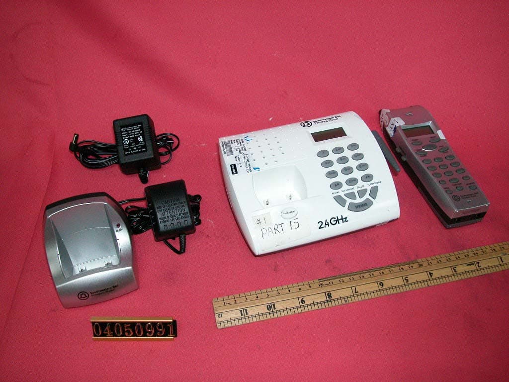
LBBGH3128AT
Jul 25, 20042.4GHz 40 Channel Cordless Phone w/ CID
Equipment Class
DXT - Part 15 Low Power Transceiver, Rx Verified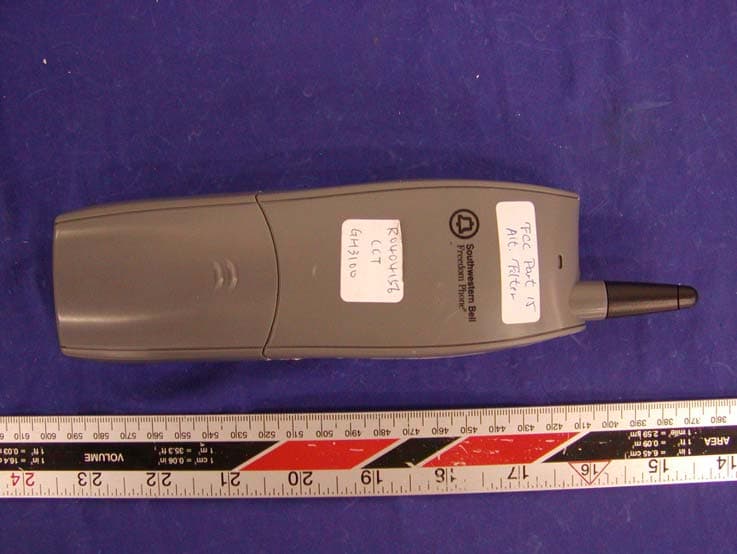
LBBGH3100H
May 06, 2004Cordless Phone
Equipment Class
DXX - Part 15 Low Power Communication Device Transmitter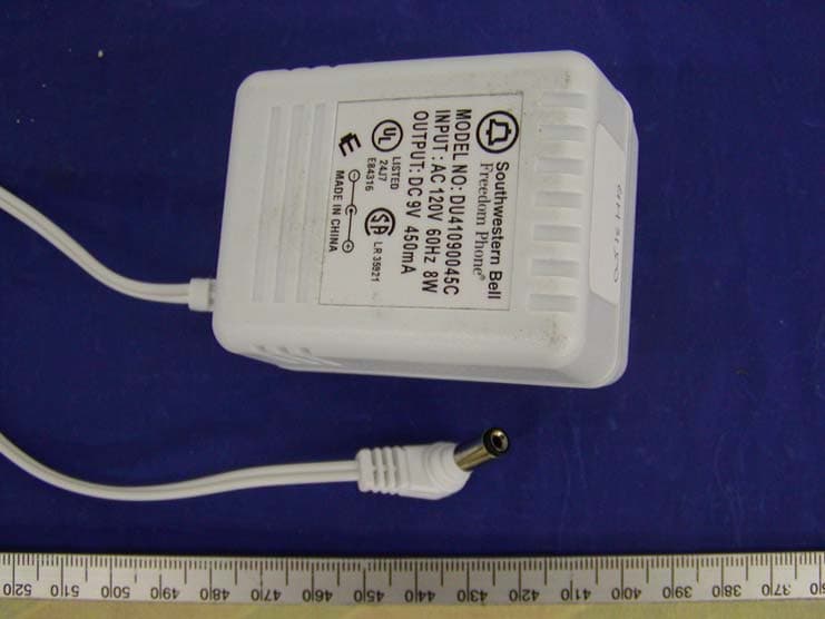
LBBGH3100
May 06, 2004Cordless Phone
Equipment Class
DXX - Part 15 Low Power Communication Device Transmitter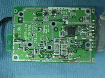
LBBGH3062
Apr 25, 20042.4 GHz Cordless Phone with Radio
Equipment Class
DXX - Part 15 Low Power Communication Device Transmitter
LBBGH4100
Apr 05, 20042.4GHz FHSS Cordless Phone w/ CID
Equipment Class
DSS - Part 15 Spread Spectrum Transmitter