LBBHUM1200GMRS Radio
Continental Conair Limited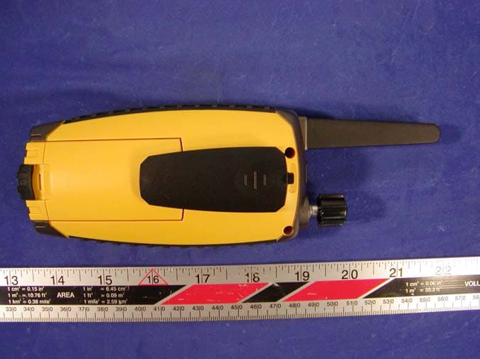
Click to zoom
Application Details
- Equipment Class
- FRF - Part 95 Family Radio Face Held Transmitter
- Date of Grant
- Feb 21, 2004
- Application Purpose
- Original Equipment
- Date of Application
- Feb 21, 2004
- Equipment Note
- GMRS Radio
- Frequency Range
- 462.55000000 - 467.72000000
- Company
- Continental Conair Limited
- Country
- Hong Kong
Documents & Files
Document Text
Text extracted from the exhibit documents filed with the FCC. Open a document above to read the original.
Users Manual
22 Channel With CTCSS GMRS Radio with 10 NOAA Weather Channels Model # HUM1200 Before operating your HUM1200, please read this instruction manual completely. HUM1200 2/11/04 8:27 PM Page 1 HUM1200 2/11/04 8:27 PM Page 2 CAUTIONS GMRS LICENSE USE OF THIS RADIO WITHIN THE UNITED STATES REQUIRES AN FCC GMRS LICENSE. AN INDIVIDUAL 18 YEARS OF AGE OR OLDER, WHO IS NOT A REPRESENTATIVE OF A FOREIGN GOVERNMENT IS ELIGIBLE TO APPLY FOR A GMRS SYSTEM LICENSE. YOU WILL NEED TWO FORMS FROM THE FCC: FCC FORM 159 AND FCC FORM 605 MAIN FORM AND SCHEDULE F. YOU CAN FIND THE FORMS ONLINE AT HTTP://WWW.FCC.GOV/FORMPAGE.HTML, OR CALL 1-800-418-3676. zNEVER HOLD THE TRANSCEIVER SO THAT THE ANTENNA IS VERY CLOSE TO, OR TOUCHING EXPOSED PARTS OF THE BODY WHILE TRANSMITTING. THE TRANSCEIVER WILL PERFORM BEST IF THE MICRO PHONE IS 2.5-5CM (1 to 2 INCHES) AWAY FROM THE MOUTH AND THE TRANSCEIVER IS VERTICAL. zThis handheld radio has been tested and meets the FCC RF exposure guidelines when used with the TTI or authorized OEM dealer’s accessories supplied or designated for this product. Use of other accessories may not comply with FCC RF exposure guideline. zDO NOT push the PTT button when not actually trying to transmit. WARNING: Changes and Modifications not expressly approved by Conair Consumer Electronics could void user’s authority to operate the equipment. NOTE:Please keep all packaging material for at least 90 days, in case you need to return this product to your place of purchase or to Conair Corporation. If metal from antenna becomes exposed, do not use unit. Contact with exposed metal antenna can cause burns. 3 HUM1200 2/11/04 8:27 PM Page 3 Safety Training Information Your radio generates RF electromagnetic energy during transmit mode. This radio is designed for and classified as “Occupational Use Only”, meaning it must be used only during the course of employment by indi- viduals aware of the hazards, and ways to minimize such hazards. This radio is NOT intended for use by the “General Population” in an uncontrolled environment. This radio has been tested and complies with the FCC RF exposure limits for “Occupational Use Only”. In addition, the radio complies with the following Standards and Guidelines with regard to RF energy and electromagnetic energy levels and evaluation of such levels for exposure to humans: zFCC OET Bulletin 65 Edition 97-01 Supplement C, Evaluating Compliance with FCC Guidelines for Human Exposure to Radio Frequency Electromagnetic Fields. zAmerican National Standards Institute (C95.1-1992), IEEE Standard for Safety Levels with Respect to Human Exposure to Radio Frequency Electromagnetic Fields, 3KHz to 300 GHz. zAmerican National Standards Institute (C95.3-1992), IEEE Recommended Practice for the Measurement of Potentially Hazardous Electromagnetic Fields-RF and Microwave. zTo ensure that your exposure to RF electromagnetic energy is within the FCC allowable limits for occupational use, always adhere to the following guidelines: zDO NOT operate the radio without a proper antenna attached, as this may damage the radio and may also cause you to exceed FCC RF exposure limits. A proper antenna is the antenna supplied with this radio by the manufacturer or an antenna specifically authorized by the manufacturer for use with this radio. zDO NOT transmit for more than 50% of total radio use time (“50% duty cycle”). Transmitting more than 50% of the time can cause FCC RF exposure compliance requirements to be exceeded. The radio is transmitting when the “TX indicator” lights red. You can cause the radio to transmit by pressing “PTT” switch. zALWAYS use authorized accessories (antennas, batteries, belt clips, speaker/mic, etc). Use of unauthorized accessories can 4 HUM1200 2/11/04 8:27 PM Page 4 cause FCC RF exposure compliance requirements to be exceeded. zALWAYS keep the antenna at least 2.5cm (1inch) away from the body when transmitting, and only use the belt-clips when attaching the radio to your belt, etc., to ensure FCC RF exposure compliance requirements are not exceeded. To provide the recipients of your transmission the best sound quality, hold the antenna at least 5cm (2 inches) from mouth, slightly away from mouth, and slightly off to one side. zThe information listed above provides the user with the information needed to make him or her aware of RF exposure, and what to do to assure that this radio operates within the FCC RF exposure limits. Electromagnetic Interference/Compatibility During transmissions, your radio generates RF energy that can possibly cause interference with other devices or systems. To avoid such interfer- ence, turn off the radio in areas where signs are posted to do so. DO NOT operate the transmitter in areas that are sensitive to electromagnetic radia- tion, such as hospitals, aircraft, and blasting sites. 5 HUM1200 2/11/04 8:27 PM Page 5 Contents FCC NOTICE............................................................................................ 8 FEATURES ............................................................................................... 9 CONTROLS AND INDICATORS...........................................................11 LCD Display Indicators ...........................................................................13 OPERATION ............................................................................................14 Turning On Your Unit ..............................................................................15 Adjusting The Volume..............................................................................15 Talking To Another Party .........................................................................15 Compass Button .......................................................................................16 Menu Button.............................................................................................17 Selecting Main Channels (1-22)...............................................................18 Selecting T…
Text truncated - open the document above for the full version.
External Photos
APPENDIX C - EUT EXTERNAL PHOTOGRAPHS Chassis - Front View Chassis – Rear View EUT – Top View
ID Label/Location Info
APPENDIX A - FCC ID LABELING AND LOCATION Proposed FCC ID Labeling Proposed FCC ID Location Rear Side of EUT / Proposed Label Location Labeling Requirement Each equipment for which a type acceptance applications is filed on or after May 1, 1981, shall bear an identification plate or label pursuant to §2.295 (Identification of Equipment) and §2.926 (FCC identifier) In August 1996 the Federal Communications Commissions (FCC) adopted RF exposure guidelines with safety levels for hand-held wireless devices. Generally users manual contains a RF exposure statement to indicate compliance with FCC requirements. The users manual should also contain required information and instruction pursuant to 95.653. FCC ID: LBBHUM1200 FCC ID: LBBHUM1200
Internal Photos
APPENDIX C - EUT INTERNAL PHOTOGRAPHS EUT – Housing and Board View EUT - Component View EUT – Component View with Shielding Removed EUT – Solder View EUT – Antenna Connection View
Parts List/Tune Up Info
Test and Alignment Procedure HUM1200CS/HUM1250CS 1. Recommended Test Equipment 1.1 HP8920A Communication Test Set 1.2 Fluke 50S Digital Thermometer 1.3 Fluke 77 Digital Voltmeter 1.4 Power Supply 2. Test Preparation 2.1 Connect a 6.0Vdc power source to the positive terminal input point and the negative battery input point (GND) for negative terminal. 2.2 Connect a communication test set capable of at least five watts RF to antenna test point. 2.3 Connect a 1 watt 16ohm resistor from speaker +SP to -SP. 2.4 Test point +SP should be connected to Audio In HI of the HP8920A. 2.5 Test point -SP should be connected to Audio In LO of the HP8920A. 3. Voltage Regulator Test 3.1 Connect a voltmeter to output of regulator TP29 (Bvout) and measure the voltage. The DC value must be between 3.725 and 3.875Vdc. 4. Temperature Compensation Alignment 4.1 Connect a voltmeter to TP19 (TEMP_DET). 4.2 Record the current ambient temperature (TA). 4.3 From the temperature compensation alignment table, determine the target voltage (Vtemp) based on the ambient temperature (TA). 4.4 Adjust VR1 until the voltmeter reading equal to the target voltage (Vtemp). Temperature Compensation Alignment Table Voltage A.Temp low nominal high 15°C 1.130 1.150 1.172 16°C 1.089 1.108 1.130 17°C 1.050 1.069 1.089 18°C 1.011 1.030 1.050 19°C 0.974 0.992 1.011 20°C 0.937 0.955 0.974 21°C 0.903 0.920 0.937 22°C 0.869 0.885 0.903 23°C 0.836 0.852 0.869 24°C 0.804 0.820 0.836 25°C 0.774 0.789 0.804 26°C 0.745 0.759 0.774 27°C 0.716 0.730 0.745 28°C 0.689 0.702 0.716 29°C 0.662 0.675 0.689 30°C 0.636 0.649 0.662 31°C 0.612 0.623 0.636 32°C 0.588 0.599 0.612 33°C 0.566 0.576 0.588 34°C 0.545 0.555 0.566 35°C 0.522 0.533 0.545 5. Battery Detect Alignment 5.1 Connect a voltmeter to TP20 (BATT_DET). 5.2 Adjust power supply to 4.80Vdc +/- 10mV. 5.3 Select one resistor from R208 to R210 until the voltmeter reading is close to 1.60Vdc +/- 40mV. 6. Battery Level Test 6.1 Adjust power supply to 5.5Vdc +/- 50mV. 6.2 Cycle power by turning the unit Off then On. 6.3 Check 3 segments of the battery level icons are solid. 6.4 Adjust power supply to 4.7Vdc +/- 50mV. 6.5 Cycle power by tuning the unit Off then On. 6.6 Check 2 segments of the battery level icons are solid. 6.7 Adjust power supply to 4.4Vdc +/- 50mV. 6.8 Cycle power by tuning the unit Off then On. 6.9 Check 1 segments of the battery level icons are solid. 6.10 Adjust power supply to 4.1Vdc +/- 50mV. 6.11 Cycle power by tuning the unit Off then On. 6.12 Check only shell of the battery level icons are solid. 6.13 Readjust power supply to 6.0Vdc. 7. Crystal Select 7.1 Crystal X1 are marked with red, blue, green or orange colour marks. 7.2 All crystal select resistors R202 to R205 are installed during SMT. During PCBA alignement, two of resistors must be removed depending on the crystal colour marking as shown in the crystal selection table. Crystal Selection Table Rank Colour R202 R203 R204 R205 A Red DNI Insert DNI Insert B Blue DNI Insert Insert DNI C Green Insert DNI DNI Insert D Orange Insert DNI Insert DNI 8. VCO Alignment 8.1 Set unit to Channel 1 and connect a voltmeter to TP9. 8.2 Press the PTT switch so unit is in transmit mode. 8.3 Adjust VC1 until the voltmeter read 0.6Vdc +/- 0.1V. VC1 is located under the VCO shield can and is accessible through the hole cut-out. 8.4 Release the PTT switch and observe the voltage on TP9. The voltage should be in the range of 0.5 to 1.0Vdc. 8.5 Set unit to channel 14 and connect a voltmeter to TP9. 8.6 Press the PTT switch and observe the voltage on TP9. The voltage should be between 0.8 to 1.6Vdc. 8.7 Release PTT and observe the voltage on TP9. The voltage should be between 1.0 to 1.8Vdc. 9. Transmitter Frequency Alignment 9.1 Press the PTT switch so unit is in transmit mode. 9.2 Adjust VC2 such that the output frequency is equal to the channel frequency with a maximum error +/-200Hz. VC2 is located near the crystal unit of X1. 10. Transmitter Output Power Check 10.1 Set unit to channel 1 (Low Power Mode). 10.2 Press the PTT switch so unit is in transmit mode. 10.3 Transmit power should be between 400mW to 500mW. 10.4 Set unit to High Power Mode. 10.5 Press the PTT switch so unit is in transmit mode. 10.6 Transmit power should be 2W +/- 0.3W. 10.7 Set unit to channel 14. 10.8 Press the PTT switch so unit is in transmit mode. 10.9 Transmit power should be between 400mW to 500mW. Note: The power can be adjusted from low to high or vice versa when at GMRS channel (1~7, 15~22). The FRS channel(8~14) is fixed at low power. 11. Transmitter Deviation Adjustment 11.1 Connect an audio generator (600ohm) to the microphone test points MIC+ and GND. The audio frequency should be set a 1kHz with a level of 50mV RMS. 11.2 Connect an FM deviation meter (communication test set) to antenna test point. Set the deviation meter to read peak to peak maximum deviation. Set Filter 1 to 50Hz HPF. Set Filter 2 to 15kHz LPF. 11.3 Set unit to channel 1 with CTCSS code 1. Press the PTT switch so unit is in transmit mode. 11.4 Adjust VR2 for 2.15kHz deviation (+/-0.05kHz). 11.5 Set unit to channel 1 with CTCSS code 38. Check deviation should be less than 2.5kHz. 11.6 Repeat step 11.5 for channel 14 with CTCSS code 1. 11.7 Repeat step 11.5 for channel 14 with CTCSS code 38. 11.8 Set unit to channel 1 with CTCSS code 0. 11.9 Decrease audio generator level until deviation reads +/- 1.5kHz and record generator level. Level should be between 5mV and 15mV. 11.10 Set Filter 1 to 300Hz HPF. Set Filter 2 to 3kHz LPF. Make sure to turn on de- emphasis. 11.11 Check that transmit audio distortion is less than 5%. 11.12 Switch off the audio generator. 11.13 Set Filter 1 to 50Hz HPF. Set Filter 2 to 300Hz LPF. 11.14 Set unit to channel 1 with CTCSS code 1. 11.15 Check that the CTCSS code deviation is in the range between +/- 250 to 500Hz. 11.16 Repeat step 11.15 for channel 1 with CTCSS code 38. 11.17 Repeat step 11.15 for channel 14 with CTCSS code 1. 11.18 Repeat step 11.15 for chann…
Text truncated - open the document above for the full version.
RF Exposure Info
Note: This test report is specially limited to the above client company and the product model only. It may not be duplicated without prior written consent of Bay Area Compliance Laboratory Corporation. This report must not be used by the client to claim product endorsement by NVLAP or any agency of the U.S. Government. SAR EVALUATION REPORT For Continental Conair Limited 35/F Standard Chartered Tower Millennium City, 388 Kwun Tong Road Kwun Tong, Kowloon, HK FCC ID: LBBHUM1200 2004-02-02 This Report Concerns: Original Report Equipment Type: GMRS Radio Test Engineer: Eric Hong / Report No.: R0401124S Test Date: 2004-01-013 Reviewed By: Ling Zhang / Prepared By: Bay Area Compliance Laboratory Corporation 230 Commercial Street Sunnyvale, CA 94085 Tel: (408) 732-9162 Fax: (408) 732 9164 Continental Conair Limited FCC ID: LBBHUM1200 Report #R0401124S SAR Evaluation Report Page 2 of 41 TABLE OF CONTENTS SUMMARY....................................................................................................................................................................3 1 - REFERENCE ...........................................................................................................................................................4 2 - TESTING EQUIPMENT.........................................................................................................................................5 2.2 EQUIPMENT CALIBRATION CERTIFICATE...............................................................................................................5 3 - EUT DESCRIPTION .............................................................................................................................................17 4 - SYSTEM TEST CONFIGURATION...................................................................................................................18 4.1 JUSTIFICATION.....................................................................................................................................................18 4.2 EUT EXERCISE PROCEDURE................................................................................................................................18 4.3 EQUIPMENT MODIFICATIONS...............................................................................................................................18 5 – CONDUCTED OUTPUT POWER ......................................................................................................................19 5.1 PROVISION APPLICABLE.......................................................................................................................................19 5.2 TEST PROCEDURE................................................................................................................................................19 5.3 TEST EQUIPMENT.................................................................................................................................................19 5.4 TEST RESULTS.....................................................................................................................................................19 6 - DOSIMETRIC ASSESSMENT SETUP...............................................................................................................20 6.1 MEASUREMENT SYSTEM DIAGRAM.....................................................................................................................21 6.2 SYSTEM COMPONENTS.........................................................................................................................................22 6.3 MEASUREMENT UNCERTAINTY............................................................................................................................26 7 - SYSTEM EVALUATION .....................................................................................................................................27 7.1 SIMULATED TISSUE LIQUID PARAMETER CONFIRMATION...................................................................................27 7.2 EVALUATION PROCEDURES..................................................................................................................................27 7.3 SYSTEM ACCURACY VERIFICATION.....................................................................................................................28 7.4 SAR EVALUATION PROCEDURE...........................................................................................................................31 7.5 EXPOSURE LIMITS................................................................................................................................................32 8 - TEST RESULTS ....................................................................................................................................................33 8.1 SAR TEST DATA..................................................................................................................................................33 8.2 PLOTS OF TEST RESULT.......................................................................................................................................33 EXHIBIT A - SAR SETUP PHOTOGRAPHS .........................................................................................................36 BODY-WORN WITH BELT CLIP & HEADSET IN TOUCHING WITH PHANTOM...............................................................36 2.5CM SEPARATION TO FLAT PHANTOM.....................................................................................................................36 EXHIBIT B - EUT PHOTOGRAPHS .......................................................................................................................37 CHASSIS - FRONT VIEW.............................................................................................................................................37 CHASSIS – REAR VIEW..................................................…
Text truncated - open the document above for the full version.
Test Report
Note: This test report is specially limited to the above client company and product model. It may not be duplicated without prior written consent of Bay Area Compliance Laboratory Corporation. This report must not be used by the client to claim product endorsement by NVLAP or any agency of the U.S. Government. FCC PART 95 EMI MEASUREMENT AND TEST REPORT For Continental Conair Limited 35/F Standard Chartered Tower Millennium City, 388 Kwun Tong Road Kwun Tong, Kowloon, HK FCC ID: LBBHUM1200 2004-02-02 This Report Concerns: Original Report Equipment Type: GMRS Radio Test Engineer: Ming Jing / Report Number: R0401124 Test Date: 2004-01-19 Reviewed By: Ling Zhang / Prepared By: Bay Area Compliance Laboratory Corporation 230 Commercial Street Sunnyvale, CA 94085 Tel: (408) 732-9162 Fax: (408) 732 9164 Continental Conair Limited FCC ID: LBBHUM1200 Report # R0401124Rpt FCC Part 95 Test Report Page 2 of 23 TABLE OF CONTENTS GENERAL INFORMATION.......................................................................................................................................4 PRODUCT DESCRIPTION FOR EQUIPMENT UNDER TEST (EUT) ....................................................................................4 OBJECTIVE...................................................................................................................................................................4 RELATED GRANT/SUBMISSION.....................................................................................................................................4 TEST METHODOLOGY..................................................................................................................................................4 TEST FACILITY.............................................................................................................................................................5 EXTERNAL I/O CABLING LIST AND DETAILS...............................................................................................................5 SYSTEM TEST CONFIGURATION ..........................................................................................................................6 JUSTIFICATION.............................................................................................................................................................6 EUT TEST CONFIGURATION........................................................................................................................................6 SPECIAL ACCESSORIES.................................................................................................................................................6 SCHEMATICS / BLOCK DIAGRAM.................................................................................................................................6 EQUIPMENT MODIFICATIONS.......................................................................................................................................6 CONFIGURATION OF TEST SYSTEM..............................................................................................................................6 TEST SETUP BLOCK DIAGRAM.....................................................................................................................................7 REQUIREMENTS OF PROVISIONS ........................................................................................................................8 §2.1046, §95.639(D), AND §95.639 (A)(1) - EFFECTIVE RADIATED POWER ....................................................9 STANDARD APPLICABLE..............................................................................................................................................9 TEST PROCEDURE........................................................................................................................................................9 TEST EQUIPMENT.......................................................................................................................................................10 ENVIRONMENTAL CONDITIONS..................................................................................................................................10 TEST RESULTS...........................................................................................................................................................10 §2.1047, §95.631(D), §95.637(A), AND § 95.637(B) - MODULATION CHARACTERISTICS ...........................12 STANDARD APPLICABLE............................................................................................................................................12 TEST PROCEDURE......................................................................................................................................................12 TEST EQUIPMENT.......................................................................................................................................................12 ENVIRONMENTAL CONDITIONS..................................................................................................................................13 TEST RESULTS...........................................................................................................................................................13 §2.1049, §95.633(A), AND § 95.633(C) - OCCUPIED BANDWIDTH OF EMISSION.........................................15 STANDARD APPLICABLE............................................................................................................................................15 TEST PROCEDURE......................................................................................................................................................15 TEST EQUIPMENT.......................................................................................................................................................15 ENVIRONMENTAL CONDITIONS................…
Text truncated - open the document above for the full version.
Test Setup Photos
APPENDIX B - TEST SETUP PHOTOGRAPHS Radiated Emission - Front View Radiated Emission - Rear View
Contact Information
Applicant
David Ng(Manager, Consumer Electronics)
852 2751 4688Fax: 852 2751 8920
Test Firm
Bay Area Compliance LaboratoryJohn Chan
Technical Specifications
| # | Rule Parts | Frequency Range | Power Output | Emission | Tolerance |
|---|---|---|---|---|---|
| 2 | 95A | 462.55 MHz - 467.72 MHz | 1.82 W | 11K0F3E | 2.5 ppm |
Other Applications from Continental Conair Limited
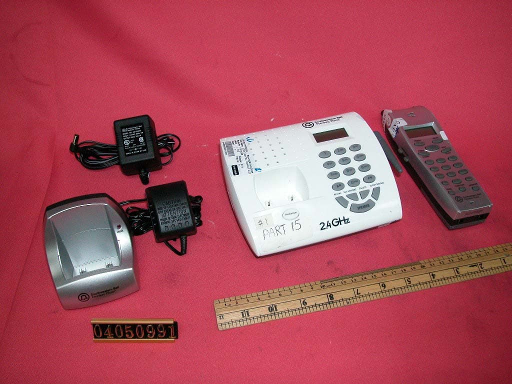
LBBGH3128AT
Jul 25, 20042.4GHz 40 Channel Cordless Phone w/ CID
Equipment Class
DXT - Part 15 Low Power Transceiver, Rx Verified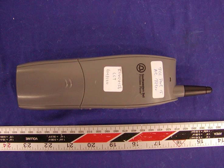
LBBGH3100H
May 06, 2004Cordless Phone
Equipment Class
DXX - Part 15 Low Power Communication Device Transmitter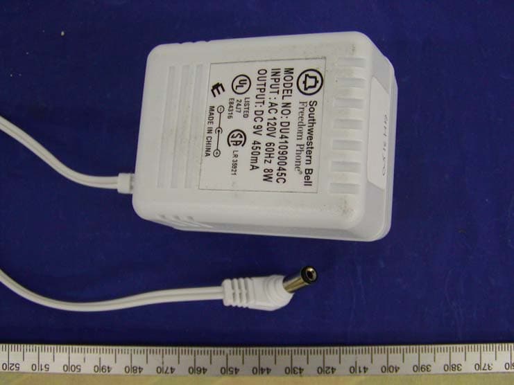
LBBGH3100
May 06, 2004Cordless Phone
Equipment Class
DXX - Part 15 Low Power Communication Device Transmitter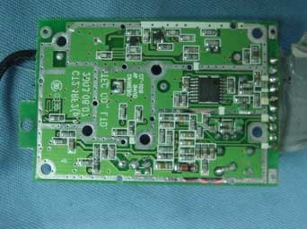
LBBGH3062
Apr 25, 20042.4 GHz Cordless Phone with Radio
Equipment Class
DXX - Part 15 Low Power Communication Device Transmitter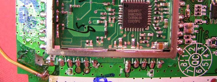
LBBGH4100
Apr 05, 20042.4GHz FHSS Cordless Phone w/ CID
Equipment Class
DSS - Part 15 Spread Spectrum Transmitter