LC3810R901G01Personal Communication Unit - PCU
Northrop Grumman Corporation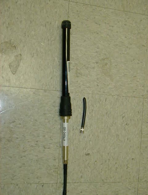
Click to zoom
Application Details
- Equipment Class
- DTS - Digital Transmission System
- Date of Grant
- Apr 15, 2003
- Application Purpose
- Original Equipment
- Date of Application
- Apr 15, 2003
- Equipment Note
- Personal Communication Unit - PCU
- Frequency Range
- 2402.00000000 - 2480.00000000
- Company
- Northrop Grumman Corporation
- Country
- United States
Documents & Files
Document Text
Text extracted from the exhibit documents filed with the FCC. Open a document above to read the original.
Users Manual
M M o o u u n n t t e e d d W W a a r r r r i i o o r r S S o o l l d d i i e e r r S S y y s s t t e e m m C C o o r r d d l l e e s s s s C C o o m m m m u u n n i i c c a a t t i i o o n n s s C C o o r r d d l l e e s s s s C C o o m m m m u u n n i i c c a a t t i i o o n n s s S S y y s s t t e e m m ( ( C C C C S S ) ) U U S S E E R R O O V V E E R R V V I I E E W W M M o o u u n n t t e e d d W W a a r r r r i i o o r r C C o o r r d d l l e e s s s s C C o o m m m m u u n n i i c c a a t t i i o o n n s s S S y y s s t t e e m m ( ( C C C C S S ) ) • Add-on to existing VIS (Vehicle Intercom Set) • User stays connected to Intercom/Radio without being physically connected to vehicle by wire or cable • Retains all features of existing VIS equipment • User may move about vehicle un-tethered • User may completely dismount vehicle • Dismounted user can talk over Intercom/Radio up to 250 meters away from vehicle. • Two-way radio feature for multiple dismounted users. U U n n i i v v e e r r s s a a l l A A d d a a p p t t e e r r I I n n t t e e r r f f a a c c e e ( ( U U A A I I ) ) M M o o u u n n t t i i n n g g B B r r a a c c k k e e t t s s I I n n t t e e r r i i o o r r A A n n t t e e n n n n a a C C o o n n n n e e c c t t o o r r E E x x t t e e r r i i o o r r A A n n t t e e n n n n a a C C o o n n n n e e c c t t o o r r C C a a b b l l e e C C o o n n n n e e c c t t o o r r t t o o F F F F C C S S C C a a b b l l e e C C o o n n n n e e c c t t o o r r t t o o F F F F C C S S B B a a i i l l o o u u t t C C a a b b l l e e C C o o n n n n e e c c t t o o r r t t o o P P C C U U I I n n t t e e r r f f a a c c e e C C a a b b l l e e C C o o n n n n e e c c t t o o r r t t o o R R D D U U R R e e m m o o t t e e D D i i s s p p l l a a y y U U n n i i t t ( ( R R D D U U ) ) Display Keypad Mounting Brackets Interface Cable Connector (to UAI) P P e e r r s s o o n n a a l l C C o o m m m m u u n n i i c c a a t t i i o o n n s s U U n n i i t t ( ( P P C C U U ) ) Fully Assembled Disassembled Bailout connection to UAI Antenna connector Data connector Keypad Belt Clip Battery Pack Bailout connection to Headset Battery Release LED Display C C C C S S W W i i r r i i n n g g D D i i a a g g r r a a m m * * * for reference on ly / conn ec tor loca tion s a pp roximate UAI RDU PCU HEADSE T Bailout Connection – detach for remote u se FF CS PCU HEADSE T Bailout Connection – detach for remote u se GUNNER COMM ANDER / DRIVE R / SOLDIER FF CS R R D D U U K K e e y y p p a a d d & & D D i i s s p p l l a a y y P P P O O O W W W E E E R R R O O O N N N / / / O O O F F F F F F M M M O O O D D D E E E S S S E E E L L L E E E C C C T T T I I I N N N C C C R R R E E E M M M E E E N N N T T T D D D E E E C C C R R R E E E M M M E E E N N N T T T L L L E E E D D D D D D I I I S S S P P P L L L A A A Y Y Y RDU Display automatically goes blank after 5 seconds if no buttons are pressed. Press MODE SELECT button to restore display. R R D D U U M M O O D D E E S S P r ess t o s cr ol l through modes . 1 . B I T (Built-In T es t) Runs self-test and displays result. Will see ; press OR to run self- test. Automatically displays if passed, OR THRU if failed. NOTE: When powering-on, RDU automatically runs BIT & displays result. 2 . CH ANNE L Displays current channel: THRU . Press OR to change channel. 3 . VOL U ME Displays current volume: (softest) THRU (loudest). Press OR to increase/decrease volume. 4 . OPE R AT I NG MODE Displays current UAI operating mode: (Local) * OR (Broadcast) OR (Group) OR (Listening Silence). Press OR to change operating mode. * Default at power-up is Local mode 5 . AU DI O/DAT A Displays current setting: (audio) OR (data). Press OR to toggle setting. P P C C U U D D i i s s p p l l a a y y * * P P C C U U A A n n t t e e n n n n a a Display automatically goes blank after 5 seconds if no buttons are pressed. Press MODE SELECT button to restore display. C C C O O O N N N N N N E E E C C C T T T O O O R R R ( ( ( B B B N N N C C C T T T y y y p p p e e e ) ) ) To remove, twist connector counter- clockwise and pull off. To attach, push in and twist connector clockwise until locked. *Display shuts off when PCU is connected to bailout cable P P C C U U K K e e y y p p a a d d M M M O O O D D D E E E S S S E E E L L L E E E C C C T T T P P P O O O W W W E E E R R R O O O N N N / / / O O O F F F F F F D D D E E E C C C R R R E E E M M M E E E N N N T T T I I I N N N C C C R R R E E E M M M E E E N N N T T T NOTE: PCU Display automatically goes blank after 5 seconds if no buttons are pressed. Press MODE SELECT button to restore display. P P C C U U M M O O D D E E S S P r ess t o s cr ol l through modes . 1 . B I T (Built-In T es t) Runs self-test and displays result. Will see ; press OR to run self- test. Automatically displays if passed, OR THRU if failed. NOTE: When powering-on, PCU automatically runs BIT & displays result. 2 . CH ANNE L Displays current channel: THRU . Press OR to change channel. 3 . VOL U ME Displays current volume: (softest) THRU (loudest). Press OR to increase/decrease volume. 4 . AU DI O/DAT A Displays current setting: (audio) OR (data). Press OR to toggle setting. 5 . B ATTERY ST AT US Displays current battery charge level: (>10% charge remaining) THRU (>90% charge remaining). NOTE: If b0 is seen, battery has less than 10% charge remaining and PCU will automatically shut off after 1 minute of further use. If b_ or blinking F1 is seen, PCU is still attempting to sense charge level; may take up to 3 minutes when PCU is first powered-on. P P C C U U B B a a t t t t e e r r y y P P a a c c k k L L O O C C K K T T A A B B S S R R E E L L E E A A S S E E L L A A T T C C H H S S O O C C K K E E T T S S C C O O N N T T A A C C T T S S • F ully-charged bat t er y provides at leas t 4 hrs of remote us e • B attery does not us e char ge w hi l e P CU is connected t o cr ew s t at i on • Audi bl e al ar m is heard i n heads et when char ge dr ops below 20% ! AVOI D …
Text truncated - open the document above for the full version.
Users Manual
S S a a f f e e t t y y / / U U s s a a g g e e C C o o n n s s i i d d e e r r a a t t i i o o n n s s • • E E n n s s u u r r e e a a l l l l c c o o n n n n e e c c t t i i o o n n s s a a r r e e s s e e c c u u r r e e p p r r i i o o r r t t o o u u s s e e • • K K e e e e p p P P C C U U & & U U A A I I a a n n t t e e n n n n a a a a t t l l e e a a s s t t 2 2 0 0 c c m m ( ( 8 8 i i n n c c h h e e s s ) ) a a w w a a y y f f r r o o m m i i n n d d i i v v i i d d u u a a l l s s w w / / p p a a c c e e m m a a k k e e r r • • K K e e e e p p P P C C U U / / U U A A I I v v o o l l u u m m e e a a t t m m i i n n i i m m u u m m f f u u l l l l y y - - a a u u d d i i b b l l e e l l e e v v e e l l • • D D o o n n o o t t s s h h o o r r t t c c o o n n t t a a c c t t s s o o n n b b a a t t t t e e r r y y p p a a c c k k ; ; k k e e e e p p l l o o o o s s e e b b a a t t t t e e r r i i e e s s a a w w a a y y f f r r o o m m m m e e t t a a l l o o b b j j e e c c t t s s • C C e e a a s s e e u u s s e e o o f f C C C C S S i i m m m m e e d d i i a a t t e e l l y y u u p p o o n n e e r r r r a a t t i i c c o o r r u u n n e e x x p p e e c c t t e e d d v v e e h h i i c c l l e e b b e e h h a a v v i i o o r r . . ! S S a a f f e e t t y y / / U U s s a a g g e e C C o o n n s s i i d d e e r r a a t t i i o o n n s s (CONTINUED) • • A A l l l l c c r r i i t t i i c c a a l l v v o o i i c c e e c c o o m m m m u u n n i i c c a a t t i i o o n n s s h h o o u u l l d d b b e e r r e e p p e e a a t t e e d d b b a a c c k k t t o o o o r r i i g g i i n n a a t t o o r r • • C C h h a a n n g g e e s s o o f f s s e e t t t t i i n n g g / / m m o o d d e e m m a a y y r r e e s s u u l l t t i i n n b b r r i i e e f f l l o o s s s s o o f f c c o o m m m m u u n n i i c c a a t t i i o o n n ( ( 2 2 - - 4 4 s s e e c c ) ) - - - - a a l l l l o o w w P P C C U U d d i i s s p p l l a a y y t t o o b b l l a a n n k k b b e e f f o o r r e e t t r r a a n n s s m m i i t t t t i i n n g g • • R R e e m m o o v v i i n n g g b b a a i i l l o o u u t t c c a a b b l l e e f f o o r r r r e e m m o o t t e e u u s s e e m m a a y y r r e e s s u u l l t t i i n n 6 6 - - 8 8 s s e e c c l l o o s s s s o o f f c c o o m m m m . . • • C C C C S S V V O O X X i i s s l l e e s s s s s s e e n n s s i i t t i i v v e e t t h h a a n n w w i i r r e e d d V V I I C C - - 3 3 V V O O X X ; ; m m a a y y r r e e q q u u i i r r e e l l o o u u d d e e r r v v o o i i c c e e / / i i n n f f l l e e c c t t i i o o n n t t o o a a c c t t i i v v a a t t e e • • M M i i c c b b o o o o m m s s h h o o u u l l d d b b e e t t o o u u c c h h i i n n g g l l i i p p s s w w h h e e n n t t a a l l k k i i n n g g t t o o e e n n s s u u r r e e V V O O X X i i s s m m a a i i n n t t a a i i n n e e d d . . ! S S a a f f e e t t y y / / U U s s a a g g e e C C o o n n s s i i d d e e r r a a t t i i o o n n s s (CONTINUED) • • R R e e m m o o t t e e p p e e r r s s o o n n n n e e l l w w i i l l l l n n o o t t i i c c e e s s t t a a t t i i c c / / d d e e c c r r e e a a s s e e i i n n s s i i g g n n a a l l q q u u a a l l i i t t y y w w h h e e n n m m o o v v i i n n g g o o u u t t o o f f r r a a n n g g e e o o f f v v e e h h i i c c l l e e ( ( > > 2 2 5 5 0 0 m m ) ) . . • • I I f f c c o o m m m m . . i i s s l l o o s s t t d d u u e e t t o o m m o o v v i i n n g g o o u u t t o o f f r r a a n n g g e e , , u u s s e e r r m m a a y y h h a a v v e e t t o o m m o o v v e e c c o o m m p p l l e e t t e e l l y y b b a a c c k k w w i i t t h h i i n n r r a a n n g g e e o o f f v v e e h h i i c c l l e e t t o o r r e e c c o o v v e e r r c c o o m m m m . . • • W W h h e e n n o o p p e e r r a a t t i i n n g g r r e e m m o o t t e e l l y y , , l l o o s s s s o o f f P P C C U U P P o o w w e e r r w w i i l l l l r r e e s s u u l l t t i i n n l l o o s s s s o o f f H H e e a a d d s s e e t t f f u u n n c c t t i i o o n n s s ( ( A A N N R R a a n n d d a a u u d d i i o o p p a a s s s s - - t t h h r r o o u u g g h h ) ) • • P P C C U U p p o o w w e e r r m m u u s s t t b b e e r r e e c c y y c c l l e e d d i i f f h h e e a a d d s s e e t t b b e e c c o o m m e e s s d d i i s s c c o o n n n n e e c c t t e e d d f f r r o o m m P P C C U U • • U U A A I I p p o o w w e e r r m m u u s s t t b b e e r r e e c c y y c c l l e e d d i i s s t t u u r r r r e e t t p p o o w w e e r r i i s s r r e e s s e e t t • • M M a a x x i i m m u u m m s s i i m m u u l l t t a a n n e e o o u u s s r r e e m m o o t t e e t t a a l l k k e e r r s s = = 4 4 . . C C u u r r r r e e n n t t t t a a l l k k e e r r s s h h a a v v e e p p r r i i o o r r i i t t y y ! S S a a f f e e t t y y / / U U s s a a g g e e C C o o n n s s i i d d e e r r a a t t i i o o n n s s (CONTINUED) • • R R a a d d i i o o a a c c c c e e s s s s f f o o r r A A L L L L r r e e m m o o t t e e P P C C U U s s i i s s d d e e t t e e r r m m i i n n e e d d b b y y s s e e t t t t i i n n g g s s o o f f F F F F C C S S c c o o n n n n e e c c t t e e d d t t o o U U A A I I ( ( i i . . e e . . G G u u n n n n e e r r ’ ’ s s F F F F C C S S ) ) • • C C o o o o r r d d i i n n a a t t e e a a s s s s i i g g n n e e d d c c h h a a n n n n e e l l s s f f o o r r e e a a c c h h v v e e h h i i c c l l e e p p r r i i o o r r t t o o m m i i s s s s i i o o n n . . • • U U A A I I s s / / P P C C U U s s s s h h o o u u l l d d s s w w i i t t c c h h b b a a c c k k t t o o a a s s s s i i g g n n e e d d c c h h a a n n n n e e l l a a f f t t e e r r G G r r o o u u p p o o r r A A u u t t o o n n o o m m o o u u s s u u s s e e • • C C h h a a n n n n e e l l 6 6 4 4 i i s s r r e e s s e e r r v v e e d d f f o o r r t t e e s s t t u u s s e e • • W W h h e e n n p p o o w w e e r r i i n n g g - - o o n n u u n n i i t t , , s s e e l l f f t t e e …
Text truncated - open the document above for the full version.
ID Label/Location Info
FCC Label location on UAI FCC Label location on PCU FCC Label
ID Label/Location Info
FCC ID: LC3817R191G01 This device complies with Part 15 of the FCC Rules. Operation is subject to the following conditions: (1) this device may not cause harmful interference, and (2) this device must accept any interference that may cause undesired operation. FCC ID: LC3810R901G01 This device complies with Part 15 of the FCC Rules. Operation is subject to the following conditions: (1) this device may not cause harmful interference, and (2) this device must accept any interference that may cause undesired operation.
RF Exposure Info
SAR EVALUATION CERTIFICATE OF COMPLIANCE FCC ID: LC3817R191G01 APPLICANT: Northrop Grumman. EUT:FHSS Transceiver (Mounted Warrior Cordless Communication System –PCU ) Date of Receipt:Dec. 18, 2002 Device Category:Part 15 C RF exposure environment:Uncontrolled RF exposure category:Portable Power supply:Powered by Battery Antenna: External Fixed Bar Antenna Production/prototype:Identical Prototype Measured Standards:Oet 65 Suppliment C Modulation:FHSS Crest Factor:FHSS = 1 TX Range:2.4 – 2.48 GHz RX Range:2.4 – 2.48 GHz Used TX Channels:Low: ch. FHSSCenter: ch FHSSHigh: ch. FHSS Maximum RF Power Output:0.0186W Conducted, 0.033W EIRP Maximum SAR Measurement (Averaged over 1g): 0.156 W/kg Body Chris Harvey Director, EMC Laboratory APPLICANT NAME AND ADDRESS: DATE OF TEST: Dec. 27, 2002 Northrop Grumman TEST LOCATION: MET LABORATORIES INC. P.O. Box 392 M/S A320 914 West Patapsco Ave. Baltimore, MD 21203 Baltimore, Maryland 21230 This wireless portable device has been tested in accordance with the measurement procedures specified in FCC/OET Bulletin 65 Supplement C (2001) and IEEE Std. 1528-200X (July 2001), and has been shown to be capable of compliance for localized specific absorption rate (SAR) for uncontrolled environment/general population exposure limits specified in ANSI/IEEE Std. C95.1 - 1992. I attest to the accuracy of this data. All reported measurements were performed by me, or were made under my supervision, and are correct to the best of my knowledge and belief. I assume full responsibility for the completeness of these measurements and vouch for the qualifications of all persons taking them. I also certify that no party to this application has been denied the FCC benefits pursuant to Section 5.301 of the Anti-Drug Abuse Act of 1988, 21 U.S.C. 862. Northrop GrummanMounted warrior cordless communication system FCC ID: LC3817R191G01December 27, 2002 EMC13035-SARCopyright 2003, MET Laboratories, Inc.Page 2 of 39 December 27, 2002 Northrop Grumman P.O. Box 392 M/S A320 Baltimore, MD 21203 Reference:FHSS Transceiver (Mounted Warrior Cordless Communication System – PCU ) FCC ID: LC3817R191G01 Dear Mr. Mark Gravel: Enclosed is the EMC SAR Evaluation Report for the FHSS Transceiver (Mounted Warrior Cordless Communication System – PCU ) FCC ID: LC3817R191G01 was tested in accordance with the measurement procedures specified in FCC OET 65 Supplement C:01-01 and shown to be capable to be in compliance for localized specific absorption rate (SAR) for uncontrolled environment/general population exposure limits specified in FCC OET 65 Supplement C:01-01. Thank you for using the testing services of MET Laboratories. If you have any questions regarding these results or if MET can be of further assistance to you, please feel free to contact me. We appreciate your business and look forward to working with you again soon. Kindest Regards, MET LABORATORIES, INC. Marianne T. Bosley EMC Administrator Enclosures: DOCTEM-23 Jan 02 Certificates and reports shall not be reproduced except in full, without the written permission of MET Laboratories, Inc. The Nation’s First Licensed Nationally Recognized Testing Laboratory Northrop GrummanMounted warrior cordless communication system FCC ID: LC3817R191G01December 27, 2002 EMC13035-SARCopyright 2003, MET Laboratories, Inc.Page 3 of 39 Dosimetric Assessment Test Report for the Northrop Grumman FHSS Transceiver (Mounted Warrior Cordless Communication System –PCU) Tested and Evaluated In Accordance With FCC OET 65 Supplement C:01-01 MET REPORT: EMC13035-SAR April 16, 2003 PREPARED FOR: Northrop Grumman P.O. Box 392 M/S A320 Baltimore, MD 21203 PREPARED BY: MET Laboratories, Inc. 914 West Patapsco Avenue Baltimore, Maryland 21230-3432 Northrop GrummanMounted warrior cordless communication system FCC ID: LC3817R191G01December 27, 2002 EMC13035-SARCopyright 2003, MET Laboratories, Inc.Page 4 of 39 Dosimetric Assessment TEST REPORT for the FHSS Transceiver (Mounted Warrior Cordless Communication System –PCU) Tested and Evaluated In Accordance With FCC OET Supplement C: 01-01 Prepared for Northrop Grumman P.O. Box 392 M/S A320 Baltimore, MD 21203 Report Prepared By Marianne T. Bosley EMC ADMINISTRATOR Report Reviewed By Liming Xu TEST ENGINEER CHRISTOPHER R. HARVEY EMC LAB DIRECTOR Engineering Statement: The measurements shown in this report were made in accordance with the procedures specified in Supplement C to OET Bulletin 65 of the Federal Communications Commission (FCC) Guidelines [FCC 2001] for uncontrolled exposure. I assume full responsibility for the accuracy and completeness of these measurements, and for the qualifications of all persons taking them. It is further stated that upon the basis of the measurements made, the equipment evaluated is capable of compliance for localized specific absorption rate (SAR) for uncontrolled environment/general population exposure limits specified in ANSI/IEEE Std. C95.1-1992. Northrop GrummanMounted warrior cordless communication system FCC ID: LC3817R191G01December 27, 2002 EMC13035-SARCopyright 2003, MET Laboratories, Inc.Page 5 of 39 Quick Links • Summary of test Report • EUT Description • Test Conditions • Host Laptops Used • System Validation • SAR results summary • SAR Area Scans • Setup Pictures • Measurement System Northrop GrummanMounted warrior cordless communication system FCC ID: LC3817R191G01December 27, 2002 EMC13035-SARCopyright 2003, MET Laboratories, Inc.Page 6 of 39 OBJECTIVE The objective of the procedure was to perform a dosimetric assessment one of the TDMA cell phone. The measurements have been carried out with the dosimetric assessment system “SARA2", and were made according to the Supplement C to OET Bulletin 65 of the Federal Communications Commission (FCC) Guidelines [FCC 2001] for evaluating compliance of mobile and portable devices with FCC limits for human exposure in the general population to radio frequency emissions. INTRODUCTION In the United States, the most recent FCC RF exposure cr…
Text truncated - open the document above for the full version.
RF Exposure Info
MPE limit Calculation: (Met 13035) Equation from page 18 of OET 65, Edition 97-01 S = PG / 4* pi* R 2 = 0.0186 x 6 / 12.566 x 0.04 = 0.1116 w /0.5 m 2 = 0.223mw / cm 2 S = Power density P = Power input to antenna (0.0186 w ) G = antenaa gain ( 6 dBi ) R = distance to the center of radiation of the antenna (0.2m ) MPE limit for uncontrolled exposure 1 mw / cm 2 The EUT power density @ 20 cm = 0.223 mw / cm 2
RF Exposure Info
IMMERSIBLE SAR PROBE CALIBRATION REPORT Part Number: IXP – 050 S/N 0122 25 th October 2002 Indexsar Limited Oakfield House Cudworth Lane Newdigate Surrey RH5 5DR Tel: +44 (0) 1306 631 233 Fax: +44 (0) 1306 631 834 e-mail: [email protected] INTRODUCTION This Report presents measured calibration data for a particular Indexsar SAR probe (S/N 0122) and describes the procedures used for characterisation and calibration. Indexsar probes are characterised using procedures that, where applicable, follow the recommendations of CENELEC [1] and IEEE [2] standards. The procedures incorporate techniques for probe linearisation, isotropy assessment and determination of liquid factors (conversion factors). Calibrations are determined by comparing probe readings with analytical computations in canonical test geometries (waveguides) using normalised power inputs. Each step of the calibration procedure and the equipment used is described in the sections below. CALIBRATION PROCEDURE 1. Equipment Used For the first part of the characterisation procedure, the probe is placed in an isotropy measurement jig as pictured in Figure 1. In this position the probe can be rotated about its axis by a non-metallic belt driven by a stepper motor. The probe is attached via its amplifier and an optical cable to a PC. A schematic representation of the test geometry is illustrated in Figure 2. A balanced dipole (900 MHz) is inserted horizontally into the bracket attached to a second belt (Figure 1). The dipole can also be rotated about its axis. A cable connects the dipole to a signal generator, via a directional coupler and power meter. The signal generator feeds an RF amplifier at constant power, the output of which is monitored using the power meter. The probe is positioned so that its sensors line up with the rotation center of the source dipole. By recording output voltage measurements of each channel as both the probe and the dipole are rotated, data are obtained from which the spherical isotropy of the probe can be optimised and its magnitude determined. The calibration process requires E-field measurements to be taken in air, in 900 MHz simulated brain liquid and at other frequencies/liquids as appropriate. 2. Linearising probe output The probe channel output signals are linearised in the manner set out in Refs [1] and [2]. The following equation is utilized for each channel: U lin = U o/p + U o/p 2 / DCP (1) where U lin is the linearised signal, U o/p is the raw output signal in voltage units and DCP is the diode compression potential in similar voltage units. DCP is determined from fitting equation (1) to measurements of U lin versus source feed power over the full dynamic range of the probe. The DCP is a characteristic of 3 the schottky diodes used as the sensors. For the IXP-050 probes with CW signals the DCP values are typically 0.10V (or 20 in the voltage units used by Indexsar software, which are V*200). 3. Selecting channel sensitivity factors to optimise isotropic response The basic measurements obtained using the calibration jig (Fig 1) represent the output from each diode sensor as a function of the presentation angle of the source (probe and dipole rotation angles). The directionality of the orthogonally-arranged sensors can be checked by analysing the data using dedicated Indexsar software, which displays the data in 3D format as in Figure 3. The left-hand side of this diagram shows the individual channel outputs after linearisation (see above). The program uses these data to balance the channel outputs and then applies an optimisation process, which makes fine adjustments to the channel factors for optimum isotropic response. The next stage of the process is to calibrate the Indexsar probe to a W&G EMR300 E- field meter in air. The principal reasons for this are to obtain conversion factors applicable should the probe be used in air and to provide an overall measure of the probe sensitivity. A multiplier is applied to factors to bring the magnitudes of the average E-field measurements as close as possible to those of the W&G probe. The following equation is used (where linearised output voltages are in units of V*200): E air 2 (V/m) = U linx * Air Factor x + U liny * Air Factor y + U linz * Air Factor z (2) It should be noted that the air factors are not separately used for normal SAR testing. The IXP-050 probes are optimised for use in tissue-simulating liquids and do not behave isotropically in air. 4. 900 MHz Liquid Calibration Conversion factors for use when the probes are immersed in tissue-simulant liquids at 900 MHz are determined either using a waveguide or by comparison to a reference probe that has been calibrated by NPL. Waveguide procedures are described later. The summary sheet indicates the method used for the probe S/N 0122. The conversion factor, referred to as the ‘liquid factor’ is also applied to the measurements of each channel. The following equation is used (where output voltages are in units of V*200): E liq 2 (V/m) = U linx * Air Factor x * Liq Factor x + U liny * Air Factor y * Liq Factor y + U linz * Air Factor z * Liq Factor z (3) A 3D representation of the spherical isotropy for probe S/N 0122 using these factors is shown in Figure 3. 4 The rotational isotropy can also determined from the calibration jig measurements and is reported as the 900MHz isotropy in the summary table. Note that waveguide measurements can also be used to determine rotational isotropy (Fig. 5). The design of the cells used for determining probe conversion factors are waveguide cells is shown in Figure 4. The cells consist of a coax to waveguide transition and an open-ended section of waveguide containing a dielectric separator. Each waveguide cell stands in the upright positition and is filled with liquid within 10 mm of the open end. The seperator provides a liquid seal and is designed for a good electrical transition from air filled guide to liquid filled guide. The choice of cell depends on th…
Text truncated - open the document above for the full version.
Test Report
Statements of compliance with 47CFR15.247 for the Northrop Grumman Cordless Communications System. 15.247 Operations within the 2400-2483.5 MHz Band 15.247 (a)(1) The CCS PCU and UAI operate in frequency hopping mode in compliance with 15.247 (a) (1) and have hopping channel carrier frequencies separated by 1 MHz. The system hops to channel frequencies at the system hopping rate of 5.12 mS and with frequencies selected from within a pseudorandomly ordered list of hopping frequencies (equivalent to that of the IEEE 802.11 frequency hopped system standard). Each frequency is used equally, on the average, by each transmitter within the system. When in broadcast mode (master-slave), the UAI sets the hop timing and the PCU synchronizes with the UAI. When in group mode (or when two PCU’s communicate without a UAI present), the first PCU essentially “mimics” a UAI , allowing another PCU to synch-up and allowing communications to occur. In either of these modes, the hopping pattern is unchanged, and the transmitter usage time is consistent within the calculations below. The CCS PCU and UAI receivers have input bandwidths that appropriately match that of the transmitted signal with a –3 dB bandwidth of 1 MHz plus/minus 0.05 MHz (as set by Intermediate Frequency fixed bandwidth filter). The CCS frequency hopping system uses 79 hopping frequencies, in 1 MHz steps, nominally from 2402 to 2480 MHz. The maximum 20 dB bandwidth of the transmitted signal is set to the channel spacing of 1 MHz. The transmitter/receiver units hop in synchronization with each other within the system. The average occupancy time of either the CCS UAI and/or the PCU on any frequency is less than 0.4 seconds within a 30 second period. The UAI will transmit only slightly more than 0.1 seconds on any frequency within a 30 second period, while the PCU will transmit approximately 0.16 seconds on any frequency within a 30 second period. See calculation below: Requirements Rationale Channels79 Seconds30 Allowable time (Seconds per Channel)0.379747 SystemTotals Frame Timing in mS (1 Frame per Channel Hop) 5.12 5.12 mS ...consisting of the following elements... Downlink Slot (one only)0.9580.958mS D1-D4 + U1 (unused) @ 100 uS each 0.1 0.5 mS Uplink Time Slot (three available) 1.054 3.162 mS Frame Gap (for hop) 0.5 0.5 mS Total Frame Time5.12mS Frames per Second195.3125 Frames UAIMaximum Transmit Time Calculation Downlink Slot (one only) 0.958 0.958 D1-D4 down link slots, 4 @ 100 uS each 0.1 0.4 Total UAI Transmit Time per frame1.358mS per Frame Total UAI Transmit Time mS per second265.2344 mS TX per Second Total UAI Transmit Time seconds per second0.265234 Sec. TX per Second Total UAI Transmit Time per 30 seconds7.957031 Sec. TX per 30 Seconds UAI TXTotal UAI Transmit Time per 30 seconds7.957031 Seconds per 30 seconds ChannelChannels79 TimeTotal dwell time per channel in seconds (30 sec. avg.)0.100722 Seconds UAI PCUMaximum Transmit Time Calculation Two Uplink Time Slots (max) 1.054 2.108 Max. Total PCU Transmit Time per frame2.108mS per Frame Max. Total PCU Transmit Time mS per second411.7188 mS TX per Second Max. Total PCU Transmit Time seconds per second0.411719 Sec. TX per Second Total Max. PCU Transmit Time per 30 seconds12.35156 Sec. TX per 30 Seconds PCU TXTotal UAI Transmit Time per 30 seconds12.35156 Seconds per 30 seconds ChannelChannels79 TimeTotal dwell time per channel in seconds (30 sec. avg.)0.156349 Seconds PCU 15.247 (g) The Cordless Communications System utilizes a frequency hopping system which continually hops across all channels within the hop set. It does not operate on only a partial frequency-set of hopping channels. No changes are necessary in the operational nature if continuous data is applied to the channel – the system operates in full channel set hopping mode continuously. 15.247 (h) The Cordless Communications System utilizes a frequency hopping system which does not have interference avoidance capability incorporated within it. It is not capable of recognizing interference on the channel and subsequently altering the hop pattern to avoid said interference.
Test Report
The Nation's First Licensed Nationally Recognized Testing Laboratory Conceil canadien des nomes Organisme de certification accedite Standards Council of Canada Accredited Certification Organization TM MET Laboratories, Inc. Safety Certification - EMI - Telecom Environmental Simulation 914 WEST PATAPSCO AVENUE !! BALTIMORE, MARYLAND 21230-3432 !! PHONE (410) 354-3300 !! FAX (410) 354-3313 April 24, 2003 Northrop Grumman Corporation, Electronic Systems 793 Elkridge Landing Road Linthicum, MD 21090 Reference:Cordless Communication System Personal Communication Unit (PCU) FCC ID: LC3810R901G01 Dear Mr. Mark W. Gravel: Enclosed is the EMC Test Report for the Cordless Communication System Personal Communication Unit (PCU). The Cordless Communication System Personal Communication Unit (PCU) was tested to the requirements of the FCC Rules and Regulations, Section 15.247, of Title 47 of t…
Text truncated - open the document above for the full version.
Contact Information
Applicant
Rod Fremd
Test Firm
MET Laboratories, Inc.John Mason
Technical Specifications
| # | Rule Parts | Frequency Range | Power Output |
|---|---|---|---|
| 1 | 15C | 2.40 GHz - 2.48 GHz | 18.60 mW |
Other Applications from Northrop Grumman Corporation
LC3817R191G01
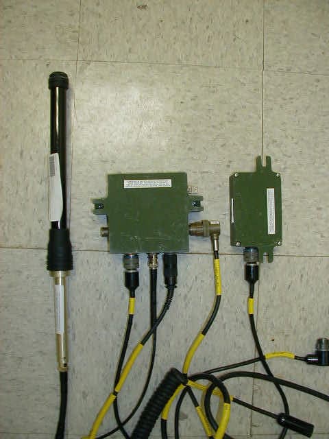
Apr 15, 2003Universal Adapter Interface - UAI
Equipment Class
DTS - Digital Transmission System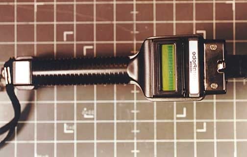
LC3VP
Jul 28, 2002Meter Reader, Versa Probe
Equipment Class
DXX - Part 15 Low Power Communication Device TransmitterLC3780R300
Jul 23, 1995TNB - Licensed Non-Broadcast Station Transmitter
Equipment Class
TNB - Licensed Non-Broadcast Station TransmitterLC3780R400
Jun 07, 1994TNB - Licensed Non-Broadcast Station Transmitter
Equipment Class
TNB - Licensed Non-Broadcast Station Transmitter