LC3VPMeter Reader, Versa Probe
Northrop Grumman Corporation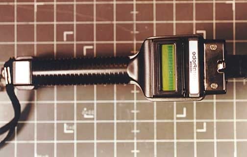
Click to zoom
Application Details
- Equipment Class
- DXX - Part 15 Low Power Communication Device Transmitter
- Date of Grant
- Jul 28, 2002
- Application Purpose
- Original Equipment
- Date of Application
- Jul 28, 2002
- Equipment Note
- Meter Reader, Versa Probe
- Frequency Range
- 0.15360000 - 0.15360000
- Company
- Northrop Grumman Corporation
- Country
- United States
Documents & Files
Document Text
Text extracted from the exhibit documents filed with the FCC. Open a document above to read the original.
Users Manual
NORTHROP GRUMMAN Commercial Information Services 3910 Sorrento Valley Boulevard, Suite A San Diego, CA 92121 1-800-453-0661 VersaProbe ™ Meter Reader USER’S GUIDE July 18, 2002 2 TABLE OF CONTENTS TITLE PAGE 1.0 VersaProbe ™ Environmental Considerations.............................................3 2.0 VersaProbe ™ Operations...........................................................................3 3.0 Selecting VersaProbe ™ Encoder Protocols.................................................4 4.0 AutoSense Mode Selection.........................................................................6 5.0 Reading Meters with the VersaProbe ™ ........................................................7 5.1 The Reading Procedure...................................................................7 5.2 Stored Readings..............................................................................8 6.0 Recharging the VersaProbe ™ Battery Pack..................................................10 7.0 Sensus SmartGun ™ Emulation Mode..........................................................10 This device complies with Part 15 of the FCC Rules. Operation is subject to the following two conditions: (1) this device may not cause harmful interference, and (2) this device must accept any interference received, including interference that may cause undesired operation. This equipment has been tested and found to comply with the limits for a Class B digital device, pursuant to Part 15 of the FCC Rules. These limits are designed to provide reasonable protection against harmful interference in a residential installation. This equipment generates, uses and can radiate radio frequency energy and, if not installed and used in accordance with the instructions, may cause harmful interference to radio communications. However, there is no guarantee that interference will not occur in a particular installation. If this equipment does cause harmful interference to radio or television reception, which can be determined by turning the equipment off and on, the user is encouraged to try to correct the interference by one or more of the following measures: -- Reorient or relocate the receiving antenna. -- Increase the separation between the equipment and receiver. -- Connect the equipment into an outlet on a circuit different from that to which the receiver is connected. -- Consult the dealer or an experienced radio/TV technician for help. Changes or modifications to the VersaProbe not expressly approved by Northrop Grumman could void the user's authority to operate the equipment as a Class B device under Part 15 of the FCC rules. 3 1.0 VersaProbe ™ Environmental Considerations The VersaProbe is designed to operate from –20 to +50 deg C (0-130 deg F), but note that the display may be darker than normal at high temperatures and that the display response may be slower than normal at low temperatures. These changes in display characteristics are normal. Caution: Reasonable care should be taken not to subject the VersaProbe to Electrostatic Discharge (ESD). While normal human- body ESD will not cause physical damage to the VersaProbe, it may cause the probe to switch operating modes or change configuration parameters. When no communication or charging cable is attached to the VersaProbe’s connector, the supplied cap should be attached to the connector to prevent accidental discharge from reaching the connector contacts. 2.0 VersaProbe ™ Operations The VersaProbe is designed for the sole purpose of reading commercially-available direct-connect and inductively coupled utility meter register/encoders. The VersaProbe will display the ID and reading of the register on it’s built-in LCD display and optionally record and/or transmit the data to an external device via an RS-232 data cable. During normal use a VersaProbe operator can perform six primary functions: 1. Select a register/encoder protocol manually. 2. Change between AutoSense and manual modes. 3. Read a meter register/encoder. 4. Transfer collected data from the VersaProbe to an external device. 5. Recharge the VersaProbe battery pack. 6. Enable or disable internal data storage. Each of the first three functions is initiated solely by the operator pressing the trigger button, as will be described later. The last three functions require connection of a data cable or recharging cable to the VersaProbe. Shielded cables are not required for use with the VersaProbe, but any cable connected to the VersaTerm must be less than 2 meters in length to ensure compliance with Part 15 of the FCC rules for Class B devices. 4 3.0 Selecting VersaProbe ™ Encoder Protocols The VersaProbe is capable of reading data from different types of encoder using their respective data transfer protocols. The list of register type protocols include: 1. Master Meter (or Badger) Dialog protocol for single encoders connected to a single meter (not on a network) 2. Master Meter (or Badger) Dialog protocol for multiple encoders connected to multiple meters on a network. 3. Schlumberger ProRead ARB-6 (ProRead) protocol. 4. ABB Water Meters (Kent) ScanCoder protocol. 5. Sensus (Invensys) TouchRead protocol. 6. Schlumberger (Neptune) ARB-1 through ARB-5 7. Hexagram protocol (includes Hersey Touchless) 8. Fusion (SystemEquity) protocol 9. GWF (IEC 1107) protocol 10. CICASA Scanpro protocol 11-15 Reserved for future expansion To select a protocol using the VersaProbe, press and hold the trigger button. If AutoSense is not enabled, the VersaProbe display will initially (for the first second that the trigger button is held down) look something like the example below. DIALOG indicates the current protocol selection. The dash (–) indicates that data storage is turned off, and the 100 indicates that 100% of the VersaProbe's internal memory is empty (available for storage of meter readings). -100 DIALOG If AutoSense is enabled the display may initially look something like this instead, where the added A indicates that AutoSense…
Text truncated - open the document above for the full version.
ID Label/Location Info
Company: Northrop Grumman Corporation FCC registration number: 0003-8001-33 Equipment Name: Meter Reader Model: VersaProbe FCC ID: LC3VP PRODUCT DESCRIPTION The VersaProbe meter reader is a device that reads water and gas meters equipped with wired electronic remote register readout devices. Meters having remote register readout fall into three principal categories: wired DC communication, wired AC communication with transformer coupling, and wireless radio communication. The VersaProbe addresses only the wired DC communication and the wired AC (with transformer coupling) communication categories. The attached block diagram (VPblock.pdf) depicts the functional blocks of the VersaProbe and enumerates the power transmission and signal frequencies present at each point within the circuit. The “antenna” coil in the VersaProbe is not an RF antenna in the traditional sense. It is instead half of the transformer used with meter registers that require the transformer- coupled wired AC signaling method. The other half of the transformer is permanently attached to the meter via a two-conductor cable that may be up to 100 ft long, and is usually mounted in a location having public access such as on the outside wall of a home. The two parts of the transformer must be held in very close physical proximity (0-1 cm) by the operator for the transformer to function. The “antenna” coil is internal to the VersaProbe and is not user-replaceable. Some types of transformer-coupled meters have no internal electrical power source, but instead are supplied power via the coupling transformer. The “transmitter” in the VersaProbe supplies power to such meters via its “antenna” coil during the reading operation only. At all other times the meter is powered mechanically by the flow of the commodity being measured. AC transformer-coupled meters having internal battery power respond to a low-level 154 kHz AC interrogation trigger signal from the VersaProbe, in a half-duplex communication mode, with a low-level 160 kHz AM-modulated AC data signal. AC transformer-coupled meters without battery power receive a high-level AC power carrier from the VersaProbe, in the frequency range of 10.2–28.6 kHz, and respond in one of two ways: either they modulate their resistive loading of the power carrier in a manner that communicates the register data, or they transmit a low-level 28 kHz AC return signal during momentary interruptions of the power carrier (using capacitively stored energy). For reading wired DC meters, the VersaProbe provides an industry-standard electromechanical connector for making connection to wired DC communication registers. This connector may be omitted from a VersaProbe if a customer does not require it. DC direct-coupled meters are supplied with DC power from the VersaProbe. They transmit a single binary bit of data back to the VersaProbe each time the DC power is interrupted momentarily. FCC & CE LABELS Sample ID labels (actual size 25mm W x 16mm H): Material: Aluminized mylar. The front label will be adhered Front label Rear label to the lower label boss on the front side of the VersaProbe, in lieu of the blank label depicted in the attached front photograph. This same photograph also depicts the Model / Manufacturer label adhered to the upper label boss (above the LCD display) on the front side of the VersaProbe. The rear label will be adhered to the lower boss on the rear side of the VersaProbe, in lieu of the blank label depicted in the attached rear photograph. The object above the Model / Manufacturer label on the front and above the circular antenna coil on the rear is an optional meter interface connector for direct-connect meter registers. This connector is omitted on some assemblies and therefore is not available as a labeling surface. VersaProbe Front VersaProbe Rear SERIAL NO. VP14A12345 FCC ID: LC3VP
Test Report
Page 1 of 43 Report No.: FC02-054A ADDENDUM TO FC02-054 FOR THE METER READER, VERSA PROBE FCC PART 15 SUBPART C SECTIONS 15.207 & 15.209 COMPLIANCE DATE OF ISSUE: JULY 25, 2002 PREPARED FOR: Northrop Grumman Corporation 3910 Sorrento Valley Blvd., Suite A San Diego, CA 92121 PREPARED BY: Mary Ellen Clayton CKC Laboratories, Inc. 5473A Clouds Rest Mariposa, CA 95338 P.O. No.: 58890U W.O. No.: 78304 Date of test: June 24-28, 2002 Report No.: FC02-054A This report contains a total of 43 pages and may be reproduced in full only. Partial reproduction may only be done with the written consent of CKC Laboratories, Inc. The results in this report apply only to the items tested, as identified herein. Page 2 of 43 Report No.: FC02-054A TABLE OF CONTENTS Administrative Information ............................................................................................. 4 Summary of Results......................................................................................................... 5 Conditions for Compliance.............................................................................................. 5 Approvals......................................................................................................................... 5 Equipment Under Test (EUT) Description...................................................................... 6 15.31 Number Of Channels ............................................................................................. 6 15.33 Frequency Ranges Tested ...................................................................................... 6 15.35 Analyzer Bandwidth Settings Per Frequency Range............................................. 6 15.203 Antenna Requirements ........................................................................................ 6 15.205 Restricted Bands .................................................................................................. 6 Eut Operating Frequency................................................................................................. 6 Equipment Under Test..................................................................................................... 7 Peripheral Devices ........................................................................................................... 7 Report of Measurements.................................................................................................. 8 Table 1: 15.209 - Fundamental Emission Levels ................................................ 8 Table 2: 15.31(e) - Voltage Variations ................................................................ 9 Table 3: 15.207 - Six Highest Conducted Emission Levels ................................ 10 Table 4: 15.209 - Six Highest Radiated Emission Levels ................................... 11 15.205 Band Edge Ambient................................................................................. 12 15.205 Band Edge Fundamental.......................................................................... 13 Measurement Uncertainty................................................................................................ 14 EUT Setup .......................................................................................................................14 Correction Factors ........................................................................................................... 14 Table A: Sample Calculations ............................................................................. 14 Test Instrumentation and Analyzer Settings.................................................................... 15 Spectrum Analyzer Detector Functions............................................................... 15 Peak ......................................................................................................... 15 Quasi-Peak............................................................................................... 15 Average.................................................................................................... 15 EUT Testing ....................................................................................................................16 Mains Conducted Emissions ............................................................................... 16 Radiated Emissions ............................................................................................. 16 Appendix A: Test Setup Photographs ............................................................................. 17 Photograph Showing Voltage Variations ............................................................ 18 Photograph Showing Mains Conducted Emissions............................................. 19 Photograph Showing Mains Conducted Emissions............................................. 20 Photograph Showing Radiated Emissions ........................................................... 21 Photograph Showing Radiated Emissions ........................................................... 22 Photograph Showing Radiated Emissions ........................................................... 23 Photograph Showing Radiated Emissions ........................................................... 24 Page 3 of 43 Report No.: FC02-054A Photograph Showing Radiated Emissions ........................................................... 25 Photograph Showing Radiated Emissions ........................................................... 26 Appendix B: Test Equipment List ................................................................................... 27 Appendix C: Measurement Data Sheets .......................................................................... 28 Page 4 of 43 Report No.: FC02-054A CKC Laboratories, Inc. has received Certificates of Accreditation from the following agencies: A2LA (USA); DATech (Germany); BSMI (Taiwan); Nemko (Norway); and GOST (Russia). CKC Laboratories, Inc has received test site Registra…
Text truncated - open the document above for the full version.
Test Setup Photos
PHOTOGRAPH SHO WING VOLTAGE VARIATIONS Voltage Variations PHOTOGRAPH SHO WING MAINS CONDUCTED EMISSIONS Mains Conducted Emissions - Front View PHOTOGRAPH SHO WING MAINS CONDUCTED EMISSIONS Mains Conducted Emissions - Back View PHOTOGRAPH SHOWING RADIATED EMISSIONS Radiated Emissions - Front View - Loop Antenna PHOTOGRAPH SHOWING RADIATED EMISSIONS Radiated Emissions - Back View - Loop Antenna PHOTOGRAPH SHOWING RADIATED EMISSIONS Radiated Emissions - Front View - Bicon and Log Periodic Antennas PHOTOGRAPH SHOWING RADIATED EMISSIONS Radiated Emissions - Back View – Bicon and Log Periodic Antennas PHOTOGRAPH SHOWING RADIATED EMISSIONS Radiated Emissions - Front View - H-Probe Antenna PHOTOGRAPH SHOWING RADIATED EMISSIONS Radiated Emissions - Back View - H-Probe Antenna
Contact Information
Applicant
Rod Fremd
Technical Contact
CKC Laboratories, Inc.Mary Ellen Clayton
[email protected]209-966-5240
5473A Clouds Rest · Mariposa, California · United States
Non-Technical Contact
CKC Laboratories, Inc.Mary Ellen Clayton
[email protected]209-966-5240
Test Firm
CKC Laboratories, Inc.Steve Behm
Technical Specifications
| # | Rule Parts | Frequency Range | Power Output |
|---|---|---|---|
| 2 | 15C | 0.1536 MHz - 0.1536 MHz | - |
Other Applications from Northrop Grumman Corporation
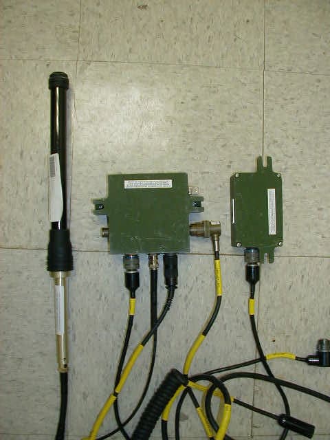
LC3817R191G01
Apr 15, 2003Universal Adapter Interface - UAI
Equipment Class
DTS - Digital Transmission System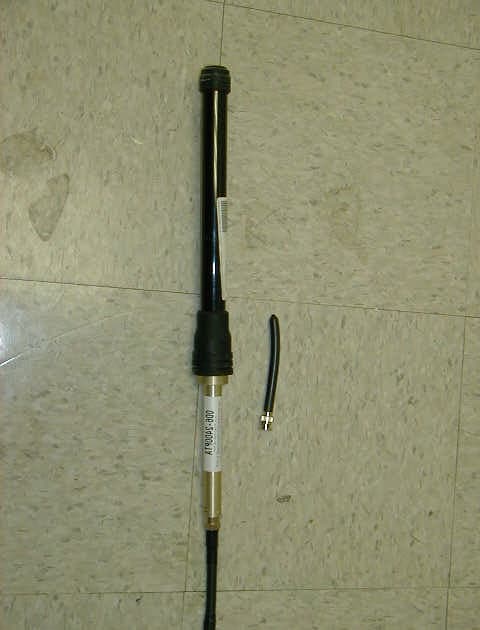
LC3810R901G01
Apr 15, 2003Personal Communication Unit - PCU
Equipment Class
DTS - Digital Transmission SystemLC3780R300
Jul 23, 1995TNB - Licensed Non-Broadcast Station Transmitter
Equipment Class
TNB - Licensed Non-Broadcast Station TransmitterLC3780R400
Jun 07, 1994TNB - Licensed Non-Broadcast Station Transmitter
Equipment Class
TNB - Licensed Non-Broadcast Station Transmitter