LD7JCMTRFID MODULE
Xerox Corporation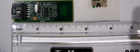
Click to zoom
Application Details
- Equipment Class
- DXX - Part 15 Low Power Communication Device Transmitter
- Date of Grant
- Nov 15, 2005
- Application Purpose
- Original Equipment
- Date of Application
- Nov 15, 2005
- Equipment Note
- RFID MODULE
- Frequency Range
- 13.56000000 - 13.56000000
- Company
- Xerox Corporation
- Country
- United States
Documents & Files
Document Text
Text extracted from the exhibit documents filed with the FCC. Open a document above to read the original.
Cover Letter(s)
TIMCO ENGINEERING, INC. 849 N.W. State Road 45 P.O. Box 370 Newberry, Florida 32669 Date: October 26, 2005 RE: FCC ID: LD7JCMT Dear Reviewer: The following items are intended to show compliance with the requirements for a Part 15 modular transmitter approval for the 13.56 MHz transmitter under consideration in this filing. 1. The modular transmitter will be shielded inside the host units. Since this unit will be installed in Xerox printers control of this shielding will be maintained by the grant holder. Please reference the operational description to see the shielding plate the module will be attached to and the normal position inside the host during a typical installation. 2. The modular transmitter only has data inputs inductively coupled via the toner cartridge tag assembly. This will ensure that no conditions of excessive data rates or over-modulation can occur. 3. The modular transmitter receives its DC power from a regulated supply from within the host and has an on board regulator as well. 4. The transmitter has an integral antenna. 5. The transmitter was tested in a stand-alone configuration. 6. The transmitter is labeled with its own FCC ID. The users manual contains instructions for host unit exterior labeling to use: “Contains FCC ID:” 7. The transmitter complies with all operating requirements applicable to the transmitter. 8. The transmitter complies with applicable RF exposure requirements. If there are additional questions please contact SIEMIC Laboratories at 408-526-1188. Sincerely Gary E. Myers Xerox EMC Manager
Cover Letter(s)
Siemic Laboratories Accessing Global Markets 2206 Ringwood Avenue, San Jose, CA 95131, USA, +1(408)526 1188, +1(408)526 1088, [email protected] Timco Engineering, Inc. 849 N.W. State Road 45 P.O. Box 370 Newberry, Florida 32669 USA 26 October 2005 RE: Confidentiality Request Dear Reviewer: This letter is a request for confidentiality for specific exhibits in reference to The Watt Stopper, Inc. filing for the JCMT under the FCC ID: LD7JCMT. The following exhibits are requested to be held in confidentiality and withheld from public inspection pursuant to 47 CFR 0.457(d): Schematics Block Diagrams Operational Description Users Manual These exhibits contain details of the proprietary operation of the product. These details are not readily discernible from the hardware, constitute trade secrets, and are not generally accessible by the public. This module is not intended for OEM re-sale and the Users Manual is a document internal to Xerox only. We request that the above documents and this letter be withheld from public inspection. Please contact us if further justification for any of the above exhibits is necessary. Sincerely, Alvin Ilarina
Cover Letter(s)
Correspondence Summary Q & A November 16, 2005 SUBJECT: XEROX COPRORATION - FCC ID: JD7JCMT 1. Question about additional justification needed for Modular approval - RF shield requirement of item 1 of DA001407. Answer: The module complies with the radiated emissions requirements for the applicable rule parts in its current state. Additional shielding to satisfy these requirements is not necessary. Furthermore, this particular module has a specific installation configuration. The module will be attached to the metal L-bracket as shown in the operational description. The purpose of the module will be to exchange information with the toner bottle inside a copier or printer. As a result the side of the module not facing the L- bracket will be facing the toner cartridge. The typical implementation of this module will be such that there no cables directly over or under the module that may be coupled to. Please reference the user manual to see the typical installation of the module. Additionally, the relatively low power intentionally radiated by the equipment should also help to reduce the probability of unintended coupling within host devices. TIMCO ENGINEERING INC. 849 NW State Road 45 Newberry, Florida 32669 http://www.timcoengr.com 888.472.2424 F 352.472.2030 [email protected]
External Photos
External Photos Top Bottom
ID Label/Location Info
ID Labeling/Location Information Label Location Label Sample Label Location FCC ID: LD7JCMT IC #: 482B-JCMT
Internal Photos
Internal Photos Top Bottom
Test Report
EMC Test Report Number: EMC05005 EMC Test Group Report Form 24 Rev 3 Page 1 of 22 The Document Company Xerox EMC Test Group FCC Part 15, Subpart C and Industry Canada RSS-210 Compliance Report for Xerox Corporation Short Range Radio Frequency Identification (RFID) Device Model: JCMT Judgement: The Device Under Test (DUT) met the requirements specified in FCC Part 15, Subpart C, Sections 15.207, 15.209 and 15.225, and Industry Canada RSS-GEN, Sections 6 and 7.2.2. The FCC and Industry Canada specified frequency stability tests were not performed as part of this assessment Accreditation Certificate Number: 1248-01 Electrical (EMC) Testing This laboratory is accredited by the American Association for Laboratory Accreditation (A2LA) and the results shown in this test report have been determined in accordance with the laboratory’s terms of accreditation unless stated otherwise in the report. The client is hereby notified that products, materials or other items in this report are in no way approved or endorsed by A2LA unless A2LA explicitly permits such endorsement or approval. EMC Test Report Number: EMC05005 EMC Test Group Report Form 24 Rev 3 Page 2 of 22 Type of Report: Electromagnetic Emissions Compliance Test Report Product: Xerox Corporation RFID Device, Model JCMT Abstract: This report documents the testing completed on an RFID Model JCMT as supplied by the client. The DUT was found to conform with the Federal Communications Commission, and Industry Canada regulatory limits for an intentional radiator and low power licence-exempt radiocommunication device, respectively. FCC is an acronym for “Federal Communications Commission. The FCC acronym is used throughout the document in lieu of the CFR 47 Part 15 Subpart C terminology. The IC acronym is used throughout the document in lieu of the Industry Canada RSS-GEN and RSS-210 terminology. Laboratory: Xerox Corporation Client: Heiko Rommelmann EMC Test Group Xerox Corporation 800 Salt Road Building 843 XSBG/SDU/PCDU Mail Stop 843-16S 800 Phillips Road Building 201 Webster, NY 14580 Mail Stop 201-03S (585) 422-4120 Webster, NY 14580 (585) 422-6449 (fax) (585) 422-0632 (585) 422-9311 (fax) Notice to Client: This report shall not be reproduced, except in full, without the written approval of the EMC Test Group. The client is hereby notified that the results of this report relate only to the item(s) tested. The client is responsible for ensuring that the appropriate information relating to the configuration of the product tested is documented and retained for future reference in accordance with CFR 47 Parts 2 & 15. The client is also responsible for ensuring the product is properly labeled and the customer documentation has the appropriate statements as noted in FCC Parts 2 and 15, and sections 5.10 and 5.11 of Industry Canada RSS-GEN and RSS-210. By signing below, the client certifies that the report distribution and product configuration documented in this test report is correct and that any modifications to the product noted in Section 2.6 shall be incorporated into all production units of the equipment for which this test report has been written. Client: Heiko Rommelmann Date: 11/15/05 Heiko Rommelmann, Product Manager Prepared By: David Spencer Date: 11/15/05 David Spencer, EMC Engineer DSSG / EH&S / EMC Test Group Approved By: Date: 11/15/05 Gary E. Myers, Manager DSSG / EH&S / EMC Group Distribution: Heiko Rommelmann 0201-03S David Spencer 843-16S Gary Myers 843-16S EMC Test Report Number: EMC05005 EMC Test Group Report Form 24 Rev 3 Page 3 of 22 Table of Contents 1 GENERAL INFORMATION................................................................................................................4 1.1 Product Description......................................................................................................................................................................4 1.2 Related Reports / Approvals........................................................................................................................................................4 1.3 Tested System Details....................................................................................................................................................................5 1.3.1 Host Equipment.....................................................................................................................................................................5 1.4 Test Methodology / Reference Standards....................................................................................................................................5 1.5 Test Facility....................................................................................................................................................................................5 2 SYSTEM TEST CONFIGURATION...................................................................................................6 2.1 Justification....................................................................................................................................................................................6 2.2 Run Mode(s)..................................................................................................................................................................................6 2.3 Video Mode Justification..............................................................................................................................................................6 2.4 DUT Exercise Software.................................................................................................................................................................6 2.5 Special Accessories........................................................................................................................................................................6 2.6 Equipment Modifications......................................…
Text truncated - open the document above for the full version.
Test Setup Photos
Test Setup Photos Radiated Emissions Frequency Stability – Temperature Frequency Stability – Voltage Variations
Contact Information
Applicant
Gary E Myers(Technical Specialist)
Test Firm
TUV Rheinland of North AmericaDavid Lanski
[email protected](585) 357-6044
Technical Specifications
| # | Rule Parts | Frequency Range | Power Output |
|---|---|---|---|
| 1 | 15C | 13.56 MHz - 13.56 MHz | - |
Other Applications from Xerox Corporation
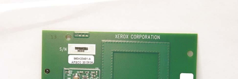
LD7IGEN
Dec 20, 200713.56 RFID Module
Equipment Class
DXX - Part 15 Low Power Communication Device Transmitter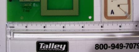
LD7TLST
Nov 16, 2005RFID MODULE
Equipment Class
DXX - Part 15 Low Power Communication Device TransmitterLD7XNA-1
Oct 28, 1997JBP - Part 15 Class B Computing Device Peripheral
Equipment Class
JBP - Part 15 Class B Computing Device PeripheralLD7XTA-1
Jan 26, 1997JBP - Part 15 Class B Computing Device Peripheral
Equipment Class
JBP - Part 15 Class B Computing Device PeripheralLD7XCA-4
Jun 04, 1995Printer
Equipment Class
JBP - Part 15 Class B Computing Device Peripheral