LDV-BBZIGBEEEthernet to ZigBee Bridge/Gateway
Panamax LLC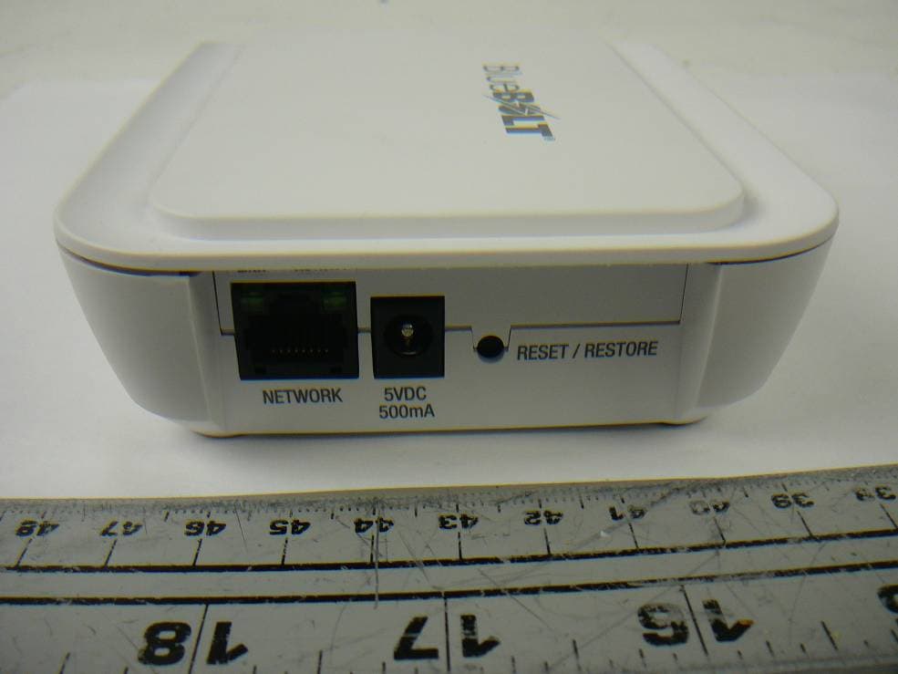
Click to zoom
Application Details
- Equipment Class
- DTS - Digital Transmission System
- Date of Grant
- Jul 13, 2012
- Application Purpose
- Original Equipment
- Date of Application
- Jul 13, 2012
- Equipment Note
- Ethernet to ZigBee Bridge/Gateway
- Frequency Range
- 2405.00000000 - 2465.00000000
- Company
- Panamax LLC
- Country
- United States
Documents & Files
Document Text
Text extracted from the exhibit documents filed with the FCC. Open a document above to read the original.
Users Manual
FOR POSITIONING ONLY (FPO) MAC ADDRESS LABEL (2.4 in. x 0.85 in.) (FPO) ATE CODE SERIAL NUMBER LABEL (1.6 in. x 0.6 in.) MODEL NO: BB-ZIGBEE This device complies with part 15 FCC rules. Operation is subject to the following two conditions: (1) This device may not cause harmful interference. (2) This device must accept any interference received including interference that may cause undesired operation. NO USER SERVICEABLE PARTS INSIDE. RETURN TO PANAMAX IF SERVICE IS REQUIRED. USE ONLY INDOORS. Designed in USA Made in China PANAMAX LLC, PETALUMA, CA (800) 472-5555 www.mybluebolt.com, www.panamax.com RATING: 5VDC, 500mA FCC ID: LDV-BBZIGBEE IC ID: 10379A-BBZIGBEE NET. ZIGBEE BB-ZigBee Quick Start Guide NETWORK 5VDC 500mA RESET / RESTORE NETWORK 5VDC 500mA RESET / RESTORE www.panamax.com www.mybluebolt.comwww.furmansound.com NET. ZIGBEE 1. BB-ZIGBEE 2. Vertical Mount Stand 3. Power Cord & Transformer 4. LAN Cable - CAT5E Package Includes: ATTENTION: PLEASE RETAIN MAC ADDRESS IDENTIFICATION NUMBER AND CHALLENGE KEY, WHICH APPEARS ON THE BACK PANEL OF THE BB- ZigBee. This is unique to every BB-ZigBee unit and will be required for registration. It is recommended that you read the entire list of instructions before proceeding. Installation: • BB-ZigBee must be located in a relatively open area so that radio signal is not blocked. • Unit may be mounted flat or vertically using the sup- plied stand. Can also be wall mounted or equipment rack mounted using keyhole slots on back of product. • Connect power cord to BB-ZigBee and wall outlet. • Connect LAN Cable from router to BB-ZigBee. NETWORK 5VDC 500mA RESET / RESTORE Router NETWORK 5VDC 500mA RESET / RESTORE • RED LED: No network established. See troubleshooting. AC Power LAN Cable • Flashing Green LED: Indicates mode to allow an end-user device to join the network. Ethernet indicators: NETWORK 5VDC 500mA RESET / RESTORE Reset Button for System Reset: • If the reset button is pressed for less than 8 seconds, the system goes to startup mode. • If thereset button is pressed for more than 8 seconds, the system restores all factory settings and goes to startup mode. Online Registration: Your BlueBOLT™ enabled Power Management Component is completely plug-and-play and does not require any software installation. The BlueBOLT™ control interface is operated through your web browser. 1) Using any Internet connected computer, go to www. mybluebolt.com using your standard Internet browser. 2) Follow the on screen instructions to create an account and/or take control of your BlueBOLT™ enabled product. Note: you will need the BlueBOLT- BB-ZigBee’s unique MAC address and challenge key (provided on the card’s protective packaging as well as on the label of the card itself) in order to register the unit online. • ACTIVITY: Data Activity on Ethernet Connection • LINK: Valid Ethernet Connection NET. Network Indicator: Indicates status of Internet connection. • BLUE LED: Connection to network and BlueBOLT established. • GREEN LED: Connection to network established, but connection to BlueBOLT not established. See trouble- shooting guide. ZIGBEE NET. NET. Zigbee indicator: Indicates status of ZigBee network. • LED is Off: Not jpined to any ZigBee network. • Green LED: ZigBee Active ZIGBEE ZIGBEE DQS-00008-B Troubleshooting Your BlueBOLT™ enabled Power Management Component (BB-ZigBee) is completely plug- and-play and does not require any software installation. The BlueBOLT™ control interface is operated through your web browser. 1) Using any Internet connected computer, go to www.mybluebolt.com using your standard Internet browser. 2) Follow the on screen instructions to create an account and/or take control of your BlueBOLT™ enabled product. Note: you will need the BB-ZigBee’s unique MAC address and challenge key (provided on the label on the back of BB-ZigBee) in order to register the unit online. 3) If BlueBOLT™ cannot detect your device within 20 seconds of inputting your MAC address and challenge key, please follow the on-screen troubleshooting guide. Also confirm the BB-ZigBee is properly connected to the Internet. Panamax LLC, 1690 Corporate Circle, Petaluma, CA 94954 707-283-5900 • 800-472-5555 • www.panamax.com • www.mybluebolt.com ©2012 Panamax LLC, Panamax, Furman and BlueBOLT logos are US registered trademarks of Panamax www.panamax.com www.mybluebolt.comwww.furmansound.com SERVICE If you require technical support or equipment service, please contact the Service Department at 1-800-472-5555. All equipment being returned for repair must have a Return Authorization (RA) number. To get an RA number, call the Customer Service Department. Before returning any equip- ment for repair, be sure that it is adequately packed and cushioned against damage in ship- ment, and that it is insured. We suggest that you save the original packaging and use it to ship the product for servicing. Also, please provide a note with your name, address, phone number, RA number and a description of the problem. LIMITED 1 YEAR WARRANTY Panamax/Furman Limited Product Warranty: Panamax Inc. warrants to the purchaser of this product for a period of one (1) year from the date of purchase, that the unit shall be free of defects in design, material or workmanship, and Panamax Inc. will repair or replace any defective unit. Full warranty information is available online at www.Panamax.com or www.FurmanSound.com. FCC CLASS B DIGITAL DEVICE INFORMATION NOTE: This equipment has been tested and found to comply with the limits for a Class B digital device, pursuant to part 15 of the FCC Rules and Industry Canada license-exempt RSS Standard(s). These limits are designed to provide reason- able protection against harmful interference in a residential installation. This equipment generates, uses and can radiate radio frequency energy and, if not installed and used in accordance with the instructions, may cause harmful interference to radio communications. However, there is no guar- antee that interfer…
Text truncated - open the document above for the full version.
External Photos
Panamax, LLC FCC ID: LDV-BBZIGBEE, IC: 10379A-BBZIGBEE Report Number: R1205101-247 Page 50 of 54 FCC Part 15C/IC RSS-210 Test Report 16 Exhibit C – EUT Photographs 16.1 EUT – Front View 16.2 EUT – Rear View Panamax, LLC FCC ID: LDV-BBZIGBEE, IC: 10379A-BBZIGBEE Report Number: R1205101-247 Page 51 of 54 FCC Part 15C/IC RSS-210 Test Report 16.3 EUT – Top View 16.4 EUT – Bottom View Panamax, LLC FCC ID: LDV-BBZIGBEE, IC: 10379A-BBZIGBEE Report Number: R1205101-247 Page 52 of 54 FCC Part 15C/IC RSS-210 Test Report 16.5 EUT – Side View (1) 16.6 EUT – Side View (2)
ID Label/Location Info
FOR POSITIONING ONLY (FPO) MAC ADDRESS LABEL (2.4 in. x 0.85 in.) (FPO) ATE CODE SERIAL NUMBER LABEL (1.6 in. x 0.6 in.) BACK PANEL - PRINTING COLOR PANTONE COOL GRAY #10 MODEL NO: BB-ZIGBEE RATING: 5VDC, 500mA FCC ID: LDV-BBZIGBEE IC: 10379A-BBZIGBEE This device complies with part 15 FCC rules. Operation is subject to the following two conditions: (1) This device may not cause harmful interference. (2) This device must accept any interference received including interference that may cause undesired operation. NO USER SERVICEABLE PARTS INSIDE. RETURN TO PANAMAX IF SERVICE IS REQUIRED. USE ONLY INDOORS. Designed in USA Made in China PANAMAX LLC, PETALUMA, CA (800) 472-5555 www.mybluebolt.com, www.panamax.com SCREEN PRINT ART FOR PRODUCT MODEL: BB-ZIGBEE BACK Panel - PRINTING COLOR: PANTONE COOL GRAY 10 PART NO. ENS-00042 - REV. B DATE 6/19/12 MODEL NO: BB-ZIGBEE RATING: 5VDC, 500mA FCC ID: LDV-BBZIGBEE IC: 10379A-BBZIGBEE This device complies with part 15 FCC rules. Operation is subject to the following two conditions: (1) This device may not cause harmful interference. (2) This device must accept any interference received including interference that may cause undesired operation. NO USER SERVICEABLE PARTS INSIDE. RETURN TO PANAMAX IF SERVICE IS REQUIRED. USE ONLY INDOORS. Designed in USA Made in China PANAMAX LLC, PETALUMA, CA (800) 472-5555 www.mybluebolt.com, www.panamax.com
Internal Photos
Panamax, LLC FCC ID: LDV-BBZIGBEE, IC: 10379A-BBZIGBEE Report Number: R1205101-247 Page 53 of 54 FCC Part 15C/IC RSS-210 Test Report 16.7 EUT – Main Board Top View 16.8 EUT – Main Board Bottom View Antenna Panamax, LLC FCC ID: LDV-BBZIGBEE, IC: 10379A-BBZIGBEE Report Number: R1205101-247 Page 54 of 54 FCC Part 15C/IC RSS-210 Test Report 16.9 EUT – AC/DC Power Adapter --- END OF REPORT ---
RF Exposure Info
Panamax, LLC FCC ID: LDV-BBZIGBEE, IC: 10379A-BBZIGBEE Report Number: R1205101-247 Page 9 of 54 FCC Part 15C/IC RSS-210 Test Report 4 FCC §15.247 (i), §2.1091 & IC RSS-102 – RF Exposure 4.1 Applicable Standard According to FCC §15.247(i) §1.1307(b)(1) and §1.1310 systems operating under the provisions of this section shall be operated in a manner that ensures that the public is not exposed to radio frequency energy level in excess of the Commission’s guidelines. Limits for General Population/Uncontrolled Exposure Frequency Range (MHz) Electric Field Strength (V/m) Magnetic Field Strength (A/m) Power Density (mW/cm 2 ) Averaging Time (minutes) Limits for General Population/Uncontrolled Exposure 0.3-1.34 614 1.63 * (100) 30 1.34-30 824/f 2.19/f * (180/f 2 ) 30 30-300 27.5 0.073 0.2 30 300-1500 / / f/1500 30 1500-100,000 / / 1.0 30 f = frequency in MHz * = Plane-wave equivalent power density Before equipment certification is granted, the procedure of IC RSS-102 must be followed concerning the exposure of humans to RF fields. According to IC RSS-102 Issue 2 section 4.1, RF limits used for general public will be applied to the EUT. Frequency Range (MHz) Electric Field (V/m rms) Magnetic Field (A/m rms) Power Density (W/m 2 ) Time Averaging (min) 0.003 - 1 280 2.19 - 6 1 - 10 280 / f 2.19 / f - 6 10 - 30 28 2.19 / f - 6 30 – 300 28 0.073 2* 6 300 – 1 500 1.585 f 0.5 0.0042 f 0.5 f / 150 6 1 500 – 15 000 61.4 0.163 10 6 15 000 – 150 000 61.4 0.163 10 616000 / f 1.2 150 000- 300 000 0.158 f 0.5 4.21 x 10 -4 f 0.5 6.67 x 10 -5 f 616000 / f 1.2 Note: ƒ is frequency in MHz * = Power density limit is applicable at frequencies greater than 100 MHz Panamax, LLC FCC ID: LDV-BBZIGBEE, IC: 10379A-BBZIGBEE Report Number: R1205101-247 Page 10 of 54 FCC Part 15C/IC RSS-210 Test Report 4.2 MPE Prediction Predication of MPE limit at a given distance, Equation from OET Bulletin 65, Edition 97-01 S = PG/4πR² Where: S = power density P = power input to antenna G = power gain of the antenna in the direction of interest relative to an isotropic radiator R = distance to the center of radiation of the antenna 4.3 MPE Results Maximum peak output power at antenna input terminal (dBm):20.25 Maximum peak output power at antenna input terminal (mW): 105.93 Prediction distance (cm): 20 Prediction frequency (MHz): 2440 Maximum Antenna Gain, typical (dBi): 0 Maximum Antenna Gain (numeric): 1.0 Power density of prediction frequency at 20.0 cm (mW/cm 2 ):0.021 Power density of prediction frequency at 20.0 cm (W/m 2 ):0.21 MPE limit for uncontrolled exposure at prediction frequency (mW/cm 2 ):1.0 MPE limit for uncontrolled exposure at prediction frequency (W/m 2 ):10 The device is compliant with the requirement MPE limit for uncontrolled exposure. The maximum power density at the distance of 20 cm is 0.021 mW/cm 2 (0.21 W/m 2 ).Limit is 1.0 mW/cm 2 (10 W/m 2 ).
Test Report
Note: This test report is prepared for the customer shown above and for the device described herein. It may not be duplicated or used in part without prior written consent from Bay Area Compliance Laboratories Corp. This report must not be used by the customer to claim product certification, approval, or endorsement by A2LA*, NIST, or any agency of the Federal Government. * This report may contain data that are not covered by the A2LA accreditation and are marked with an asterisk “*” (Rev.2) FCC PART 15 SUBPART C IC RSS-210, ISSUE 8, DECEMBER 2010 TEST AND MEASUREMENT REPORT For Panamax, LLC 1690 Corporate Circle, Petaluma, CA 94954, USA Report Type: Original Report Product Type: Ethernet Bridge(networking device) Prepared By Ning Ma Report Number R1205101-247 Report Date 2012-07-09 Reviewed By Victor Zhang EMC/RF Lead Bay Area Compliance Laboratories Corp. 1274 Anvilwood Avenue, Sunnyvale, CA 94089, USA Tel: (408) 732-9162 Fax: (408) 732-9164 FCC ID: LDV-BBZIGBEE IC: 10379A-BBZIGBEE Panamax, LLC FCC ID: LDV-BBZIGBEE, IC: 10379A-BBZIGBEE Report Number: R1205101-247 Page 2 of 54 FCC Part 15C/IC RSS-210 Test Report TABLE OF CONTENTS 1 General Description..................................................................................................................................................... 5 1.1 Product Description for Equipment Under Test (EUT) ....................................................................................... 5 1.2 Mechanical Description of EUT .......................................................................................................................... 5 1.3 Objective.............................................................................................................................................................. 5 1.4 Related Submittal(s)/Grant(s) .............................................................................................................................. 5 1.5 Test Methodology................................................................................................................................................ 5 1.6 Measurement Uncertainty.................................................................................................................................... 5 1.7 Test Facility......................................................................................................................................................... 6 2 System Test Configuration.......................................................................................................................................... 7 2.1 Justification.......................................................................................................................................................... 7 2.2 EUT Exercise Software ....................................................................................................................................... 7 2.3 Special Equipment ............................................................................................................................................... 7 2.4 Equipment Modifications .................................................................................................................................... 7 2.5 EUT Internal Configuration Details .................................................................................................................... 7 2.6 Power Supply List and Details............................................................................................................................. 7 3 Summary of Test Results ............................................................................................................................................ 8 4 FCC §15.247 (i), §2.1091 & IC RSS-102 – RF Exposure.......................................................................................... 9 4.1 Applicable Standard ............................................................................................................................................ 9 4.2 MPE Prediction.................................................................................................................................................. 10 4.3 MPE Results ...................................................................................................................................................... 10 5 FCC §15.203 & IC RSS-Gen §7.1.2 – Antenna Requirements ................................................................................ 11 5.1 Applicable Standard .......................................................................................................................................... 11 5.2 Antenna List ...................................................................................................................................................... 11 6 FCC §15.207 & IC RSS-Gen §7.2.4 – AC Line Conducted Emissions.................................................................... 12 6.1 Applicable Standards ......................................................................................................................................... 12 6.2 Test Setup .......................................................................................................................................................... 12 6.3 Test Procedure ................................................................................................................................................... 12 6.4 Test Setup Block Diagram................................................................................................................................. 13 6.5 Corrected Amplitude & Margin Calculation ..................................................................................................... 13 6.6 Test Equipment List and Details...........................................................................................…
Text truncated - open the document above for the full version.
Test Setup Photos
Panamax, LLC FCC ID: LDV-BBZIGBEE, IC: 10379A-BBZIGBEE Report Number: R1205101-247 Page 47 of 54 FCC Part 15C/IC RSS-210 Test Report 15 Exhibit B – Test Setup Photographs 15.1 AC Line Conducted Emission Front View 15.2 AC Line Conducted Emission Side View Panamax, LLC FCC ID: LDV-BBZIGBEE, IC: 10379A-BBZIGBEE Report Number: R1205101-247 Page 48 of 54 FCC Part 15C/IC RSS-210 Test Report 15.3 Radiated Emission Front View 15.4 Radiated Emission below 1 GHz Rear View Panamax, LLC FCC ID: LDV-BBZIGBEE, IC: 10379A-BBZIGBEE Report Number: R1205101-247 Page 49 of 54 FCC Part 15C/IC RSS-210 Test Report 15.5 Radiated Emission above 1 GHz Rear View
Contact Information
Applicant
Gerald Hoopes(Engineering Manager)
Test Firm
Bay Area Compliance LaboratoryJohn Chan
Technical Specifications
| # | Rule Parts | Frequency Range | Power Output |
|---|---|---|---|
| 1 | 15C | 2.40 GHz - 2.46 GHz | 106.00 mW |
Other Applications from Panamax LLC
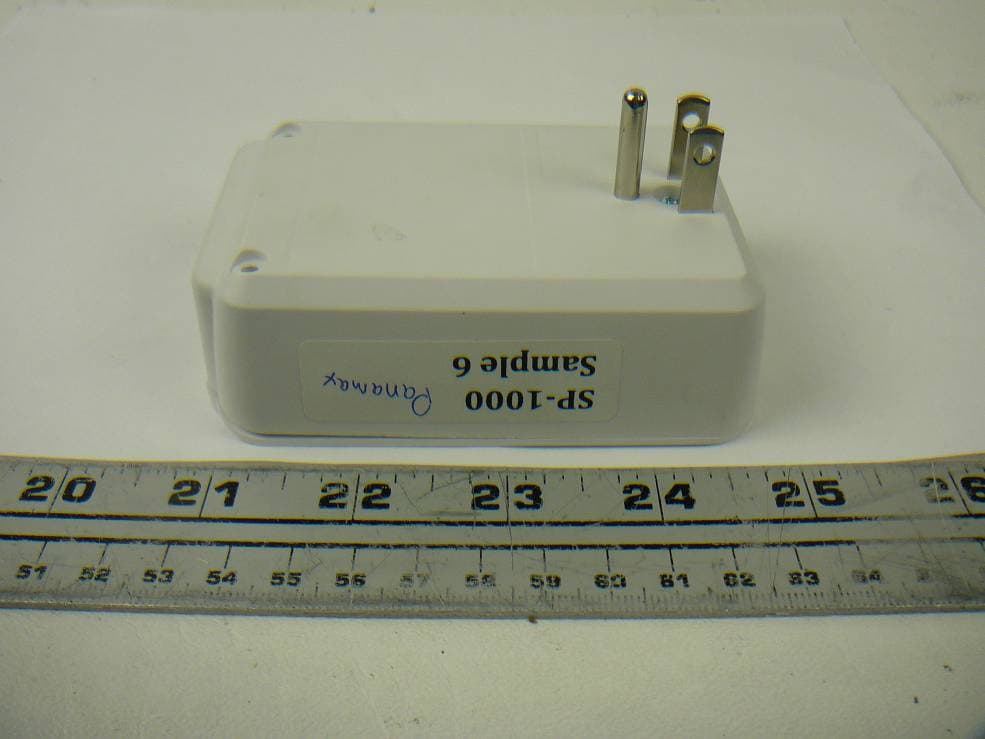
LDV-SP1000
Jul 07, 2012Energy Management Device, ZigBee Wireless
Equipment Class
DTS - Digital Transmission System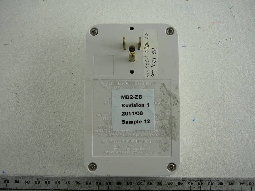
LDVMD2-ZB
Dec 11, 2011ZigBee Load Control Device
Equipment Class
DTS - Digital Transmission System