LDVMD2-ZBZigBee Load Control Device
Panamax LLC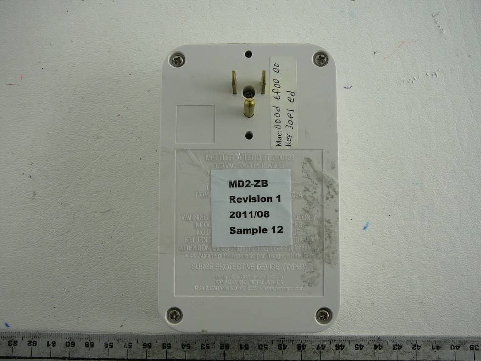
Click to zoom
Application Details
- Equipment Class
- DTS - Digital Transmission System
- Date of Grant
- Dec 11, 2011
- Application Purpose
- Original Equipment
- Date of Application
- Dec 11, 2011
- Equipment Note
- ZigBee Load Control Device
- Frequency Range
- 2405.00000000 - 2475.00000000
- Company
- Panamax LLC
- Country
- United States
Documents & Files
Document Text
Text extracted from the exhibit documents filed with the FCC. Open a document above to read the original.
Users Manual
INSTALLATION INSTRUCTIONS MD2-ZB This device complies with part 15 of the FCC Rules. Operation is subject to the following two conditions: (1) This device may not cause harmful interference, and (2) This device must accept any interference received, including interference that may cause undesired operation. This equipment has been tested and found to comply with the limits for a Class B digital device in accordance with the specifications of Part 15 of FCC rules. These specifications are designed to provide reasonable protection against such interference win a residential installation. However, there is no guarantee that interference will not occur in a particular installation. MD2-ZB OPTIONS FOR MOUNTING & FRONT COVER FACEPLATE Cover can be removed & painted to match color of wall. Do not paint the sides, top or bottom. Warranty will be voided. www.panamax.com www.mybluebolt.com www.furmansound.com www.panamax.com www.mybluebolt.com www.furmansound.com 1 Cover can be flipped around 180 degrees to hide LEDs from front straight-on view if desired. RF / ZigBee ZigBee®/802.15.4 Radio 2.405-2.475 GHz, unlicensed ISM band 3dBm transmitter output -99dBm receiver sensitivity General Weight__________ 0.7lb Dimensions_______ 3.25 in. W X 1.625 in. D X 5.25 in. H Electrical Ratings Line Voltage ______ 120 Vac, 60Hz Current Rating _____ 12 A Voltage Protection Rating (UL 1449 3rd Edition, 3,000A) _________ 400V L-N, 500V L-G, 400V N-G Nominal Discharge Current (UL1449 3rd Edi- tion _____________3,000A Electrical Measurements RMS Voltage ______ 1% precision RMS Current ______ 1% precision Power___________ 2% precision Cumulative Energy__ 2% precision SPECIFICATIONS Unit can be securely screwed into wall outlet faceplate using either hole (2) indicated (screw is included). WARRANTY POLICIES Product Warranty: Limited 3 Year Warranty Connected Equipment Protection Policy: Limited $100,000 Connected Equipment Policy C US AGENCY APPROVALS CCSAUS Certified: UL1449 3rd Edition (Type 3 SPD), CSA C22.2 No. 42 UL 1449 Voltage Protection Rating: 400V L-N, 500V L-G, 400V N-G Cover of MD2-ZB can easily be removed by pulling off cover at the two side indents (1). 2 OUTLET 1 Left side. Ground Pin Out. OUTLET 2 Right side. Ground Pin Down. POWER STATUS INDICATOR LIGHTS Outlet 1 Network Connection Status INDICATOR LIGHTS Outlet 2 Wiring Fault PUSH BUTTONS For Outlet’s Power ON/OFF and Network Connection REMOVABLE COVER FACEPLATE Finger Indent to Pull Off Cover. In accordance with FCC 15.21, changes or modifications not expressly approved by the party responsible for compliance could void the user’s authority to operate the equipment. INSTALLATION B LT Blue ® B LT Blue ® B LT Blue ® B LT Blue ® B LT Blue ® B LT Blue ® 5. If the NETWORK / DEMAND RESPONSE light is RED, the MD2-ZB is not connected to a ZigBee network. Proceed to step 6, SETUP 6. Verify that a BlueBOLT ZigBee, ZigBee- Ethernet Bridge device is powered on and within 100 ft. of an active ZigBee device. 1. Turn OFF the equipment that you are plugging into the MD2-ZB 2. Plug MD2-ZB into the wall outlet. The red “WIRING FAULT” light indicates an im- properly wired outlet that must be checked by a qualified electrician. 4. Press the OUTLET 1 and/or OUTLET 2 buttons to switch power on the respective outlets. 8. On MD2-ZB, press the OUTLET 1 and OUTLET 2 buttons simultaneously. The NETWORK/DEMAND RESPONSE light will turn GREEN once it has joined the network. 7. Through the BlueBOLT interface, enable NETWORK JOINING. Refer to the user manual for BB-ZIGBEE for detailed instructions. 3. Plug your equipment into the AC outlets. SETUP NETWORK CONNECT OUTLET 1 WIRING FAULT NETWORK DEMAND RESP. OUTLET 2 OUTLET 1 OUTLET 2 Multible MD2-ZB units can be installed within 100 ft. from an active ZigBee device (BB-ZIGBEE BRIDGE or MD2-ZB). BB-ZIGBEE MD2-ZB MD2-ZB MD2-ZB NETWORK CONNECT OUTLET 1 WIRING FAULT NETWORK DEMAND RESP. OUTLET 2 OUTLET 1 OUTLET 2 NETWORK CONNECT OUTLET 1 WIRING FAULT NETWORK DEMAND RESP. OUTLET 2 OUTLET 1 OUTLET 2 NETWORK CONNECT OUTLET 1 WIRING FAULT NETWORK DEMAND RESP. OUTLET 2 OUTLET 1 OUTLET 2 100 ft. Maximum 100 ft. Max. 100 ft. Maximum
Cover Letter(s)
/ r I 'I /'// 'I v FCC Confidential Authorization November 18, 2011 FEDERAL COMMUNICATIONS COMMISSIONS Authorization and Evaluation Division 7435 Oakland Mills Road Columbia, MD 21046 Subject: Confidentiality Request regarding application for certification of FCC ID: LDVMD2-ZB In accordance with Sections 0.457 and 0.459 ofthe Commission's Rules, Panamax LLC hereby requests long-term confidential treatment of information accompanying this application as outlined below: © Block Diagram ® Schematics o Operation Description The above materials contain proprietary and confidential information not customarily released to the public. The public disclosure of these materials provides unjustified benefits to its competitors in the market. Sincerely, Humphrey johnh(a>panamax.com (707) 766-2302 I't>! i.-i i< I i' AA ' i , M|[M.,'(I < 't> '• I i '.shii >. i..'•"."-' • v.".AV.pni'.m.;ix.t;om • sou •',.:' .•. . . • FAX /'.<•" AA"- ."i(t|
External Photos
Panamax, LLC FCC ID: LDVMD2-ZB Report Number: R1109151-247 Page 42 of 47 FCC Part 15C Test Report 15 Exhibit C - EUT Photographs 15.1 EUT – Front View 15.2 EUT – Back View Panamax, LLC FCC ID: LDVMD2-ZB Report Number: R1109151-247 Page 43 of 47 FCC Part 15C Test Report 15.3 EUT – Side View (1) 15.4 EUT – Side View (2) Panamax, LLC FCC ID: LDVMD2-ZB Report Number: R1109151-247 Page 44 of 47 FCC Part 15C Test Report 15.5 EUT – Top View 15.6 EUT – Bottom View
Internal Photos
Panamax, LLC FCC ID: LDVMD2-ZB Report Number: R1109151-247 Page 45 of 47 FCC Part 15C Test Report 15.7 EUT – Cover off view 15.8 EUT – RF PCB Assembly Front View Panamax, LLC FCC ID: LDVMD2-ZB Report Number: R1109151-247 Page 46 of 47 FCC Part 15C Test Report 15.9 EUT – RF PCB Assembly Back View 15.10 EUT – Power Supply PCB Assembly Front View Panamax, LLC FCC ID: LDVMD2-ZB Report Number: R1109151-247 Page 47 of 47 FCC Part 15C Test Report 15.11 EUT – Power Supply PCB Assembly Back View 15.12 Supporting Equipment – Ember Insight Development Kit --- END OF REPORT ---
RF Exposure Info
Panamax, LLC FCC ID: LDVMD2-ZB Report Number: R1109151-247 Page 9 of 47 FCC Part 15C Test Report 4 FCC §15.247(i) & §2.1091 - RF Exposure Information 4.1 Applicable Standards According to FCC §15.247(i) and §1.1307(b)(1), systems operating under the provisions of this section shall be operated in a manner that ensures that the public is not exposed to radio frequency energy level in excess of the Commission’s guidelines. According to §1.1310 and §2.1091 RF exposure is calculated. Limits for General Population/Uncontrolled Exposure Frequency Range (MHz) Electric Field Strength (V/m) Magnetic Field Strength (A/m) Power Density (mW/cm 2 ) Averaging Time (minutes) 0.3-1.34 614 1.63 *(100) 30 1.34-30 824/f 2.19/f *(180/f 2 ) 30 30-300 27.5 0.073 0.2 30 300-1500 / / f/1500 30 1500-100,000 / / 1.0 30 f = frequency in MHz * = Plane-wave equivalent power density 4.2 MPE Prediction Predication of MPE limit at a given distance, Equation from OET Bulletin 65, Edition 97-01 S = PG/4πR² Where: S = power density P = power input to antenna G = gain of the antenna in the direction of interest relative to an isotropic radiator R = distance to the center of radiation of the antenna 4.3 MPE Results Maximum peak output power at antenna input terminal (dBm):3.19 Maximum peak output power at antenna input terminal (mW): 2.08 Prediction distance (cm): 20 Prediction frequency (MHz): 2405 Maximum Antenna Gain, typical (dBi): 0 Maximum Antenna Gain (numeric): 1.0 Power density of prediction frequency at 20.0 cm (mW/cm 2 ): 0.0004 MPE limit for uncontrolled exposure at prediction frequency (mW/cm 2 ): 1.0 The device is compliant with the requirement MPE limit for uncontrolled exposure. The maximum power density at the distance of 20 cm is 0.0004 mW/cm 2 , The Limit is 1.0 mW/cm 2.
Test Report
Note: This test report is prepared for the customer shown above and for the device described herein. It may not be duplicated or used in part without prior written consent from Bay Area Compliance Laboratories Corp. This report must not be used by the customer to claim product certification, approval, or endorsement by NVLAP*, NIST, or any agency of the Federal Government. * This report may contain data that are not covered by the NVLAP accreditation and are marked with an asterisk “*” (Rev.2) FCC PART 15, SUBPART C TEST AND MEASUREMENT REPORT For Panamax, LLC 1690 Corporate Circle, Petaluma, CA 94954, USA FCC ID: LDVMD2-ZB Report Type: Original Report Product Type: Energy Management Module with Zigbee Transceiver Test Engineer: Quinn Jiang Report Number: R1109151-247 Report Date: 2011-12-06 Reviewed By: Victor Zhang RF/EMC Lead Prepared By: (SP) Bay Area Compliance Laboratories Corp. 1274 Anvilwood Avenue, Sunnyvale, CA 94089, USA Tel: (408) 732-9162 Fax: (408) 732 9164 Panamax, LLC FCC ID: LDVMD2-ZB Report Number: R1109151-247 Page 2 of 47 FCC Part 15C Test Report TABLE OF CONTENTS 1 GENERAL DESCRIPTION......................................................................................................................................... 5 1.1 PRODUCT DESCRIPTION FOR EQUIPMENT UNDER TEST (EUT)................................................................................. 5 1.2 MECHANICAL DESCRIPTION OF EUT .......................................................................................................................... 5 1.3 OBJECTIVE............................................................................................................................................................... 5 1.4 RELATED SUBMITTAL(S)/GRANT(S) ........................................................................................................................ 5 1.5 TEST METHODOLOGY.............................................................................................................................................. 5 1.6 MEASUREMENT UNCERTAINTY...............................................................................................................................5 1.7 TEST FACILITY........................................................................................................................................................ 6 2 SYSTEM TEST CONFIGURATION .......................................................................................................................... 7 2.1 JUSTIFICATION......................................................................................................................................................... 7 2.2 EUT EXERCISE SOFTWARE...................................................................................................................................... 7 2.3 EQUIPMENT MODIFICATIONS................................................................................................................................... 7 2.4 SPECIAL ACCESSORIES............................................................................................................................................ 7 2.5 POWER SUPPLY AND LINE FILTERS.......................................................................................................................... 7 2.6 LOCAL SUPPORT EQUIPMENT.................................................................................................................................. 7 2.7 INTERFACE PORTS AND CABLING............................................................................................................................ 7 2.8 EUT INTERNAL CONFIGURATION DETAILS.............................................................................................................. 7 3 SUMMARY OF TEST RESULTS ............................................................................................................................... 8 4 FCC §15.247(I) & §2.1091 - RF EXPOSURE INFORMATION............................................................................... 9 4.1 APPLICABLE STANDARDS........................................................................................................................................ 9 4.2 MPE PREDICTION.................................................................................................................................................... 9 4.3 MPE RESULTS......................................................................................................................................................... 9 5 FCC §15.203 - ANTENNA REQUIREMENT........................................................................................................... 10 5.1 APPLICABLE STANDARD........................................................................................................................................ 10 5.2 ANTENNA CONNECTOR CONSTRUCTION................................................................................................................ 10 6 FCC §15.207 – AC LINE CONDUCTED EMISSIONS ........................................................................................... 11 6.1 APPLICABLE STANDARD........................................................................................................................................ 11 6.2 TEST SETUP BLOCK DIAGRAM...............................................................................................................................11 6.3 TEST SETUP........................................................................................................................................................... 11 6.4 TEST PROCEDURE.................................................................................................................................................. 12 6.5 TEST EQUIPMENT LIST AND DETAILS......................................................................................…
Text truncated - open the document above for the full version.
Test Setup Photos
Panamax, LLC FCC ID: LDVMD2-ZB Report Number: R1109151-247 Page 39 of 47 FCC Part 15C Test Report 14 Exhibit B - Test Setup Photographs 14.1 AC Line Conducted Emissions Front View 14.2 AC Line Conducted Emissions Side View Panamax, LLC FCC ID: LDVMD2-ZB Report Number: R1109151-247 Page 40 of 47 FCC Part 15C Test Report 14.3 Radiated Emissions Front View 14.4 Radiated Emissions below 1 GHz Rear View Panamax, LLC FCC ID: LDVMD2-ZB Report Number: R1109151-247 Page 41 of 47 FCC Part 15C Test Report 14.5 Radiated Emissions above 1 GHz Rear View
Contact Information
Applicant
Gerald Hoopes(Engineering Manager)
Test Firm
Bay Area Compliance LaboratoryJohn Chan
Technical Specifications
| # | Rule Parts | Frequency Range | Power Output |
|---|---|---|---|
| 1 | 15C | 2.40 GHz - 2.48 GHz | 2.00 mW |
Other Applications from Panamax LLC
LDV-BBZIGBEE
Jul 13, 2012Ethernet to ZigBee Bridge/Gateway
Equipment Class
DTS - Digital Transmission System
LDV-SP1000
Jul 07, 2012Energy Management Device, ZigBee Wireless
Equipment Class
DTS - Digital Transmission System