LE2APPCAM26PTA720p PT WIFI Camera
JSW Pacific Corporation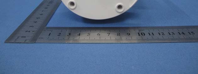
Click to zoom
Application Details
- Equipment Class
- DTS - Digital Transmission System
- Date of Grant
- Jun 13, 2015
- Application Purpose
- Original Equipment
- Date of Application
- Jun 11, 2015
- Equipment Note
- 720p PT WIFI Camera
- Frequency Range
- 2422.00000000 - 2452.00000000
- Company
- JSW Pacific Corporation
- Country
- Taiwan
Documents & Files
Document Text
Text extracted from the exhibit documents filed with the FCC. Open a document above to read the original.
Users Manual
1 Quick-Start Guide Guardian App Cam 26 IP Camera Use this Quick-Start Guide to connect the camera to the network. If you want to set up more cameras later, refer to the online user manual for instructions. In the Box • Camera (x1) • Antenna (x1) • Mounting Bracket (x1) • Ethernet Cable (x1) • AC Adaptor (x1) • Screw Pack • Quick-Start Guide If any item is missing or damaged, contact your place of purchase immediately. Never use damaged products! Need help? Get answers at our website: www.uniden.com.au for Australian model 2 Getting to know your Guardian App Cam 26 1. Do not drop, puncture or disassemble the camera. 2. This camera is NOT waterproof. 3. Never tug on the power cords. Use the plug to unplug it from the wall outlet. 4. Do not expose the camera to high temperature or leave it in direct sunlight. Doing so may damage the camera or cause camera temporary malfunction. 5. For your own safety, avoid using the camera or power off the camera when there is a storm or lightning. 6. Remove the power adaptor during long periods between usages. 7. Use only the accessories and power adaptors supplied. Important Safety Instructions Light Sensor LAN Port Reset Antenna Connector Microphone Infrared LEDs MicroSD Card Slot Status LED Power Input 3 Set Up Camera, Smartphone and Tablet Prerequisites • Your router must support WPA/WPA2 security and it must be turned on. • You must have an available WiFi-enabled mobile device (Android or iOS smartphone/tablet). • The Guardian App Cam 26 and your mobile device must connect to the same WiFi router for setup. 1. Download the Guardian App (search for - Uniden® AppCam™) from the Apple App store (iOS) or Play Store (Android) on to your device. 2. Connect the antenna to the camera. You can attach the camera stand to the camera as well, but it is not necessary. 3. Connect the camera to power. After about 45 seconds, the green LED begins to flash (3-flash/ pause pattern). Connect Camera and Mobile device 1. From your mobile device’s Settings, go to WiFi. Select the Camera WiFi ID to connect your device to it. The camera WiFi ID will be HD- XXXXXX, where XXXXXX are the last 6 digits on the DID code. (If you cannot find the camera’s WiFi ID, try refereshing the WiFi list on your mobile device.) Enter the default password, 12345678. 2. When the device is connected to the camera, launch the app and tap the Add New System icon. 3. The System Information screen displays. Name the camera and tap Search. 4. The Search in LAN results box displays. The camera’s DID should display. Tap the DID number (or tap Join for iOS). 5. The System Information screen displays again. This time, enter the security code (123456); tap Save. Tap YES (OK) at the next prompt. 6. The Snapshot screen displays. Tap the relevant Snapshot to access the Guardian App Cam 26 LIVE view. When connected to the LIVE view for the first time, the user is forced to change the security code. This QSG only shows images for Android devices. Images for iOS devices are similar. Make a note of your DID code. It can be found on the base of the camera. 4 Connect Camera to wifi router 1. In LIVE view, tap the Back icon, the System icon, and then the System Settings icon. The System Information screen displays. 2. Tap Advanced. Enter the Admin password (123456). 3. Scroll to the option WiFi Setting on the Advanced Settings list. Tap Manage WiFi Network. Select your router from the drop-down list and enter your router’s password. Tap Connect. your camera will reboot and reconnect to the router. wait until the camera’s led returns to the steady on state to continue. 4. The Camera screen indicates that it is disconnected. Tap the System icon and then the Refresh icon. The camera refreshes and reconnects to the router you chose. The LED should be steady and the app displays the video. Set Time Zone It is important to set the correct time zone and daylight savings time indication on your camera to ensure correct date/time stamp on the video files. 1. Access the Advanced Settings list (see Connect Camera to Wifi Router, described previously.) 2. From the Advancd Settings list, scroll to Time Zone. 3. Select your time zone. 4. Set the Daylight Savings Time indicator. 5. Tap Back, and exit the Advanced Settings list. For complete operation instructions, refer to the online user manual at www.uniden.com.au 5 Troubleshooting If...Try This... My smartphone or wireless device cannot find the camera during setup. Make sure the camera’s green LED is blinking in a 3-flash/pause pattern. If it isn’t, reset the camera by using a blunt pin to press and hold the Reset button until the LED begin to flash. The app cannot find the camera Make sure your network supports DHCP protocol. Make sure that the DHCP option is turned on. Make sure the camera and your mobile device connect to the same WiFi router. Make sure the WiFi router is activated. Make sure the camera is properly powered on. Make sure the WiFi router has enabled SSID broadcasting. The camera does not find the router to connect to Make sure you selected the correct router in the Manage WiFi Network box. Make sure you entered the correct password for the router you selected in the Manage WiFi Network box. Mounting the Plate and Camera 1. Hold the mounting plate where you want to mount it and mark the location of the screw holes. 2. Use the included screws and anchors to attach the mounting plate to the wall. 3. Use the enclosed screws to screw the camera to the bracket. 6 Networking Parameter Wireless TechnologyIEEE 802.11 b/g/n Network ConnectionEthernet (10/100 Base-T/Base -TX); WiFi Simultaneous Viewers3 concurrent sessions SecurityWPA /WPA2/WPA2-PSK (TKIP, 128 bit AES) Camera Parameter Image SensorMega pixel CMOS Local StorageMicro SD Card, Class 10 Viewing angleH:75°±3°, V45°±3° Min. Illumination1~8 lux Number of LEDs5 IR LEDs with IR switcher IR Distance5~8 meters Video Audio Parameter Image CompressionH.264 Image ResolutionHD 1280x720 Recording Frame Rate720P@20 F…
Text truncated - open the document above for the full version.
External Photos
Adapter 1 Adapter 2
ID Label/Location Info
Label Location:
ID Label/Location Info
F441-WAPPGI2SU-21-C7 40*25mm THIS DEVICE COMPLIES WITH PART 15 OF THE FCC RULES. OPERATION IS SUBJECT TO THE FOLLOWING TWO CONDITIONS:(1)THIS DEVICE MAY NOT CAUSE HARMFUL INTERFERENCE, AND (2)THIS DEVICE MUST ACCEPT ANY INTERFERENCE THAT MAY CAUSE UNDESIRED OPERATION. PRIVACY OF COMMUNICATIONS MAY NOT BE ENSURED WHEN USING THIS DEVICE. UNIDEN AMERICA CORP. FCC ID:LE2APPCAM26PTA Input:5V 1500mA Model Number:APPCAM26PTA IC:4801A-APPCAM26PTA Model:APPCAM26PTA SN:H 00 0 00000
RF Exposure Info
FCC ID: LE2APPCAM26PTA RF Exposure Evaluation Limits The criteria listed in the following table shall be used to evaluate the environment impact of human exposure to radio frequency (RF) radiation as specified in 1.1307(b) Limits for Maximum Permissible Exposure (MPE) Frequency range (MHz) Electric field strength (V/m) Magnetic field strength (A/m) Power density (mW/cm 2 ) Averaging time (minutes) (A) Limits for Occupational/Controlled Exposures 0.3–3.06141.63*(100)6 3.0–301842/f4.89/f*(900/f 2 )6 30–30061.40.1631.06 300–1500f/3006 1500–100,00056 (B) Limits for General Population/Uncontrolled Exposure 0.3–1.346141.63*(100)30 1.34–30824/f2.19/f*(180/f 2 )30 30–30027.50.0730.230 300–1500f/150030 1500–100,0001.030 f = frequency in MHz Friis transmission formula: Pd = (Pout*G)/(4*pi*r 2 ) Where Pd= power density in mW/cm 2 ,Pout= output power to antenna in mW; G= gain of antenna in linear scale,Pi= 3.1416; R= distance between observation point and center of the radiator in cm Pd id the limit of MPE, 1 mW/cm 2 . If we know the maximum gain of the antenna and the total power input to the antenna, through the calculation, we will know the distance r where the MPE limit is reached. Test Procedure Software provided by client enabled the EUT to transmit and receive data at lowest, middle and highest channel individually. Test Result of RF Exposure Evaluation 802.11b mode Channel Output power to antenna (mW) Power Density at R=20cm (mW/cm 2 ) Limit (mW/cm 2 ) Result Lowest (2412MHz)55.590.01753 1.0PASS Middle (2437MHz)60.950.01213 1.0PASS Highest (2462MHz)62.520.01244 1.0PASS 802.11g mode Channel Output power to antenna (mW) Power Density at R=20cm (mW/cm 2 ) Limit (mW/cm 2 ) Result Lowest (2412MHz)29.720.009371.0PASS Middle (2437MHz)36.900.011631.0PASS Highest (2462MHz)31.920.010061.0PASS 802.11n(H20) mode Channel Output power to antenna (mW) Power Density at R=20cm (mW/cm 2 ) Limit (mW/cm 2 ) Result Lowest (2412MHz)28.910.009111.0PASS Middle (2437MHz)31.920.010061.0PASS Highest (2462MHz)32.430.010231.0PASS 802.11n(H40) mode Channel Output power to antenna (mW) Power Density at R=20cm (mW/cm 2 ) Limit (mW/cm 2 ) Result Lowest (2422MHz)16.900.005331.0PASS Middle (2437MHz)18.030.005681.0PASS Highest (2452MHz)17.580.005541.0PASS Remark: antenna gain=2.0 dBi 0.01966 RemarkWorst case is only reported Remark: antenna gain=2.0 dBi
Test Report
Global United Technology Services Co., Ltd. Report No.: GTSE15040043401 Authorized Signature: Robinson Lo Laboratory Manager This report details the results of the testing carried out on one sample. The results contained in this test report do not relate to other samples of the same product and does not permit the use of the GTS product certification mark. The manufacturer should ensure that all products in series production are in conformity with the product sample detailed in this report. This report may only be reproduced and distributed in full. If the product in this report is used in any configuration other than that detailed in the report, the manufacturer must ensure the new system complies with all relevant standards. Any mention of GTS or testing done by GTS in connection with, distribution or use of the product described in this report must be approved by GTS in writing. This document cannot be reproduced except in full, without prior written approval of the Company. Any unauthorized alteration, forgery or falsification of the content or appearance of this document is unlawful and offenders may be prosecuted to the fullest extent of the law. Unless otherwise stated the results shown in this test report refer only to the sample(s) tested and such sample(s) are retained for 90 days only. FCC Report (WIFI) Applicant: JSW Pacific Corporation Address of Applicant: 3F-3, No 700, Chung-Zweng Road Chung Ho City Taipei, Hsien Taiwan Equipment Under Test (EUT) Product Name: 720p PT WIFI Camera Model No.: APPCAM26PTA FCC ID: LE2APPCAM26PTA Applicable standards: FCC CFR Title 47 Part 15 Subpart C Section 15.247:2014 Date of sample receipt: April 24, 2015 Date of Test: April 24-May 04, 2015 Date of report issued: May 04, 2015 Test Result : PASS * * In the configuration tested, the EUT complied with the standards specified above. Report No.: GTSE15040043401 Global United Technology Services Co., Ltd. Project No.: GTSE150400434RF Room 301-309, 3th Floor, Block A, Huafeng Jinyuan Business Building, No. 300 Laodong Industrial Zone,Xixiang Road, Baoan District, Shenzhen 518102 Telephone: +86 (0) 755 2779 8480 Fax: +86 (0) 755 2779 8960 Page 2 of 65 2 Version Version No. Date Description 00 May 04, 2015 Original Prepared By: Date: May 04, 2015 Project Engineer Check By: Date: May 04, 2015 Reviewer Report No.: GTSE15040043401 Global United Technology Services Co., Ltd. Project No.: GTSE150400434RF Room 301-309, 3th Floor, Block A, Huafeng Jinyuan Business Building, No. 300 Laodong Industrial Zone,Xixiang Road, Baoan District, Shenzhen 518102 Telephone: +86 (0) 755 2779 8480 Fax: +86 (0) 755 2779 8960 Page 3 of 65 3 Contents Page 1 COVER PAGE ........................................................................................................................................... 1 2 VERSION .................................................................................................................................................. 2 3 CONTENTS .............................................................................................................................................. 3 4 TEST SUMMARY ..................................................................................................................................... 4 4.1 MEASUREMENT UNCERTAINTY ............................................................................................................ 4 5 GENERAL INFORMATION ...................................................................................................................... 5 5.1 CLIENT INFORMATION ......................................................................................................................... 5 5.2 GENERAL DESCRIPTION OF EUT ......................................................................................................... 5 5.3 TEST MODE ........................................................................................................................................ 6 5.4 DESCRIPTION OF SUPPORT UNITS ....................................................................................................... 6 5.5 TEST FACILITY .................................................................................................................................... 7 5.6 TEST LOCATION ................................................................................................................................. 7 6 TEST INSTRUMENTS LIST ..................................................................................................................... 8 7 TEST RESULTS AND MEASUREMENT DATA ...................................................................................... 9 7.1 ANTENNA REQUIREMENT ..................................................................................................................... 9 7.2 CONDUCTED EMISSIONS ................................................................................................................... 10 7.3 CONDUCTED PEAK OUTPUT POWER .................................................................................................. 13 7.4 CHANNEL BANDWIDTH ...................................................................................................................... 14 7.5 POWER SPECTRAL DENSITY ............................................................................................................. 19 7.6 BAND EDGES .................................................................................................................................... 24 7.6.1 Conducted Emission Method ..................................................................................................... 24 7.6.2 Radiated Emission Method ........................................................................................................ 27 7.7 SPURIOUS EMISSION ......................................................................................................................... 32 …
Text truncated - open the document above for the full version.
Test Setup Photos
Radiated Emission Conducted Emission
Contact Information
Applicant
Min Hui Chen(Vice President)
Technical Contact
Non-Technical Contact
Global United Technology Services Co., LtdCrystal Zhang
Test Firm
Global United Technology Service Co., LtdRobinson Lo
Technical Specifications
| # | Rule Parts | Frequency Range | Power Output |
|---|---|---|---|
| 2 | 15C | 2.42 GHz - 2.45 GHz | 18.03 mW |
Other Applications from JSW Pacific Corporation
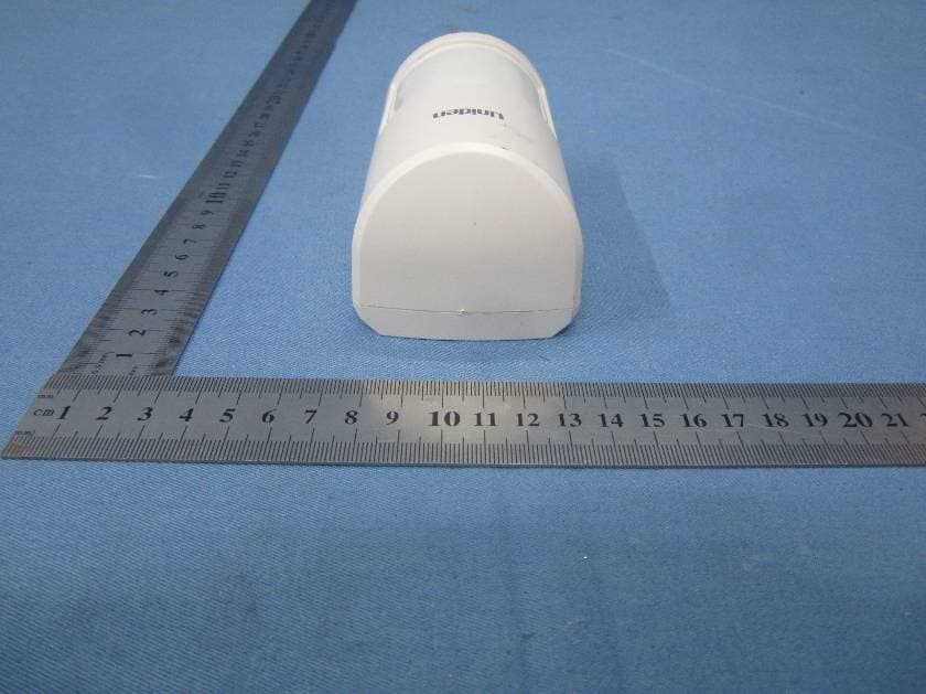
LE2PIR31
Nov 21, 2015Wireless portable / wall-mount area motion alert sensor
Equipment Class
DXX - Part 15 Low Power Communication Device Transmitter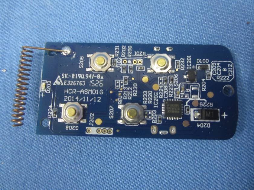
LE2RC41
Nov 21, 2015Wireless multi-functional panic remote controller
Equipment Class
DXX - Part 15 Low Power Communication Device Transmitter
LE2APPCAM25HDA
May 25, 2015720p WIFI Camera
Equipment Class
DTS - Digital Transmission System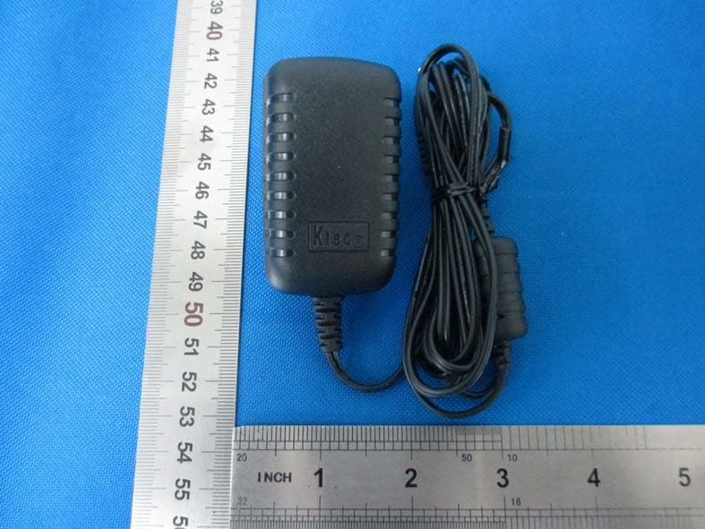
LE2APPCAM24HD
May 24, 2015720p WIFI Camera
Equipment Class
DTS - Digital Transmission System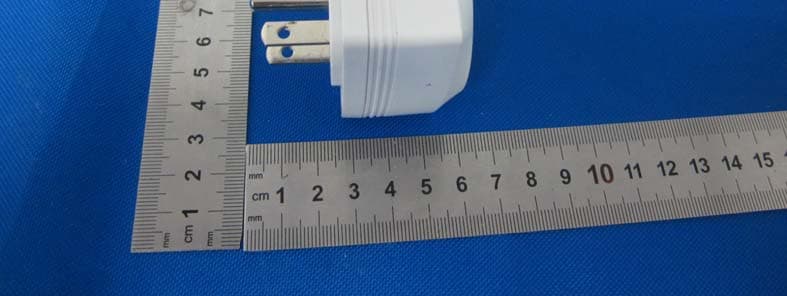
LE2PWR21
Mar 21, 2015Wireless appliance energy management power switch
Equipment Class
DXX - Part 15 Low Power Communication Device Transmitter