LH8RP-S435Automatic Alarm Opening System
Cardin Elettronica spa
Click to zoom
Application Details
- Equipment Class
- CYY - Communications Receiver used w/Pt 15 Transmitter
- Date of Grant
- Dec 10, 2000
- Application Purpose
- Original Equipment
- Date of Application
- Dec 10, 2000
- Equipment Note
- Automatic Alarm Opening System
- Frequency Range
- 433.92000000 - 433.92000000
- Company
- Cardin Elettronica spa
- Country
- Italy
Documents & Files
Document Text
Text extracted from the exhibit documents filed with the FCC. Open a document above to read the original.
Users Manual
ZVL378.00 MOD:20-10-2000 L378.00S43520-10-2000AM CARDIN ELETTRONICA spa Via Raffaello, 36- 31020 San Vendemiano Treviso (TV) Italy Tel:+39/0438.401818 Fax:+39/0438.401831 email (Italy):[email protected] email (Europe):[email protected] Http:www.cardin.it Warning: Changes or alterations made to this device which have not been expressly approved by the party responsible for compliance with the local standards and regulations could cancel the user's authority to operate the equipment. NOTE: This equipment has been tested and found to comply with the limits for a class B digital device, according to part 15 of the FCC rules. These limits are designed to provide reasonable protection against harmful interference to radio communications. However, there is no guarantee that interference will not occur in a particular installation. If this equipment does cause harmful interference to radio or television reception, which can be determined by turning the equipment off and on, the user is advised to try to correct the situation by taking one or more of the following measures: •Reorientate or relocate the receiving antenna •Increase the distance between the equipment and the receiver •Connect the equipment to a wall socket which is on a different ring circuit to that of the receiver •Consult your dealer or an experienced radio/TV technician for help. Description The S435 radio control system consists of one or more transmitters and one or more receivers which can be combined to meet the specific needs of the system. The S435 system uses a highly reliable encoding system guaranteed by the use of dynamic codes. The code is changed for each encoding transmission through the use of an encoding algorithm which only the receiver is able to recognise and therefore decide whether or not the code transmitted corresponds to the original code. The code is generated for each channel in the transmitter using the random arbitrary method with 2 36 combinations. The generated code is memorised in the receiver via radio. The receiver is able to memorise 128 different codes. During the transfer stage the codes are memorised in a non volatile memory module which can be moved to another receiver without having to reprogram it. As this is a system based on dynamic codes each code is processed individually by the receiver. Important This is a device which uses a high security encoding system it follows ther efore that if you lose one or more transmitters you will have to reprogram the system codes. The transmit- ted code changes for each command (rolling code). Disturbance during the transmission will deactivate the relay, at this point the relay can only be activated by first releasing and then pressing the transmitter channel button a second time. Use The S435 radio control allows the remote activation of electrical and electronic appliances with its best use in the following areas: automatic opening systems, alarm systems, and in all systems which require remote control activation (without wires) using secret codes. Transmitter versions TRS435200.0USMiniaturised transmitters2 buttons TRS435400.0USMiniaturised transmitters4 buttons TRS435120.0USMiniaturised transmitters with switch (12 channels)4 buttons TRS43540M.0USWall mounted transmitter4 buttons Receiver versions RCS435128Modular receiver + container4 channels RSS435100Slot-in receiver card1 channel RSS435200Slot-in receiver card2 channels RMS435100.0USMini receiver1 channel RMS435200.0USMini receiver2 channels Memory module This is extractable, furnished with a non volatile EEPROM type memory and contains the system code. The programmed code is maintained in this module even in the absence of power. This component can be ordered as an accessory with s.p.n. code: -YMCC66128 up to 128 codes. Receiver antenna installation Minimum and maximum range of the radio controls. ‘Range’ is intended to mean the working distance, measured in free space, between the receiver and the transmitter with the antenna installed. The range is therefore closely linked to the technical characteristics of the system (power and sensibility) and varies according to the characteristics of the site in which the system is located. It therefore follows that to obtain the best results from the radio control the installation sites for the receiver and the antenna should be carefully chosen. You are not advised to install 2 receivers at a distance of less than 1.5 m from each other and it is also good practise to position the receiver away from computer systems, alarm systems and other possible sources of disturbance. (A bad choice of positioning could compromise the correct performance of the receiver). Antenna The installation of the antenna is fundamental, connected to the receiver it represents the reception point for the radio control. When installing the antenna the following points should be observed: • The receiver is supplied with its own antenna which consists of a piece of rigid wire 170 mm in length. In alternative it is possible to connect an ANS400 tuned antenna using a coaxial cable RG58 (impedance 50 Ω) with a maximum length of 15 m. Outdoor receivers (fig.9) The receiver could be: -in a case fitted with a 14-way terminal board (printed circuit CS926) with the following electrical connections: 12V ac/dc between binding posts 11-12 24V ac/dc between binding posts 10-12 The case type receiver is fitted using "fast-fitting" brackets. The bracket should be fixed to the wall using two raw plugs (check that it is in square). After connecting the wiring the case should be slid onto the bracket therefore fixing it to the wall. If any repair work is necessary the case can be easily extracted by pushing upwards the action of which will separate it from the bracket. Interchangeable channel modules In the receivers the channel functions are printed on the circuit board. The interchangeable channel modules can only have the following configurations and must not be mixed: - from 1 t…
Text truncated - open the document above for the full version.
Block Diagram
LIST OF GENERATED FREQUENCIES Frequencies of the oscillators shown in the block diagrams hereafter: (1)SAW-Resonator Oscillator in the transmitters f =433.92 MHz. (2)SAW-Local Oscillator in the receiversf LO = 433.42 MHz. (3)Processor Oscillator in the MINI Receiverf =5 MHz. (4)Processor Oscillator in the radio programmer f =10 MHz. P. 1 of 4 CARDIN ELETTRONICA S.p.A. R.& D. Dept. P. 2 of 4 SERIES S435 - 2 CH TRANSMITTER SCHEMATIC BLOCK SECURITY CODE EEPROM uPROCESSOR SAW-RESONATOR OSCILLATOR (1) ANTENNA+ RF FILTER BATTERY 2 CHANNEL BUTTONS CODE GENERATION BUTTON SERIES S435 - 4 CH TRANSMITTER SCHEMATIC BLOCK SECURITY CODE EEPROM uPROCESSOR SAW-RESONATOR OSCILLATOR (1) ANTENNA+ RF FILTER BATTERY 4 CHANNEL BUTTONS CODE GENERATION BUTTON SERIES S435 - 12 CH TRANSMITTER SCHEMATIC BLOCK SECURITY CODE EEPROM uPROCESSOR SAW-RESONATOR OSCILLATOR (1) ANTENNA+ RF FILTER BATTERY 4 CHANNEL BUTTONS 1ST, 2ND, 3RD CHANNEL BANK SELECTOR CODE GENERATION BUTTON CARDIN ELETTRONICA S.p.A. R.& D. Dept. P. 3 of 4 SERIES S435 - MINI RECEIVER SCHEMATIC BLOCK POWER SUPPLY ANTENNA+ RF FILTER RF INPUT AMPLIFIER DEMODULATORuPROCESSOR uP OSCILLATOR (3) SECURIY CODE EEPROM CARD POWER ON RESET CIRCUIT 2 RELAYS SAW LOCAL OSCILLATOR (2) TERMINAL BOARDS MEMO BUTTON DELETE BUTTON JUMPERS FOR CHANNEL SELECTION CARDIN ELETTRONICA S.p.A. R.& D. Dept. P. 4 of 4 SERIES S435 -RADIOPROGRAMMER SCHEMATIC BLOCK POWER SUPPLY ANTENNARF MODULE (2)uPROCESSOR uP OSCILLATOR (4) SECURIY CODE EEPROM CARD POWER ON RESET CIRCUIT 3 RELAYS FOR MOTOR CONTROL I/O CONNECTOR MEMO & DELETE BUTTONS WORK CYCLE SETTING DIP-SWITCH FOR CHANNEL SELECTION DYNAMIC BUTTON open-stop-close-stop
Cover Letter(s)
ESR-BriefCert-00-06-04 E LECTRO M AGNETIC C OMPATIBILITY C ERTIFICATION EMCCert DR. RAŠEK · Boelwiese 5 · 91320 Ebermannstadt · Germany Zertifizierungsinstitut · Certification Institute Sachverständigenbüro · Technical Experts Von der Industrie- und Handelskammer für Ober- franken Bayreuth 1977 öffentlich bestellter und ver- eidigter Sachverständiger für elektrische Störungen und elektromagnetische Verträglichkeit BENANNTE STELLE / NOTIFIED BODY 89/336, 91/263, 93/97, 98/13, 99/5/EC BRD/RegTP EU # 0678 ZUSTÄNDIGE STELLE / COMPETENT BODY 89/336/EEC BAPT # BPT-ZE-009/94 Telefon:0 91 94 - 93 31 International:+ 49 - 91 94 - 93 31 Telefax:0 91 94 - 79 64 - 84 International:+ 49 - 91 94 - 79 64 - 84 Mail:[email protected] Web:http : //www . emcc . de Ihr ZeichenUnser ZeichenDatum Your ReferenceOur ReferenceDate V.A.T. Id. Nr.: DE 1326 389 00 Bank: HypoVereinsbank Forchheim, Germany # 1040293139 (BLZ 760 202 14), S.W .I.F.T.-Code HYVE DE MM 222 Sparkasse Forchheim, Germany # 74468 (BLZ 763 510 40), S.W .I.F.T.-Code BYLA DE MM Citibank New York, USA # 50273189, S.W .I.F.T.-Code 021000089 S INCE 1977 Application for Certification on behalf of Cardin Elettronica S.p.A. Confidentiality / FCC ID: LH8RP-S435 Dear Sir/Madam Pursuant to Section 0.459 of the Commission's rules (CFR 47), we request confidentiality for portions of the material contained in the application for FCC ID: LH8RP-S435 and that the identified material be withheld from public inspection following the grant of this authorization. This material contains Cardin's trade secrets and confidential information that Cardin Elettronica S.p.A. does not customarily release to the public and which is otherwise not generally available to the public. Confidentiality is requested for the following exhibits: 1. WIRING DIAGRAM 2. PARTS LIST Yours sincerely, EMCCert DR. RAŠEK Klaus Knörig Agent for Cardin Elettronica S.p.A. EMCC Dr. Rasek Boelwiese 5 Ebermannstadt, Germany 91320 Federal Communications Commission Authorizations and Evaluation Division 7435 Oakland Mills Road Columbia Maryland 21046 USA Kn/-950295AOB/nb2000-11-27
External Photos
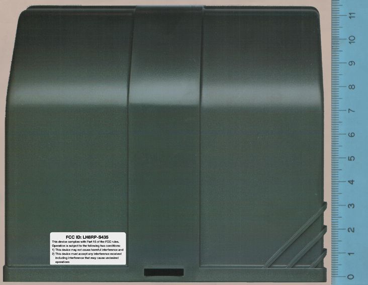
FCC ID: LH8RP-S435 RADIO LABORATORIES EMC LABORATORIES TTI-P-G 094/94 TTI-P-G 074/95 EMCC DR. RAäEK Moggast 72-74 91320 Ebermannstadt Germany FCC Registration # 90566 RPS_Annex2e.doc Telephone: +49-9194-9016 Telefax:+49-9194-8125 Mail:[email protected] Web:http://www.emcc.de Page 1 of 3 ANNEX 2 TO TEST REPORT # EMCC-950295AOB, 2000-NOV-21 PHOTOGRAPHS OF EQUIPMENT UNDER TEST (EUT) EXTERNAL VIEWS EQUIPMENT UNDER TEST: Trade Name:S435 Model:RPS435000.0US Serial No:None Equipment Category:Receiver Manufacturer:CARDIN ELETTRONICA SPA Address:Via Raffaello 36 31020 S. Vendemiano (TV) Italy Phone:+39-0438-401818 Fax:+39-0438-401831 RELEVANT STANDARD:47 CFR Part 15B - Unintentional Radiators CONTENTS Page 1 FRONT VIEW OF EUT, ANTENNA ATTACHED..................................................................................................... 2 2 REAR VIEW OF EUT ............................................................................................................................................... 3 FCC ID: LH8RP-S435 Annex 2 to Test Report #EMCC-950295AOB Page 2 of 3 Issue Date: 2000-NOV-21 TEST OF CARDIN ELETTRONICA SPA S435 MODEL RPS435000.0US TO 47 CFR PART 15B - UNINTENTIONAL RADIATORS RPS_ANNEX2E.DOC 1 FRONT VIEW OF EUT, ANTENNA ATTACHED FCC ID: LH8RP-S435 Annex 2 to Test Report #EMCC-950295AOB Page 3 of 3 Issue Date: 2000-NOV-21 TEST OF CARDIN ELETTRONICA SPA S435 MODEL RPS435000.0US TO 47 CFR PART 15B - UNINTENTIONAL RADIATORS RPS_ANNEX2E.DOC 2 REAR VIEW OF EUT
ID Label/Location Info
FCC ID: LH8RP-S435 This device complies with Part 15 of the FCC rules. Operation is subject to the following two conditions: 1) This device may not cause harmful interference and 2) This device must accept any interference received including interference that may cause undesired operations ETICHETTE conformità LH8RP-S435 S435 RXPR 20-11-2000 ZVE394 S435 RXPR CONFORMITÀ USA (RPS435000) SCALA: 1:1 Description : Product Code : Date : Drawing number : P.J.Heath CARDIN ELETTRONICA S.p.A - 31020 San Vendemiano (TV) Italy - via Raffaello, 36 Tel: 0438/401818 Fax: 0438/401831 Draft : All rights reserved. Unauthorised copying or use of the information contained in this document is punishable by law Materiale: PVC Grey Fondo/Scrittura: Nero Bordo: Nessuno
Internal Photos
FCC ID: LH8RP-S435 RADIO LABORATORIES EMC LABORATORIES TTI-P-G 094/94 TTI-P-G 074/95 EMCC DR. RAäEK Moggast 72-74 91320 Ebermannstadt Germany FCC Registration # 90566 RPS_Annex2i.doc Telephone: +49-9194-9016 Telefax:+49-9194-8125 Mail:[email protected] Web:http://www.emcc.de Page 1 of 5 ANNEX 2 TO TEST REPORT # EMCC-950295AOB, 2000-NOV-21 PHOTOGRAPHS OF EQUIPMENT UNDER TEST (EUT) INTERNAL VIEWS EQUIPMENT UNDER TEST: Trade Name:S435 Model:RPS435000.0US Serial No:None Equipment Category:Receiver Manufacturer:CARDIN ELETTRONICA SPA Address:Via Raffaello 36 31020 S. Vendemiano (TV) Italy Phone:+39-0438-401818 Fax:+39-0438-401831 RELEVANT STANDARD:47 CFR Part 15B - Unintentional Radiators CONTENTS Page 1 COVER OPENED, PRINT CIRCUIT BOARD, SIDE 1 ............................................................................................. 2 2 PRINT CIRCUIT BOARD, SIDE 1 ............................................................................................................................ 3 3 PRINT CIRCUIT BOARD, SIDE 2 ............................................................................................................................ 4 4 PRINT CIRCUIT BOARD, SIDE VIEW, RECEIVER INPUT STAGE ....................................................................... 5 FCC ID: LH8RP-S435 Annex 2 to Test Report #EMCC-950295AOB Page 2 of 5 Issue Date: 2000-NOV-21 TEST OF CARDIN ELETTRONICA SPA S435 MODEL RPS435000.0US TO 47 CFR PART 15B - UNINTENTIONAL RADIATORS RPS_ANNEX2I.DOC 1 COVER OPENED, PRINT CIRCUIT BOARD, SIDE 1 FCC ID: LH8RP-S435 Annex 2 to Test Report #EMCC-950295AOB Page 3 of 5 Issue Date: 2000-NOV-21 TEST OF CARDIN ELETTRONICA SPA S435 MODEL RPS435000.0US TO 47 CFR PART 15B - UNINTENTIONAL RADIATORS RPS_ANNEX2I.DOC 2 PRINT CIRCUIT BOARD, SIDE 1 FCC ID: LH8RP-S435 Annex 2 to Test Report #EMCC-950295AOB Page 4 of 5 Issue Date: 2000-NOV-21 TEST OF CARDIN ELETTRONICA SPA S435 MODEL RPS435000.0US TO 47 CFR PART 15B - UNINTENTIONAL RADIATORS RPS_ANNEX2I.DOC 3 PRINT CIRCUIT BOARD, SIDE 2 FCC ID: LH8RP-S435 Annex 2 to Test Report #EMCC-950295AOB Page 5 of 5 Issue Date: 2000-NOV-21 TEST OF CARDIN ELETTRONICA SPA S435 MODEL RPS435000.0US TO 47 CFR PART 15B - UNINTENTIONAL RADIATORS RPS_ANNEX2I.DOC 4 PRINT CIRCUIT BOARD, SIDE VIEW, RECEIVER INPUT STAGE
Operational Description
CARDIN ELETTRONICA S.p.A. R.& D. Dept. P. 1 of 4 1.0 INTRODUCTION Manufacturer’s data CARDIN ELETTRONICA SPA VIA RAFFAELLO 36 Tel. +39-0438-401818 31020 S. VENDEMIANO (TV) Fax.+39-0438-401831 ITALY Product marketing and commercial name S435 RADIO CONTROL (operating frequency: 433.92 MHz) consists of the following equipments: - miniaturized transmitter 2 channels (TX2) TRS435 200.0US - miniaturized transmitter 4 channels (TX4) TRS435 400.0US - wall mounted transmitter 4 channels (TX4M) TRS435 40M.0US - miniaturized transmitter 12 channels (TX12) TRS435 120.0US Note: the transmitter versions only differ from one and other by the number of functions (channels) which they are able to activate from a distance. The various containers differ from one and other by the number of buttons which depend on the model; it’s necessary remember that the four and twelve-channel transmitters use the same box but the twelve-channel transmitters has a selector to address the first, the second and the third channel bank. By looking at the wiring diagram it can be seen that all the transmitters feature the same radio frequency section and that only the encode section differs, due to the number of channel functions. - two-channel mini receiver (RXM2CH) RMS435 200.0US - one-channel mini receiver (RXM1CH) RMS435 100.0US - 120V radio programmer (RXPR) RPS435 000.0US Note1: the RF part in the 120V radio programmer is represented by the YRFIBR-433 module. Technical report drawn up by: Ing. M. Terruso Resp. Certif. & Omologhe – Cardin Elettronica S.p.A. CARDIN ELETTRONICA S.p.A. R.& D. Dept. P. 2 of 4 2.0 GENERAL DESCRIPTION - Radio control system model S435 consisting of one or more transmitters and one or more receivers; - Carrier frequency in the UHF waveband controlled by a SAW RESONATOR; - PCM type encoding signal transmitted in modulation bandwidth ASK; - Superetherodyne receiver, single conversion with local oscillator SAW, low rumor RF preamplifier and integrated RF-IF section; - Encoding and decoding device using a highly reliable 49 bit custom LSI, code transmission with complementary parity, automatic pre-chosen channel selection; - Highly reliable encoding system guaranteed by the use of dynamic codes. The code is changed for each encoding transmission through the use of an encoding algorithm which only the receiver is able to recognize and therefore decide whether or not the code transmitted corresponds to the original code. The code is generated for each channel in the transmitter using the random arbitrary method with 2 36 combinations. The generated code is memorized in the receiver via radio. The receiver is able to memorize 32 or 128 or 512 different codes. 2.1 USE AND APPLICATIONS The Radio control model S435 permits the remote activation of electrical and electronic appliances and has its best use in the following areas: • Automatic opening systems • Alarm systems and in all systems which require remote activation (without wires) using secret user codes in compliance with the local safety standards in force. CARDIN ELETTRONICA S.p.A. R.& D. Dept. P. 3 of 4 3.0 PRODUCT DESCRIPTION • 120V radioprogrammer (with container) - External casing in ABS (overall dimensions 115 x 139 x 44mm) - Electronic circuit with the slot-in receiver card YRFIBR-433 and motor control in output - Power supply: 110-120 V ac PRODUCT DESCRIPTION CODE Radioprogrammer RPS435 000.0US • RF module YRFIBR_433 - Only radio frequency part - Band width in Low frequency 2400 Hz. - Slot-in receiver decoded outputs with logical level 5V. CMOS - Circuit board dimensions 50 x 20 mm - Electronic p.c.b. card with an 8-way pin connector to be inserted in to devices suited to its application - Power supply: 5 V. dc PRODUCT DESCRIPTION CODE RF module YRFIBR-433 YRF433IBR0CE • Mini receiver (with container) - One and two channel mini receivers (external dimensions 20x60x90 mm.) - For internal use the device features an easily accessible terminal block and - channel selection on the card - Power supply: 12-24V ac/dc - Up to 32 codes PRODUCT DESCRIPTION CODE 2 channel mini receiver RMS435 200.0US 1 channel mini receiver RMS435 100.0US CARDIN ELETTRONICA S.p.A. R.& D. Dept. P. 4 of 4 • Miniaturized transmitters - Shock-proof container - Overall dimensions 80 x 39 x 12 mm - Led indicating signal emission - Access door permitting battery replacement and user code programming - Power supply: pencil battery 12V (model GP23A) - Versions with up to 12 channels - 2 36 random code combinations with dynamic code transmission PRODUCT DESCRIPTION CODE Miniaturized 2-channel transmitter TRS435 200.0US Miniaturized 4-channel transmitter TRS435 400.0US Wall mounted transmitter 4-channel TRS435 40M.0US Miniaturized 12-channel transmitter TRS435 120.0US
Test Report
FCC ID: LH8RP-S435 Test Report #EMCC-950295AOB Page 2 of 12 Issue Date: 2000-NOV-21 TEST OF CARDIN ELETTRONICA SPA S435 MODEL RPS435000.0US TO 47 CFR PART 15B - UNINTENTIONAL RADIATORS FCC_RPS435.DOC CONTENTSPage 1 GENERAL INFORMATION ..................................................................................................................................................................... 3 1.1 Purpose........................................................................................................................................................................................ 3 1.2 Limits and Reservations............................................................................................................................................................. 3 1.3 Test Location ............................................................................................................................................................................... 3 1.4 Manufacturer ............................................................................................................................................................................... 3 1.5 Dates ............................................................................................................................................................................................ 3 2 PRODUCT DESCRIPTION...................................................................................................................................................................... 4 2.1 Equipment Under Test (EUT) ..................................................................................................................................................... 4 2.2 Configuration and Peripherals of EUT ...................................................................................................................................... 4 2.3 Mode of Operation During Testing ............................................................................................................................................ 4 2.4 Modifications Required for Compliance.................................................................................................................................... 4 3 TEST RESULTS SUMMARY .................................................................................................................................................................. 5 4 CONDUCTED EMISSIONS TESTS ........................................................................................................................................................ 6 4.1 Regulation.................................................................................................................................................................................... 6 4.2 Test Equipment ........................................................................................................................................................................... 6 4.3 Test Procedures .......................................................................................................................................................................... 6 4.4 Test Results ................................................................................................................................................................................. 7 5 RADIATED EMISSIONS TEST ............................................................................................................................................................... 8 5.1 Regulation.................................................................................................................................................................................... 8 5.2 Test Equipment ........................................................................................................................................................................... 9 5.3 Test Procedures ........................................................................................................................................................................ 10 5.4 Field Strength Calculation........................................................................................................................................................ 10 5.5 Test Results ............................................................................................................................................................................... 11 6 MISCELLANEOUS COMMENTS AND NOTES .................................................................................................................................... 12 7 LIST OF ANNEXES............................................................................................................................................................................... 12 FCC ID: LH8RP-S435 Test Report #EMCC-950295AOB Page 3 of 12 Issue Date: 2000-NOV-21 TEST OF CARDIN ELETTRONICA SPA S435 MODEL RPS435000.0US TO 47 CFR PART 15B - UNINTENTIONAL RADIATORS FCC_RPS435.DOC 1 GENERAL INFORMATION 1.1 Purpose The purpose of this report is to show compliance to the FCC regulations for unintentional radiators operating under section 15.101 ff. of the Code of Federal Regulations title 47. 1.2 Limits and Reservations The test results in this report apply only to the particular Equipment Under Test (EUT) as declared in this report. This test report shall not be reproduced except in full without the written permission of EMCC DR. RAäEK. 1.3 Test Location Company Name:EMCC DR. RAäEK Street:Moggast 72-74 City:91320 Ebermannstadt Country:Germany Laboratory:Test Laboratory of EMCC DR. RAäEK FCC Registration Number: 90566 This site has been fully described in a report submitted to the FCC, and accepted in the letter dated February 09, 2000 Registration Number 90566. Phone:+49-9194-9016 Fax:+49-9194-8125 E-Mail:emc…
Text truncated - open the document above for the full version.
Test Setup Photos
FCC ID: LH8RP-S435 RADIO LABORATORIES EMC LABORATORIES TTI-P-G 094/94 TTI-P-G 074/95 EMCC DR. RAäEK Moggast 72-74 91320 Ebermannstadt Germany FCC Registration # 90566 RPS_Annex1.doc Telephone: +49-9194-9016 Telefax:+49-9194-8125 Mail:[email protected] Web:http://www.emcc.de Page 1 of 3 ANNEX 1 TO TEST REPORT # EMCC-950295AOB, 2000-NOV-21 PHOTOGRAPHS OF TEST SETUPS EQUIPMENT UNDER TEST: Trade Name:S435 Model:RPS435000.0US Serial No:None Equipment Category:Receiver Manufacturer:CARDIN ELETTRONICA SPA Address:Via Raffaello 36 31020 S. Vendemiano (TV) Italy Phone:+39-0438-401818 Fax:+39-0438-401831 RELEVANT STANDARD:47 CFR Part 15B - Unintentional Radiators CONTENTS Page 1 CONDUCTED EMISSIONS TEST............................................................................................................................ 2 1.1 Photograph: EUT on non conductive table ..................................................................................................... 2 2 RADIATED EMISSIONS TEST ................................................................................................................................ 3 2.1 Photograph: EUT on non conductive table ..................................................................................................... 3 FCC ID: LH8RP-S435 Annex 1 to Test Report #EMCC-950295AOB Page 2 of 3 Issue Date: 2000-NOV-21 TEST OF CARDIN ELETTRONICA SPA S435 MODEL RPS435000.0US TO 47 CFR PART 15B - UNINTENTIONAL RADIATORS RPS_ANNEX1.DOC 1 CONDUCTED EMISSIONS TEST 1.1 Photograph: EUT on non conductive table FCC ID: LH8RP-S435 Annex 1 to Test Report #EMCC-950295AOB Page 3 of 3 Issue Date: 2000-NOV-21 TEST OF CARDIN ELETTRONICA SPA S435 MODEL RPS435000.0US TO 47 CFR PART 15B - UNINTENTIONAL RADIATORS RPS_ANNEX1.DOC 2 RADIATED EMISSIONS TEST 2.1 Photograph: EUT on non conductive table
Contact Information
Applicant
Alessandro Fiorotto(Administrator)
Technical Contact
Cardin ElettronicaMaurizio Terruso
[email protected]+39-438-401818
Via Raffaello 36 · San Vendemiano (TV) · Italy
Non-Technical Contact
Cardin ElettronicaMaurizio Terruso
[email protected]+39-438-401818
Test Firm
EMCCons Dr. Rasek GmbH & Co. KGWinfried hoffmann
Technical Specifications
| # | Rule Parts | Frequency Range | Power Output |
|---|---|---|---|
| 1 | 15B | 433.92 MHz - 433.92 MHz | - |
Other Applications from Cardin Elettronica spa

LH8T-S435
Dec 14, 2000Automatic alarm opening system
Equipment Class
DSC - Part 15 Security/Remote Control Transmitter
LH8RM-S435
Dec 07, 2000Automatic alarm opening system
Equipment Class
CYY - Communications Receiver used w/Pt 15 Transmitter
LH8R-XRADO
Sep 29, 1998CYY - Communications Receiver used w/Pt 15 Transmitter
Equipment Class
CYY - Communications Receiver used w/Pt 15 Transmitter
LH8T-XRADO
Sep 29, 1998DSC - Part 15 Security/Remote Control Transmitter
Equipment Class
DSC - Part 15 Security/Remote Control TransmitterLH8S306R1
Apr 04, 1994Remote Control Receiver
Equipment Class
CRR - Superregenerative Receiver