LHJ-FANModule with Multi-Band LTE and WCDMA
Continental Automotive Systems, Inc.
Click to zoom
Application Details
- Equipment Class
- PCB - PCS Licensed Transmitter
- Date of Grant
- Sep 30, 2015
- Application Purpose
- Original Equipment
- Date of Application
- Sep 30, 2015
- Equipment Note
- Module with Multi-Band LTE and WCDMA
- Frequency Range
- 1852.40000000 - 1907.60000000
- Country
- United States
Documents & Files
Document Text
Text extracted from the exhibit documents filed with the FCC. Open a document above to read the original.
Users Manual
OEM Integration Manual for FAN (FCC ID: LHJ-FAN, IC: 2807E-FAN) Integration Guide for FAN Module 1. Product Overview FAN 4G/3G module is a proprietary modem designed and manufactured by Continental Automotive Systems, Inc. The modem will be integrated into a telematics control unit (TCU), designed and developed by Continental Automotive, Inc. The TCU will be installed into consumer vehicles during the vehicle OEM’s factory assembly process. Primary use-cases are data-centric with data and voice connections to Telematics Service Providers (TSP). Figure 1. Top view of FAN module. Figure 2. Bottom view of FAN module. FAN Feature Table: Feature Description Operating Bands LTE FDD: 17, 4, 2, and 5 WCDMA: II and V Application Interface USB 4 wire UART 2 wire UART Audio: PCM ACC_POWER_ON pin Hardware Reset Pin BOOT_OK status pin MSG indicator pin JTAG Antenna interface (Primary, MIMO) Data Services LTE: data rates 100MBps DL / 50Mbps UL OEM Integration Manual for FAN (FCC ID: LHJ-FAN, IC: 2807E-FAN) 2. Regulatory Compliance Note FCC: This device complies with Part 2, Part 22(H), Part 24(E) and Part 27 of the FCC Rules. The FCC ID for this device is LHJ-FAN. Operation is subject to the following two conditions: 1. This device may not cause harmful interference. 2. This device must accept any interference received, including interference that may cause undesired operation. Industry of Canada: This device complies with Industry Canada’s license-exempt RSSs. Operation is subject to the following two conditions: (1) This device may not cause interference; and (2) This device must accept any interference, including interference that may cause undesired operation of the device.” « Le présent appareil est conforme aux CNR d'Industrie Canada applicables aux appareils radio exempts de licence. L'exploitation est autorisée aux deux conditions suivantes : (1) l'appareil ne doit pas produire de brouillage, et (2) l'utilisateur de l'appareil doit accepter tout brouillage radioélectrique subi, même si le brouillage est susceptible d'en compromettre le fonctionnement. » This radio transmitter (2807E-FAN) has been approved by Industry Canada to operate with the antenna types listed below with the maximum permissible gain indicated. Antenna types not included in this list, having a gain greater than the maximum gain indicated for that type, are strictly prohibited for use with this device. « Le présent émetteur radio (2807E-FAN) a été approuvé par Industrie Canada pour fonctionner avec les types d'antenne énumérés ci-dessous et ayant un gain admissible maximal. Les types d'antenne non inclus dans cette liste, et dont le gain est supérieur au gain maximal indiqué, sont strictement interdits pour l'exploitation de l'émetteur.» 3. Device Installation and User Manual The FAN module is a proprietary product designed and manufactured by Continental Automotive Systems, Inc. for integration into telematics control units manufactured by Continental Automotive Systems, Inc. for automotive OEMs. i. The module is limited to installation ONLY in an integrated device manufactured by Continental Automotive Systems, Inc. ii. During manufacturing process of the integrated device, the module is soldered onto the pcb of the integrated device. iii. The integrated device must provide RF connectors to external antennas. The typical reference design for the trace layout, including pcb stack-up and trace length is shown below: OEM Integration Manual for FAN (FCC ID: LHJ-FAN, IC: 2807E-FAN) Typical RF trace layout between the FAN module and RF Connector: Recommended RF Connector Type: Fakra X203 is the recommended connector location for MIMO1 (primary antenna) connector. Recommended RF trace length is less than 40 mm. X202 is the recommended connector location for MIMO2 (diversity antenna) connector. Recommended RF trace length is less than 45 mm. OEM Integration Manual for FAN (FCC ID: LHJ-FAN, IC: 2807E-FAN) PCB Material: FR 4 PCB design information: Microstrip on layer 1 with ground on layer 2 / 50 ohm Single Ended Line/ 840 μm W 840 μm S Stripline on layer 2 with ground on layers 1&3 / 50 Ohm Single Ended Line/ 405 μm W iv. Automotive OEM is responsible for ensuring that the end-user has no manual instructions to remove or install module. v. The module is limited to installation in mobile applications, according to Part 2.1091(b). vi. No other operation configurations are allowed. vii. Changes or modifications to this system by other than a facility authorized by Continental could void authorization to use this equipment. viii. The module must be installed to provide a separation distance of at least 20 cm from all persons and must not be co-located or operate in conjunction with any other antenna or transmitter. ix. The integrator is responsible for fulfilling FCC and IC requirements for the integrated device. If Continental chooses to re-use modular approval, then the TCU shall be clearly labeled with an external label containing the integrated modem’s FCC ID. For example, the label can include text “Contains device with FCC ID: LHJ-FAN and IC: 2807E-FAN”. OEM Integration Manual for FAN (FCC ID: LHJ-FAN, IC: 2807E-FAN) Antenna requirements for use with FAN module: • The module must be installed to provide a separation distance of at least 20cm from all persons and must not be co-located or operating in conjunction with any other antenna or transmitter. • The FAN module is for use with external antennas ONLY. • For all operating bands the maximum antenna gain is 6 dBi including cable loss. • The maximum gain of the antenna path (cable loss + antenna gain) shall not exceed the above mentioned values. This radio transmitter (FCC ID: LHJ-FAN; IC: 2807E-FAN) has been approved by FCC and Industry Canada to operate with the antenna types listed below with the maximum permissible gain indicated. Antenna types not included in this list, having a gain greater than the maximum gain indicated for that type, are strictly prohibited for use wit…
Text truncated - open the document above for the full version.
Cover Letter(s)
1(1) Date: September 17 th , 2015 Application Examiner Subject: Continental Automotive Systems, Inc. FCC ID: LHJ-FAN Original submission To whom it may concern, Permanent Confidentiality Request is hereby submitted by Continental Automotive Systems, Inc to withhold permanently from public review certain portions of the application FCC certification for the referenced FCC identifier. This request for confidentiality is made pursuant to 47 CFR 0.457(d) and 0.459 of the FCC Rules. In particular, the following sections of the application are to be kept permanently confidential: Schematics Part placement information Block diagrams Parts list Operational Description Tune-up procedure Rationale for request for confidentiality: Continental Automotive Systems, Inc. has invested considerable time and materials in research and development to produce the referenced product. Disclosure of the permanently confidential portions of this application to competitors would not only give them significant competitive advantages in developing similar products, but would also disclose successful implementation of unpublished, leading edge technology developed by us. Disclosure of the short-term confidential portions of this application during the period of importation and/or distribution would reveal key aspects of proprietary technology to competitors and diminish the value of our investment in research and development. The fee for confidentiality has been submitted along with the fee for certification. If you have questions or need further information, please contact the undersigned. Sincerely, Name: Jeremy Pickens Title: Senior Engineer / Agent for Continental Automotive Systems, Inc. Date: 17 September 2015
Cover Letter(s)
Attention: Application Examiner RE: Request for Single-Modular Transmitter Approval for FCC ID: LHJ-FAN Applicant: Continental Automotive Systems, Inc. FCC ID: LHJ-FAN To whom it may concern, Limited Single-Modular Transmitter This letter is to declare that the module with FCC ID LHJ-FAN partially meets the definition of Single Modular Transmitter Subject to Section 15.212 Rules as described by the check-list below: i. The radio frequency circuitry is shielded. All other physical components are also covered by shield. ii. The module has buffered USB and UART data inputs/outputs to insure that the device will comply with Part 15 requirements. iii. The module contains on-board power supply regulator. iv. A permanently attached antenna or unique antenna connector is not a requirement for licensed modules. v. The module demonstrated compliance in a stand-alone configuration. vi. The module has a permanently affixed external label containing FCC ID information. vii. The module is compliant with FCC Part 22H, 24E and 27 in a stand-alone configuration. viii. The module is compliant with RF exposure requirements. Based on this information LHJ-FAN meets seven of eight criteria for single-modular transmitter. Continental would like to seek a Limited Single-Modular Approval for the module. Should you have any questions, please feel free to contact the undersigned. Sincerely, Jeremy Pickens SGS North America Agent for Continental Automotive Systems, Inc.
ID Label/Location Info
1. Label ( Size : 29*25 mm ) Continental FAN Product Label LGI WDLT-AT101-FCERT MODEL : FANFCC ID : LHJ-FANIC: 2807E-FANDATE CODE : 5127FW Ver. : 05.49RConti P/N : A2C01934400Decimal IMEI358885060000001SERIAL NO : CB0753151000000
Internal Photos
FCC ID : LHJ-FAN IC: 2807E-FAN FAN top view without shield and frame FAN bottom view
RF Exposure Info
Test Report Number: 3807621EMC03 Rev: 2 Continental Automotive Systems, Inc. / FAN Page: 1 of 5 Remarks: This report details the results of the testing carried out on one sample, the results contained in this test report do not relate to other samples of the same product. The manufacturer should ensure that all products in series production are in conformity with the product sample detailed in this report. This report may only be reproduced and distributed in full. If the product in this report is used in any configuration other than that detailed in the report, the manufacturer must ensure the new system complies with all relevant standards. Any mention of SGS International Electrical Approvals or Testing done by SGS International Electrical Approvals in connection with distribution or use of the product described in this report must be approved by SGS international Electrical Approvals in writing. RF Exposure Report Project Number: 3807621 Report Number: 3807621EMC03 Revision Level: 2 Client: Continental Automotive Systems, Inc. Equipment Under Test: Wireless Modem Module Model Name: FAN Applicable Standards: Part 2, Part 22(H), Part 24(E) RSS-102, Issue 5 RSS-130, Issue 1 RSS-132, Issue 3 RSS-133, Issue 6 RSS-139, Issue 3 Report issued on: 25 September 2015 Test Result: Compliant Tested by: Jeremy O. Pickens, Senior EMC Engineer Reviewed by: David Schramm, EMC/RF/SAR/HAC Manager Test Report Number: 3807621EMC03 Rev: 2 Continental Automotive Systems, Inc. / FAN Page: 2 of 5 SGS North America Inc. Consumer Testing Services 620 Old Peachtree Road NW, Suite 100, Suwanee, GA 30024 t (770) 570-1800 www.us.sgs.com/cts Member of the SGS Group (SGS SA TABLE OF CONTENTS 1 SUMMARY OF TEST RESULTS ..................................................................................................................................... 3 1.1 MODIFICATIONS REQUIRED TO COMPLIANCE ................................................................................................................ 3 2 GENERAL INFORMATION ............................................................................................................................................. 3 2.1 CLIENT INFORMATION ................................................................................................................................................... 3 2.2 TEST LABORATORY ....................................................................................................................................................... 3 2.3 GENERAL INFORMATION OF EUT .................................................................................................................................. 3 2.4 OPERATING MODES AND CONDITIONS .......................................................................................................................... 3 3 RF EXPOSURE ................................................................................................................................................................... 4 3.1 TEST RESULT ................................................................................................................................................................. 4 3.2 TEST METHOD ............................................................................................................................................................... 4 3.3 TEST SITE ...................................................................................................................................................................... 4 3.4 TEST EQUIPMENT .......................................................................................................................................................... 4 3.5 TEST DATA .................................................................................................................................................................... 4 4 REVISION HISTORY ........................................................................................................................................................ 5 Test Report Number: 3807621EMC03 Rev: 2 Continental Automotive Systems, Inc. / FAN Page: 3 of 5 SGS North America Inc. Consumer Testing Services 620 Old Peachtree Road NW, Suite 100, Suwanee, GA 30024 t (770) 570-1800 www.us.sgs.com/cts Member of the SGS Group (SGS SA 1 Summary of Test Results Basic Standards Test Result Radiated Power: ERP FCC Part 1.1310 RSS-102 Reported 1.1 Modifications Required to Compliance None 2 General Information 2.1 Client Information Name: Continental Automotive System, Inc.. Address: 21440 West Lake Cook Road City, State, Zip, Country: Deer Park, IL 60010, USA 2.2 Test Laboratory Name: SGS North America, Inc. Address: 620 Old Peachtree Road NW, Suite 100 City, State, Zip, Country: Suwanee, GA 30024, USA 2.3 General Information of EUT Type of Product: Wireless Modem Module Model Number: FAN FCC ID: LHJ-FAN IC ID: 2807E-FAN S/N: CJ0825157000345 IMEI Number: 352598070013450 Rated Voltage: 10.2 - 13.8 Vdc, Test Voltage: 12 Vdc Tx Frequency Range: 826.4– 846.6 MHz (WCDMA Band V) 1852.4– 1907.6 MHz (WCDMA Band II) 1850 - 1910 MHz (LTE Band 2) 1710 – 1755 MHz (LTE Band 4) 824 – 849 MHz (LTE Band 5) 704 – 716 MHz (LTE Band 17) FCC Classification: PCS Licensed Transmitter PCB Type: Pre Production Sample Received Date: 28 July 2015 Dates of testing: 17 Aug - 31 Aug 2015 2.4 Operating Modes and Conditions For this assessment, the EUT’s maximum power including the maximum tolerance was considered. Test Report Number: 3807621EMC03 Rev: 2 Continental Automotive Systems, Inc. / FAN Page: 4 of 5 SGS North America Inc. Consumer Testing Services 620 Old Peachtree Road NW, Suite 100, Suwanee, GA 30024 t (770) 570-1800 www.us.sgs.com/cts Member of the SGS Group (SGS SA 3 RF Exposure 3.1 Test Result Test Description Product Specific Standard Test Result RF Exposure FCC Part 1.1310 RSS-102 Compliant 3.2 Test Method Using the maximum power (including tune-up tol…
Text truncated - open the document above for the full version.
Test Report
Test Report Number: 3807621EMC01 Rev: 2 Continental Automotive Systems, Inc. / FAN Page: 1 of 81 Remarks: This report details the results of the testing carried out on one sample, the results contained in this test report do not relate to other samples of the same product. The manufacturer should ensure that all products in series production are in conformity with the product sample detailed in this report. This report may only be reproduced and distributed in full. If the product in this report is used in any configuration other than that detailed in the report, the manufacturer must ensure the new system complies with all relevant standards. Any mention of SGS International Electrical Approvals or Testing done by SGS International Electrical Approvals in connection with distribution or use of the product described in this report must be approved by SGS international Electrical Approvals in writing. EMC Test Report Project Number: 3807621 Report Number: 3807621EMC01 Revision Level: 2 Client: Continental Automotive Systems, Inc. Equipment Under Test: Wireless Modem Module Model: FAN FCC Rule Parts: Part 2, Part 27, Part 22H, Part 24E Industry Canada: RSS-GEN, Issue 4 RSS-130, Issue 1 RSS-132, Issue 3 RSS-133, Issue 6 RSS-139, Issue 3 Report issued on: 25 September 2015 Test Result: Compliant Tested by: Jeremy O. Pickens, Senior EMC Engineer Reviewed by: David Schramm, EMC/RF/SAR/HAC Manager Test Report Number: 3807621EMC01 Rev: 2 Continental Automotive Systems, Inc. / FAN Page: 2 of 81 SGS North America Inc. Consumer Testing Services 620 Old Peachtree Road NW, Suite 100, Suwanee, GA 30024 t (770) 570-1800 www.us.sgs.com/cts Member of the SGS Group (SGS SA Table of Contents 1 SUMMARY OF TEST RESULTS ..................................................................................................................................... 4 1.1 MODIFICATIONS REQUIRED TO COMPLIANCE ................................................................................................................ 4 2 GENERAL INFORMATION ............................................................................................................................................. 5 2.1 CLIENT INFORMATION ................................................................................................................................................... 5 2.2 TEST LABORATORY ....................................................................................................................................................... 5 2.3 GENERAL INFORMATION OF EUT .................................................................................................................................. 5 2.4 OPERATING MODES AND CONDITIONS .......................................................................................................................... 5 3 RF OUTPUT POWER ........................................................................................................................................................ 6 3.1 TEST RESULT ................................................................................................................................................................. 6 3.2 TEST METHOD ............................................................................................................................................................... 6 3.3 TEST SITE ...................................................................................................................................................................... 6 3.4 TEST EQUIPMENT .......................................................................................................................................................... 6 3.5 TEST DATA - LTE BAND 2............................................................................................................................................. 7 3.6 TEST DATA - LTE BAND 4............................................................................................................................................. 8 3.7 TEST DATA - LTE BAND 5............................................................................................................................................. 9 3.8 TEST DATA - LTE BAND 17......................................................................................................................................... 10 4 PEAK TO AVERAGE RATIO ........................................................................................................................................ 11 4.1 TEST RESULT ............................................................................................................................................................... 11 4.2 TEST METHOD ............................................................................................................................................................. 11 4.3 TEST SITE .................................................................................................................................................................... 11 4.4 TEST EQUIPMENT ........................................................................................................................................................ 11 4.5 TEST DATA .................................................................................................................................................................. 12 5 OCCUPIED BANDWIDTH ............................................................................................................................................. 16 5.1 TEST RESULT ............................................................................................................................................................... 16 5.2 TEST METHOD .............................................................................................................................................................…
Text truncated - open the document above for the full version.
Test Report
Test Report Number: 3807621EMC01 Rev: 2 Continental Automotive Systems, Inc. / FAN Page: 49 of 81 SGS North America Inc. Consumer Testing Services 620 Old Peachtree Road NW, Suite 100, Suwanee, GA 30024 t (770) 570-1800 www.us.sgs.com/cts Member of the SGS Group (SGS SA 7 Effective Radiated Power 7.1.1 Test Result Test Description Basic Standards Test Result Effective Radiated Power 22.913(a)(2) 27.50 RSS-130 (4.4) Pass Effective Isotropic Radiated Power 24.232(c) 27.50(d)(4) RSS-132 (5.4) RSS-133 (6.4) RSS-139 (6.4) Pass 7.1.2 Test Method Because the CASAN device is provided with a coaxial port but no antenna, ERP/EIRP measurements were taken by measuring the conducted output power and defining the maximum gain antenna that may be used while maintaining compliance with the applicable limits. 7.2 Test Site SGS EMC Laboratory, Suwanee, GA 7.3 Test Equipment None 7.4 Test Data FCCICFCCIC LTEBand 223.996.1129.093333PASSPASS LTEBand 423.726.1128.823030PASSPASS LTEBand 523.76.1128.838.538.5PASSPASS LTEBand 1724.096.1129.1934.837PASSPASS Cable Loss, dB Result ModeBand Max Power dBm ERP/EIRP Limit, dBm Antenna Gain dBd/dBi ERP/EIRP (dBm) Note: Antenna gain was determined from maximum gain while still meeting the RF exposure requirements. Test Report Number: 3807621EMC01 Rev: 2 Continental Automotive Systems, Inc. / FAN Page: 50 of 81 SGS North America Inc. Consumer Testing Services 620 Old Peachtree Road NW, Suite 100, Suwanee, GA 30024 t (770) 570-1800 www.us.sgs.com/cts Member of the SGS Group (SGS SA 8 Radiated Spurious Emissions 8.1 Test Result Test Description Basic Standards Test Result Radiated Spurious Emissions 2.1053 22.917(a) 24.238(a) 27.53(c)(2) 27.53(h) ANSI/TIA-603-C-2004 RSS-GEN (6.13) RSS-130 (4.6) RSS-132 (5.5) RSS-133 (6.5.1) RSS-139 (6.5.1) Pass 8.2 Test Method The levels are measured by means of a calibrated spectrum analyzer. The spectrum is scanned from the lowest frequency generated in the equipment up to a frequency including its 10 th harmonic. On any frequency outside a licensee’s frequency block, the power of any emission shall be attenuated below the transmitter power (P) by at least 43 + 10 log (P) dB. Compliance is based on the use of a spectrum analyzer employing a resolution bandwidth of 1 MHz or greater. In the 1 MHz bands immediately outside and adjacent to the frequency block a resolution bandwidth of a least one percent of the emission bandwidth of the fundamental emission of the transmitter may be employed. The emissions bandwidth is defined as the width of the signal between two points, one below the carrier center frequency and one above the carrier center frequency, outside of which all emissions are attenuated at least 26 dB below the transmitter power. The EUT was manipulated through each of its three orthogonal axes with the measurement oriented in both vertical and horizontal polarizations. A radio link was established between EUT and Radio Communications Tester. The output power of the EUT was set to maximum value by using the maximum power setting on the Radio Communications Tester. The measurements were performed at the low, middle, and high channels. 8.3 Test Site SGS 3m Chamber, Suwanee, GA (validated to ANS C63.4: 2009 below and above 1GHz) Environmental Conditions Temperature: 24.2 °C Relative Humidity: 43.2 % Atmospheric Pressure: 98.1 kPa Test Report Number: 3807621EMC01 Rev: 2 Continental Automotive Systems, Inc. / FAN Page: 51 of 81 SGS North America Inc. Consumer Testing Services 620 Old Peachtree Road NW, Suite 100, Suwanee, GA 30024 t (770) 570-1800 www.us.sgs.com/cts Member of the SGS Group (SGS SA 8.4 Test Equipment Test Start Date: 21-Aug-2015 Test End Date: 24-Aug-2015 Tester:KWS EquipmentModelManufacturerAsset NumberCal Due Date EMI TEST RECEIVERESU40ROHDE & SCHWARZB0796294-Aug-2016 ANTENNA, BILOGJB6SUNOLB0796893-Sep-2015 DRG HORN (MEDIUM)3117ETS-LINDGRENB07969914-Apr-2016 PREAMPLIFIER-ANTENNA SYSTS-PR18ROHDE & SCHWARZB09446313-Feb-2016 17 FT N TYPE COAX CABLEHS 84133232HUBER&SUHNERB0796614-Aug-2016 RF CABLE - 7000MM (10KHZ - 18GHZ) SF106HUBER&SUHNERB0797164-Aug-2016 RF CABLE - 7500MM (10KHZ - 18GHZ) SF106HUBER&SUHNERB0797134-Aug-2016 Unless otherwise noted, equipment is on a 1 year calibration cycle. Test Report Number: 3807621EMC01 Rev: 2 Continental Automotive Systems, Inc. / FAN Page: 52 of 81 SGS North America Inc. Consumer Testing Services 620 Old Peachtree Road NW, Suite 100, Suwanee, GA 30024 t (770) 570-1800 www.us.sgs.com/cts Member of the SGS Group (SGS SA 8.5 Test Data LTE Band 2, QPSK modulation, 1.4MHz Low Channel (18607), 1 RB (Pos 0) Vertical Data (30-1000MHz) RS E - V er tical 30.00M100.00M1.00G Fr equency -100 -90 -80 -70 -60 -50 -40 -30 -20 -10 0 Amplitude dBm Info:: Continental / FAN LTE 2 Low Channel (18607) Horizontal Data (30-1000MHz) R SE - H oriz ont a l 3 0 .0 0 M1 0 0 .0 0 M1 .0 0 G Fre que ncy - 1 0 0 - 9 0 - 8 0 - 7 0 - 6 0 - 5 0 - 4 0 - 3 0 - 2 0 - 1 0 0 Amplit ude dBm Inf o: : C ont ine nt a l / FA N LTE 2 Low C ha nne l ( 1 8 6 0 7 ) Test Report Number: 3807621EMC01 Rev: 2 Continental Automotive Systems, Inc. / FAN Page: 53 of 81 SGS North America Inc. Consumer Testing Services 620 Old Peachtree Road NW, Suite 100, Suwanee, GA 30024 t (770) 570-1800 www.us.sgs.com/cts Member of the SGS Group (SGS SA LTE Band 2, QPSK modulation, 1.4MHz Low Channel (18607), 1 RB (Pos 0) Vertical Data (1-18GHz) RSE - Vertical 1.00G10.00G18.00G Frequency -100 -90 -80 -70 -60 -50 -40 -30 -20 -10 0 Amp litu d e d Bm Info:: Continental / FAN LTE Band 2 Low Channel (18607) / 4RB Horizontal Data (1-18G Hz) RSE - Horizontal 1.00G10.00G18.00G Frequency -100 -90 -80 -70 -60 -50 -40 -30 -20 -10 0 Amp litu d e d Bm Info:: Continental / FAN LTE Band 2 Low Channel (18607) / 4RB Test Report Number: 3807621EMC01 Rev: 2 Continental Automotive Systems, Inc. / FAN Page: 54 of 81 SGS North America Inc. Consumer Testing Services 620 Old Peachtree Road NW, Suite 100, Suwanee, GA 30024 t (770) 570-1800 www.us.sgs.com/cts Member of the SGS …
Text truncated - open the document above for the full version.
Test Report
Test Report Number: 3807621EMC02 Rev: 2 Continental Automotive Systems, Inc. / FAN Page: 1 of 35 Remarks: This report details the results of the testing carried out on one sample, the results contained in this test report do not relate to other samples of the same product. The manufacturer should ensure that all products in series production are in conformity with the product sample detailed in this report. This report may only be reproduced and distributed in full. If the product in this report is used in any configuration other than that detailed in the report, the manufacturer must ensure the new system complies with all relevant standards. Any mention of SGS International Electrical Approvals or Testing done by SGS International Electrical Approvals in connection with distribution or use of the product described in this report must be approved by SGS international Electrical Approvals in writing. EMC Test Report Project Number: 3807621 Report Number: 3807621EMC02 Revision Level: 2 Client: Continental Automotive Systems, Inc. Equipment Under Test: Wireless Modem Module Model: FAN FCC Rule Parts: Part 2, Part 22(H), Part 24(E) Industry Canada: RSS-GEN, Issue 4: 2014 RSS-132, Issue 3: 2013 RSS-133 Issue 6: 2013 Report issued on: 25 September 2015 Test Result: Compliant Tested by: Jeremy O. Pickens, Senior EMC Engineer Reviewed by: David Schramm, EMC/RF/SAR/HAC Manager Test Report Number: 3807621EMC02 Rev: 2 Continental Automotive Systems, Inc. / FAN Page: 2 of 35 SGS North America Inc. Consumer Testing Services 620 Old Peachtree Road NW, Suite 100, Suwanee, GA 30024 t (770) 570-1800 www.us.sgs.com/cts Member of the SGS Group (SGS SA Table of Contents 1 SUMMARY OF TEST RESULTS ..................................................................................................................................... 4 1.1 MODIFICATIONS REQUIRED TO COMPLIANCE ................................................................................................................ 4 2 GENERAL INFORMATION ............................................................................................................................................. 5 2.1 CLIENT INFORMATION ................................................................................................................................................... 5 2.2 TEST LABORATORY ........................................................................................................................................…
Text truncated - open the document above for the full version.
Contact Information
Applicant
James Zhang
Test Firm
SGS North America, Inc.David Schramm
Technical Specifications
| # | Rule Parts | Frequency Range | Power Output | Emission | Tolerance |
|---|---|---|---|---|---|
| 8 | 24E | 1.85 GHz - 1.91 GHz | 263.00 mW | 4M16F9W | 0.01 ppm |
Other Applications from Continental Automotive Systems, Inc.
LHJ-FE5RW0020
May 15, 2026FE5RW0020
Equipment Class
PCB - PCS Licensed Transmitter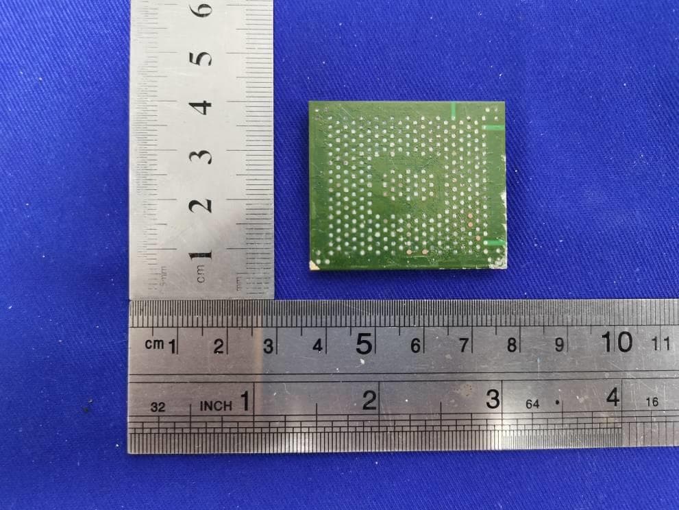
LHJ-HM28NA001
May 04, 2023HM28NA-001
Equipment Class
CXX - Communications Rcvr for use w/ licensed Tx and CBs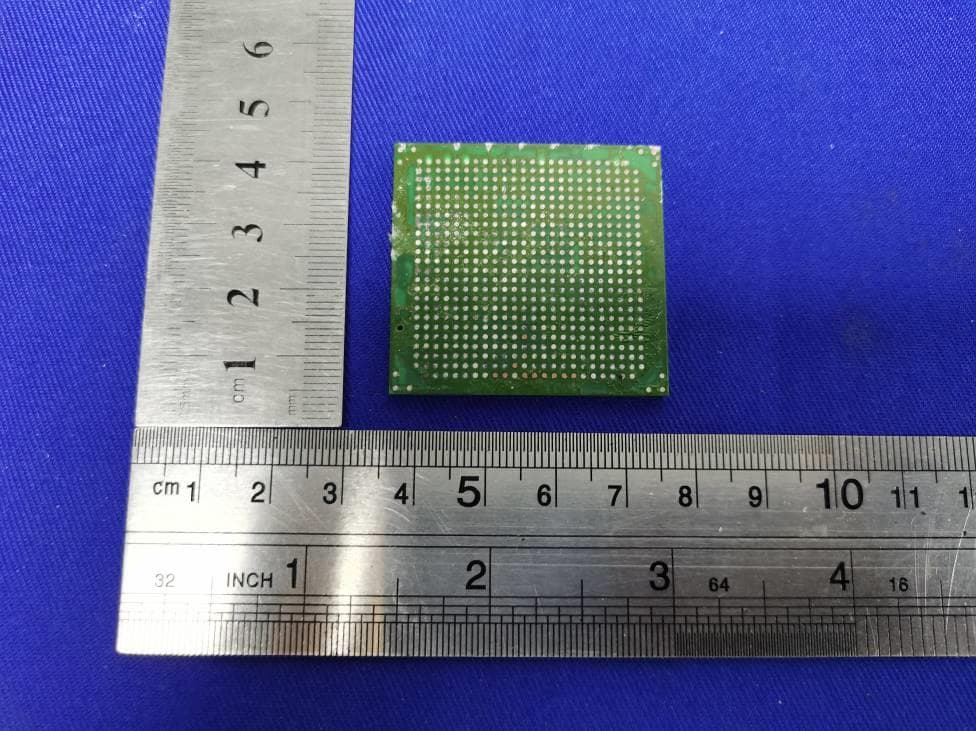
LHJ-FE3RW0051
Jan 07, 2023FE3RW0051
Equipment Class
CXX - Communications Rcvr for use w/ licensed Tx and CBs
LHJ-BL28NARD2
Dec 14, 2022BL28NA-RD2
Equipment Class
PCB - PCS Licensed Transmitter
LHJ-FE5NA0010
Nov 09, 2022FE5NA0010,FE5NA0011
Equipment Class
JBP - Part 15 Class B Computing Device Peripheral