LHJ009Auto Security System Transmitter
Continental Automotive Systems, Inc.
Click to zoom
Application Details
- Equipment Class
- DSC - Part 15 Security/Remote Control Transmitter
- Date of Grant
- Oct 20, 1998
- Application Purpose
- Original Equipment
- Date of Application
- Sep 21, 1998
- Equipment Note
- Auto Security System Transmitter
- Frequency Range
- 315.00000000 - 315.00000000
- Country
- United States
Documents & Files
Document Text
Text extracted from the exhibit documents filed with the FCC. Open a document above to read the original.
Users Manual
Motorola AIEG LS Keyless Entry Transmitter Model 90584373 FCC ID: LHJ009 User’ Manual Parking lotIf you park in a lot where someone will be watching your vehicle, it's best to lock it up and take your keys. But what if you h ave to leave your ignition key?• If possible, park in a busy, well lit area.• Put your valuables in a storage area, like your trunk or glovebox. If your vehicle has a center arm rest storage area, put yo ur valuables in it. Be sure to close and lock the storage area.• Close all windows.• Move the remote trunk release lockout lever to the "ON” position.• Lock all the doors except the driver's.• Then take the Saturn Security System transmitter with you.SATURN SECURITY SYSTEM/REMOTE KEYLESS ENTRY (OPTION) LS keyless entry transmitter The Saturn Security System provides both an anti-theft feature and a starter disable feature for your Saturn.You will have the ability to lock and unlock your doors or release your tr unk (liftgate for the wagon) when approaching or leaving your Saturn from a distance of up to 26 ft. (8 m.) using your key chain remote transmittersupplied with the Saturn Security System.Additional features of the Saturn Security System include active security system arming, passive security systemarming (programmed in by the retailer), and illuminated entry.The Saturn Security System consists of a receiver, which is located in your Saturn and two transmitters. The receivercan be programmed with up to four transmitters. Additional transmitters can be purchased at your Saturn retailer.Your Saturn Security System operates on a radio frequency subject to Federal Communications Commission (FCC)Rules and Industry Canada radiocommunication regulations.This device complies with Part 15 of the FCC Rules. Operation is subject to the following two conditions: ( 1 ) thisdevice may not cause harmful interference, and (2) this device must accept any interference received includinginterference that may cause undesired operation. This device complies with RSS-210 of Industry Canada radiocommunication regulations. Operation is subject to thefollowing two conditions: (I ) this device may not cause interference, and (2) this device must accept anyinterference received including interference that may cause undesired operation of the device.Changes or modifications to this system by other than an authorized service facility could void authorization to usethis equipment. Active and Passive Arming of the Saturn Security SystemActive arming of the Saturn Security System requires you to press the "LOCK" button on your transmitter in order toarm the Saturn Security System. Passive arming of the Saturn Security System does not require you to press the"LOCK" button on your transmitter to arm the system, however, you may press the "LOCK" button on thetransmitter to arm the system right away instead of waiting the one minute for the system to arm itself.The Saturn Security System can be programmed to be in either the active arming mode or the passive arming mode.It is not possible to have both modes turned on at the same time. Your Saturn will be set to the active arming modefrom the manufacturer.Contact your Saturn retailer to program your Saturn to the passive arming mode or to turn these modes on or off. The following sections will explain how both arming modes work. Active Arming of the Saturn Security System"LOCK" (Saturn Security System Arms)You must press the "LOCK" button on your key chain transmitter in order to arm the Saturn Security System. Whenyou press the "LOCK" button on your transmitter, all doors will lock, the Saturn Security System will armautomatically, and the dome lamp will flash twice. If you press the "LOCK" button again within five seconds afterthe first press, the horn will chirp to let you know that the Saturn Security System has armed.If a door is open when you press the "LOCK" button, the doors will lock, but the Saturn Security System will notarm until all the doors are closed. Once the doors are closed, the Saturn Security System will arm and the domelaptop will flash twice to let you know the system is armed. The horn will not chirp even after all the doors areclosed. To get the horn to chirp if a door was open during the arming process, you must press the "LOCK" button onyour transmitter twice after the doors are closed."UNLOCK" (Saturn Security System Disarms) When you press the "UNLOCK" button on your transmitter once, the driver side door will unlock, the Saturn Security System will disarm, and the dome lamp will come on. If you press the "UNLOCK" button again within five seconds of the first press, the rest of the doors will unlock. Passive Arming of the Saturn Security System Lock (All Doors Lock; Saturn Security System Does Not Arm ) When the Saturn Security System on your car is set to the passive arming mode, it will arm one of two ways. They are as follows; 1 In the passive arming mode, the system will arm itself in one minute after the ignition key is turned to the "LOCK position, and you can open and shut the car door. For example, when you stop your car, turn the ignition key tothe "LOCK" position, remove the key and exit the car. Immediately after you shut the door, the security systemclock will begin to count down, and after one minute has passed, the Saturn Security System will arm itself. (Thedoors will not lock automatically ) 2. The Saturn Security System will delay automatic arming for ten minutes after the ignition key is turned to the "LOCK" position if you do not open and close the door. For example, if you stop your car, turn the ignition keyto the "LOCK" position and remove the key, but decide to sit in your car instead of getting out and closing thedoor, the Saturn Security System will arm after ten minutes. This is meant to give you some time to collect yourthings and exit the car without setting off the alarm. When in the passive arming mode, the door locks will not lock automatically. You must press the interior door lockswitc…
Text truncated - open the document above for the full version.
Cover Letter(s)
Page 1 of 1 September 22, 1998 Federal Communications Commission APPLICANT: MOTOROLA REFERENCE FCC ID: LHJ009 731 Confirmation Number: EA91821 Correspondance ID: None The following information was mistakenly excluded from the Electronic 731 form. The Rated RF power output is 0.02 mW. The Frequency tolerance is 0.0125% The Emissions designator is 60KM1D Please do not hesitate to contact me if there are any further questions with the submittal. My phone number is 815-293-0772 and Fax is 815-293-0820. Sincerely, Joseph Strzelecki, NCE Radiometrics Midwest Corporation Authorized Agent for Motorola E-Mail: [email protected]
ID Label/Location Info
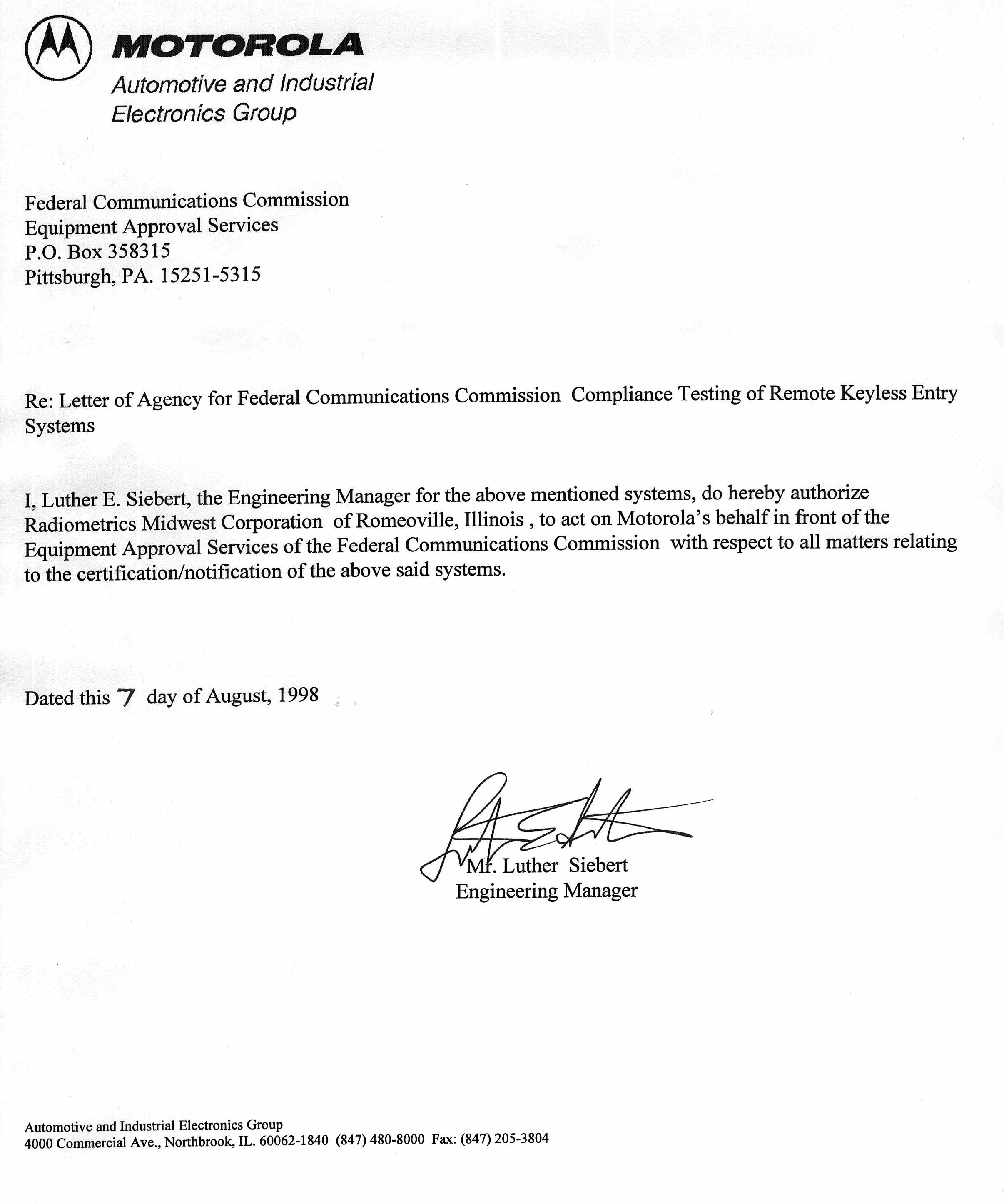
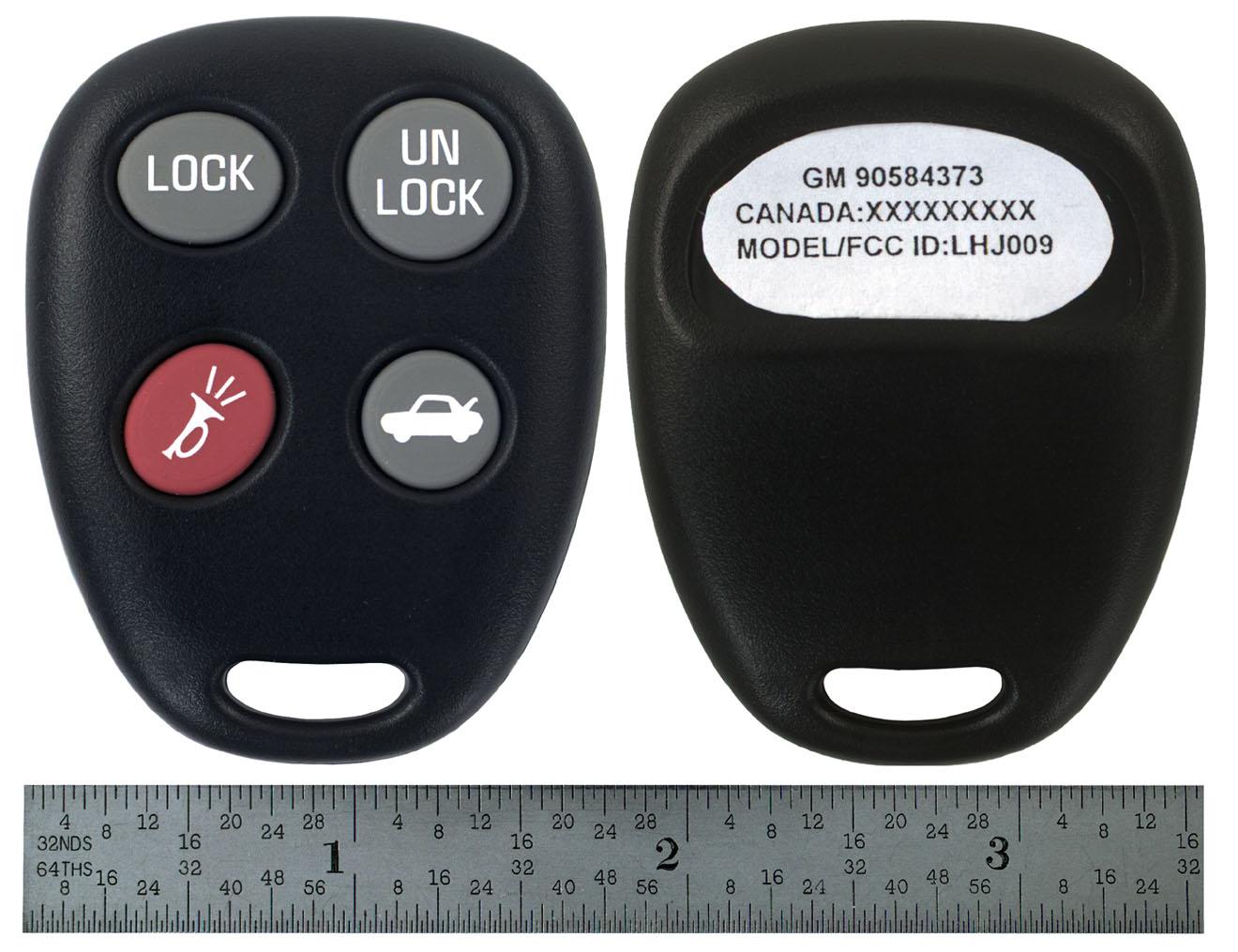
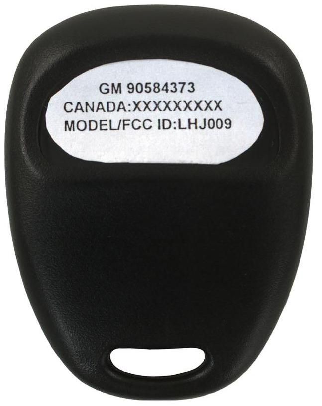
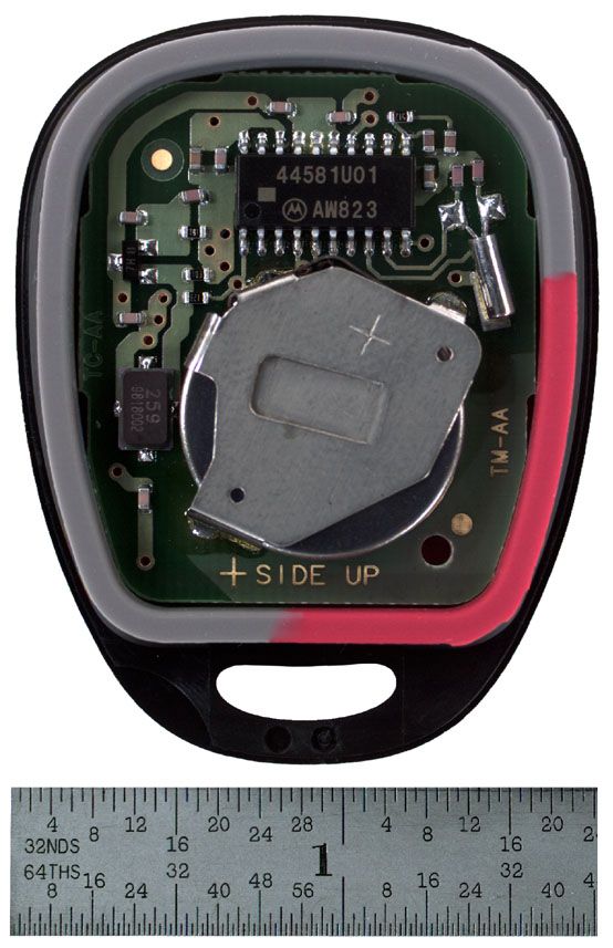
FCC ID: LHJ009 Page 1 of 1 FCC LABEL The label is molded directly into the plastic of the EUT. Motorola RFA Transmitter Label |-----14.0 mm----| GM 90584373 ] 1.875mm CANADA: XXXXXXXXX ] 1.875mm MODEL/FCC ID: LHJ009 ] 1.875mm See Photo attachement for label placement on EUT The following compliance statement is listed in the user’s manual. This device complies with Part 15 of the FCC Rules. Operation is subject to the following two conditions: ( 1 ) this device may not cause harmful interference, and (2) this device must accept any interference received including interference that may cause undesired operation.
Operational Description
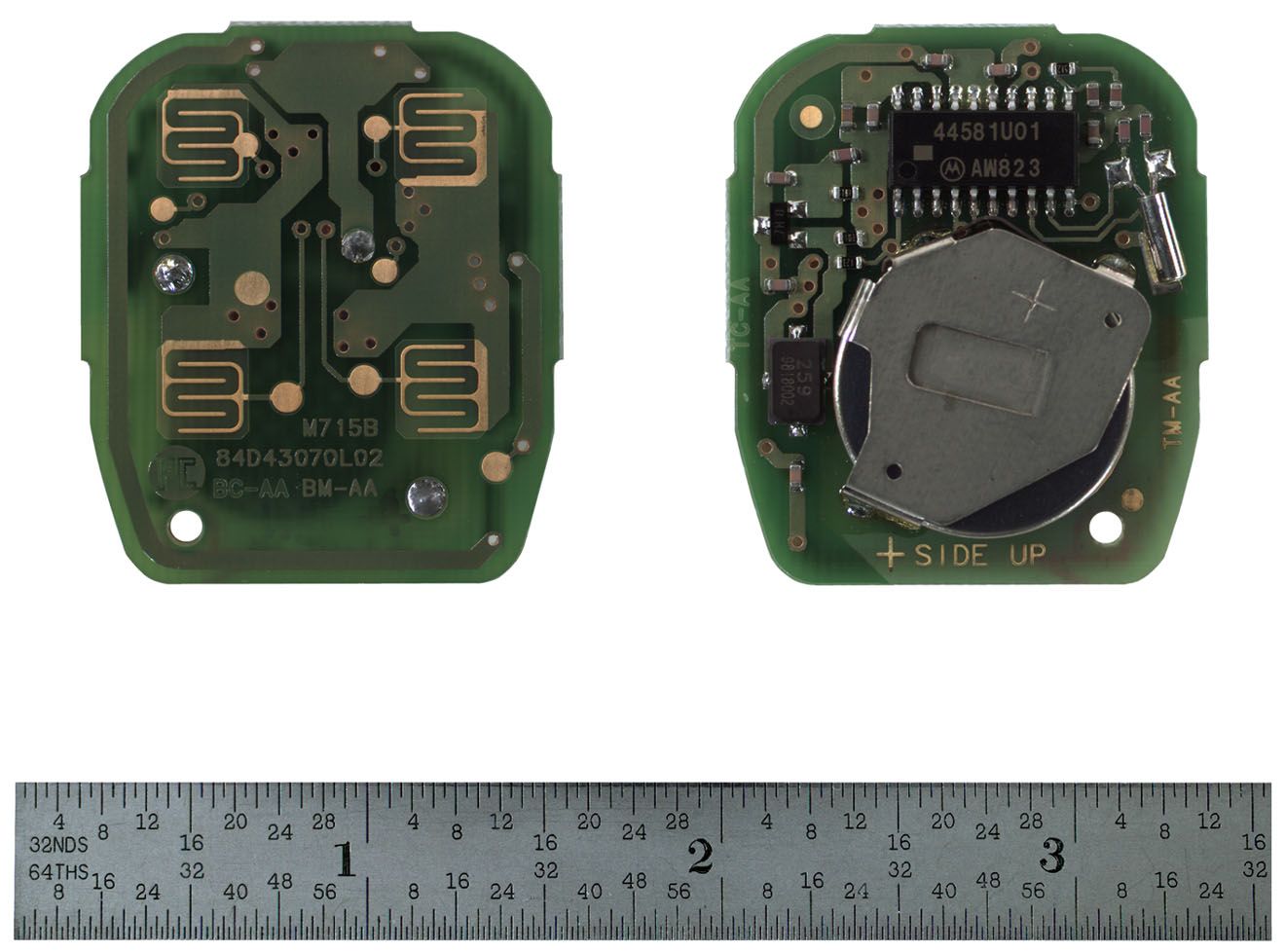
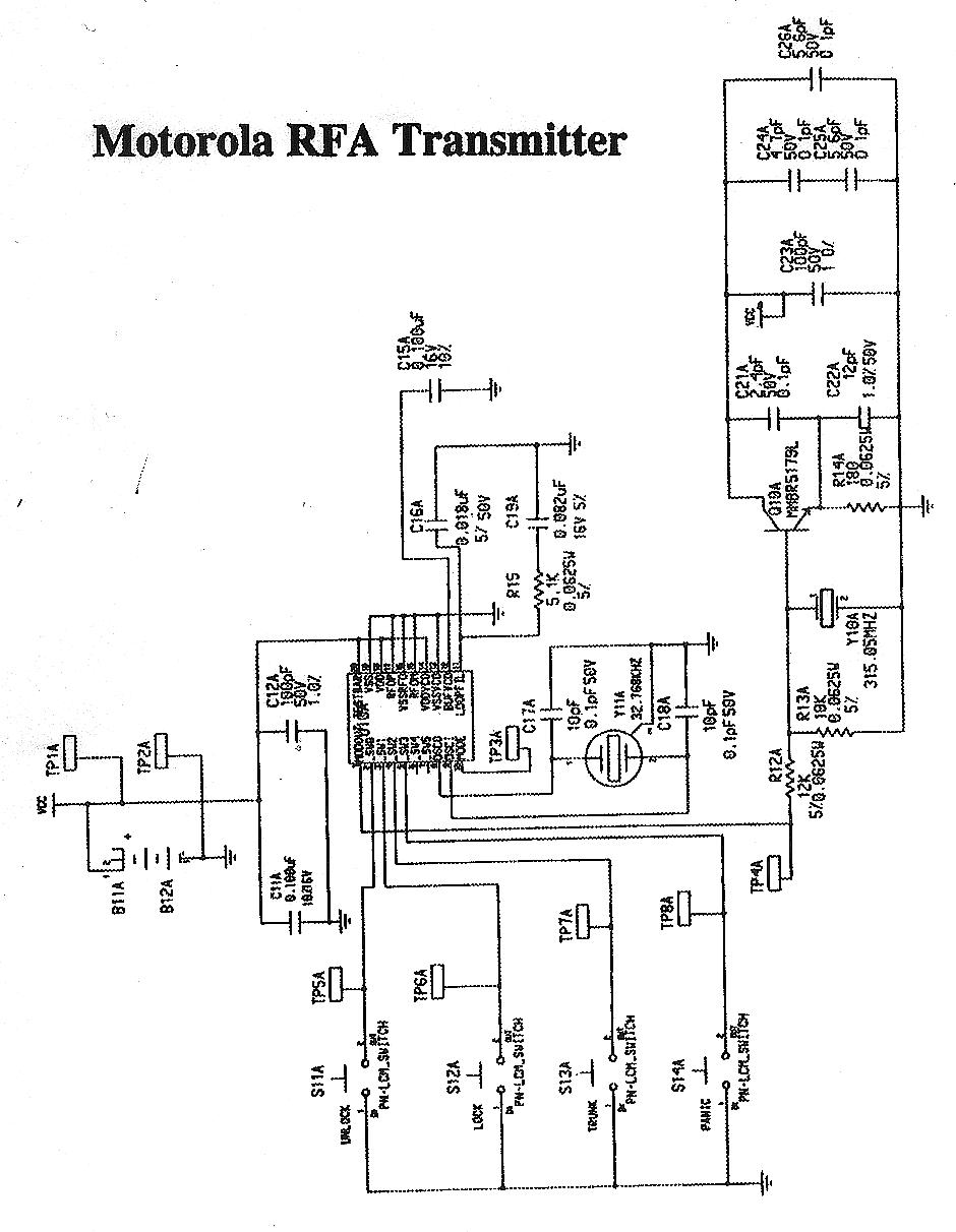
FCC ID: LHJ009 Page 1 of 1 1) Technical Description The Transmitter consists of four momentary push button switches, an RF oscillator (315Mhz SAW based), a single 3V lithium coin cell battery, and a custom IC. In normal use nothing occurs until one of the four buttons is pressed. The custom IC determines which button was activated, then constructs the correct digital message which is sent to the RF oscillator at a 2 kHz rate. The RF oscillator is a simple ON-OFF Keyed stage. Once the transmission is complete the custom IC goes into a standby mode and remains inactive until the next button is pressed.
Test Report
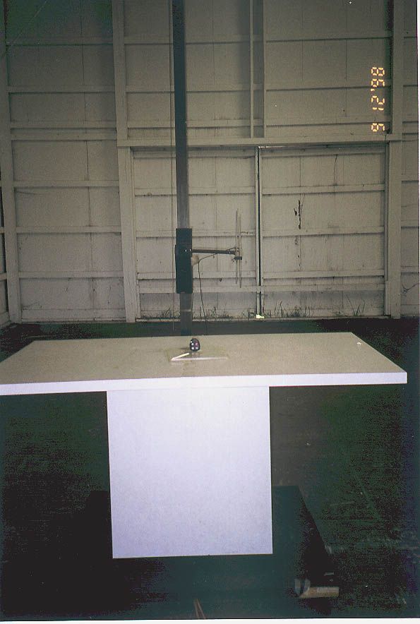
315 MHz Transmitter Radiometrics Midwest Corporation Test Document RP-3880A Issue Date: September 18, 1998 This report concerns: Original grant Equipment type: Periodic Transmitter Transition Rules per 15.37 are not requested. Tests Performed ForTest Facility Motorola AIEG 4000 Commercial Av. Northbrook, IL 60062-1840 Radiometrics Midwest Corporation 12 East Devonwood Romeoville, IL 60446 Phone: (815) 293-0772 FAX: (815) 293-0820 [email protected] Test Report Written ByTest Report Approved By Joseph Strzelecki Senior EMC Engineer NARTE EMC-000877-NE Chris W. Carlson Director of Engineering NARTE EMC-000921-NE MEASUREMENT/TECHNICAL REPORT Motorola AIEG Model 90584373 FCC ID: LHJ009 APPLICATION FOR CERTIFICATION RF Emission Measurements Performed For Determination of Compliance with the US Code of Federal Regulations Title 47, Chapter I, FCC Part 15 Subpart B As Required for Certification for Unintentional Radiators Tests Performed ForFCC IDRadiometrics Test DocumentPage Motorola AIEG LHJ009RP-3880A2 of 10 Table of Contents 1.0 General Information ..................................................................................................................3 1.1 Product Description ...............................................................................................................3 1.2 Related Submittals ................................................................................................................3 1.3 Tested System Details...........................................................................................................3 1.4 Test Methodology ..................................................................................................................3 1.5 Test Facility............................................................................................................................3 1.6 Test Equipment .....................................................................................................................4 2.0 System Test Configuration........................................................................................................4 2.1 Test System and Justification ................................................................................................4 2.2 EUT Test Configuration ............................................................................................................4 2.3 Special Accessories...............................................................................................................4 2.4 Equipment Modifications........................................................................................................4 Figure 2.1 Configuration of Tested System .................................................................................5 3.0 Occupied Bandwidth Data ........................................................................................................6 Figure 3.1 Occupied Bandwidth Plot ...........................................................................................7 4.0 Radiated Emissions Data..........................................................................................................8 4.1 Field Strength Calculation......................................................................................................9 4.2 Peak to Average Calculations................................................................................................9 Figure 4.1 Duty Cycle Plot .........................................................................................................10 Notice: This report must not be reproduced (except in full) without the written approval of Radiometrics Midwest Corporation. Tests Performed ForFCC IDRadiometrics Test DocumentPage Motorola AIEG LHJ009RP-3880A3 of 10 1.0 General Information 1.1 Product Description The Model 90584373 (referred to as the EUT in this report) is a 315 MHz Transmitter. The EUT is manufactured by Motorola AIEG. The EUT consists of four momentary push button switches, an RF oscillator (315Mhz SAW based), a single 3V lithium coin cell battery, and a custom IC. In normal use nothing occurs until one of the four buttons is pressed. The custom IC determines which button was activated, then constructs the correct digital message which is sent to the RF oscillator at a 2Khz rate. The RF oscillator is a simple ON-OFF Keyed stage. Once the transmission is complete the custom IC goes into a standby mode and remains inactive until the next button is pressed. 1.2 Related Submittals Motorola AIEG has previously submitted the associated receiver pursuant to the Notification equipment authorization as FCC ID: LHJ008. 1.3 Tested System Details The identification for the EUT is as follows. Model Number Serial NumberFCC ID Manufacturer & Description Cable Descriptions M/N: 90584373 (EUT) LHJ009Motorola AIEG 315 MHz Transmitter No cables can be connected to the EUT 1.4 Test Methodology The test procedures used are in accordance with the ANSI document C63.4-1992, (July 17, 1992) "Methods of Measurement of Radio Noise Emissions from Low-Voltage Electrical and Electronic Equipment in the Range of 9 kHz to 40 GHz". The specific procedures are described herein. Radiated testing was performed at an antenna to EUT distance of 3 meters. The antenna was raised and lowered from 1 to 4 meters. 1.5 Test Facility The open area test site used to collect the radiated data is located on 8625 Helmar Road in Newark, Illinois. The open field test site has a metal ground screen. Details of the site characteristics are on file with the FCC. Conducted emission measurements and preliminary radiated emission scans were performed in shielded enclosure “B” at Radiometrics' Romeoville, Illinois EMI test lab. These sites have been fully described in a report and accepted by the FCC in a letter dated October 1, 1996 (31040/SIT 1300F2). Tests Performed ForFCC IDRadiometrics Test DocumentPage Motorola AIEG LHJ009RP-3880A4 of …
Text truncated - open the document above for the full version.
Contact Information
Applicant
James Zhang
Technical Contact
Radiometrics Midwest CorporationJoseph R Strzelecki
[email protected]815-293-0772
12 East Devonwood Av. · Romeoville, Illinois · United States
Non-Technical Contact
Radiometrics Midwest CorporationJoan E Strzelecki
[email protected]815-293-0772
Test Firm
Radiometrics Midwest CorporationJoseph Strzelecki
815-293-0772Fax: 815-293-0820
Technical Specifications
| # | Rule Parts | Frequency Range | Power Output |
|---|---|---|---|
| 1 | 15C | 315 MHz - 315 MHz | - |
Other Applications from Continental Automotive Systems, Inc.
LHJ-FE5RW0020
May 15, 2026FE5RW0020
Equipment Class
PCB - PCS Licensed Transmitter
LHJ-HM28NA001
May 04, 2023HM28NA-001
Equipment Class
CXX - Communications Rcvr for use w/ licensed Tx and CBs
LHJ-FE3RW0051
Jan 07, 2023FE3RW0051
Equipment Class
CXX - Communications Rcvr for use w/ licensed Tx and CBs
LHJ-BL28NARD2
Dec 14, 2022BL28NA-RD2
Equipment Class
PCB - PCS Licensed Transmitter
LHJ-FE5NA0010
Nov 09, 2022FE5NA0010,FE5NA0011
Equipment Class
JBP - Part 15 Class B Computing Device Peripheral