LHJGEN80CNTTelematics device used in Vehicle
Continental Automotive Systems, Inc.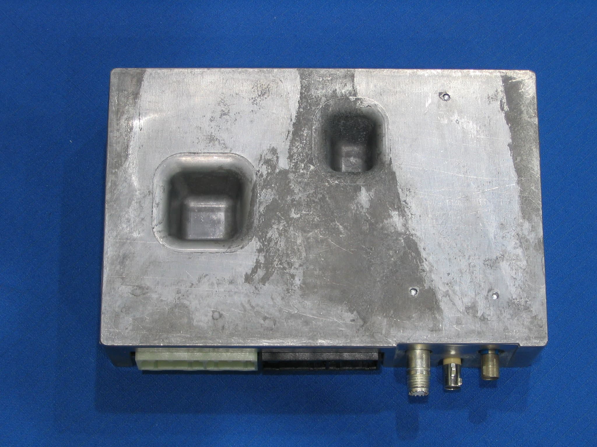
Click to zoom
Application Details
- Equipment Class
- PCB - PCS Licensed Transmitter
- Date of Grant
- Jan 16, 2008
- Application Purpose
- Original Equipment
- Date of Application
- Jan 16, 2008
- Equipment Note
- Telematics device used in Vehicle
- Frequency Range
- 1850.00000000 - 1910.00000000
- Country
- United States
Documents & Files
Document Text
Text extracted from the exhibit documents filed with the FCC. Open a document above to read the original.
Users Manual
Welcome to OnStar. Welcome. Congratulations on your purchase of an OnStar-equipped General Motors vehicle! With all the services OnStar can provide you, you’ll enjoy greater peace of mind when you travel. You’ll find services from Remote Door Unlock, to Automatic crash notification and Turn-by-Turn Navigation. And, you can make and recieve calls using OnStar Hands- Free Calling! OnStar can make your travels safer and more convenient. This Owner Guide will assist you in becoming familiar with all the services OnStar provides, so keep it in your vehicle for reference. If you need further assistance, push the blue OnStar button to speak with a specially trained OnStar Advisor 24 hours a day, 365 days a year. There’s never a charge to ask a question or talk to an Advisor, it’s all part of your OnStar subscription. Thank you for choosing an OnStar-equipped vehicle! t h e b l u e b u t t o n t h e e m e r g e n c y b u t t o n t h e h a n d s-f r e e b u t t o n g e n e r a l i n f o r m a t i o n Owner Guides are available in Spanish and French languages. Visit www.onstar.com. Your vehicle can be programmed to respond in French or Spanish language, just push the OnStar button and ask an Advisor. OnStar Advisors can speak French or Spanish as well. You can also learn how OnStar works by listening to the enclosed audio CD. You’ll hear live examples about how to make calls, storenumbers and how the available OnStar Turn-byTurn Navigation works. Table of Contents System status light . . . . . . . . . . . . . . . . . . . . . . . . . . . . . . . . . . . 3 What services you get: • with the Safe & Sound Plan . . . . . . . . . . . . . . . . . . . . . . . 6-9 ■ • with the Directions & Connections Plan . . . . . . . . . . 10-11 ■ OnStar Turn-by-Turn Navigation . . . . . . . . . . . . . . . . . . . . 12-19 ■ Emergency Services . . . . . . . . . . . . . . . . . . . . . . . . . . . . . . 20-23 ■ Hands-Free Calling: • how to make calls . . . . . . . . . . . . . . . . . . . . . . . . . . . . . . . . . 25 ■ • storing numbers . . . . . . . . . . . . . . . . . . . . . . . . . . . . . . . . . . 26 ■ • getting your vehicle’s number . . . . . . . . . . . . . . . . . . . . . . 27 ■ Voice recognition troubleshooting . . . . . . . . . . . . . . . . . . . . . 28 ■ Virtual Advisor (traffic, weather & stocks) . . . . . . . . . . . . . . 37 ■ onstar .com . . . . . . . . . . . . . . . . . . . . . . . . . . . . . . . . . . . . . . . . . 38 Renewing your subscription . . . . . . . . . . . . . . . . . . . . . . . . . . 38 Potential Issues . . . . . . . . . . . . . . . . . . . . . . . . . . . . . . . . . . 40-43 Index . . . . . . . . . . . . . . . . . . . . . . . . . . . . . . . . . . . . . . . . . . . 44-45 OnStar Owner’s Guide It begins with the blue button. Push this button now and you’ll be connected to a specially trained OnStar Advisor who can verify all of your account information and can answer any questions you may have. • Most new OnStar-equipped vehicles come with a one-year subscription to the Safe & Sound Plan. Some GM Certified Used Vehicles come with a shorter trial subscription, or on any pre-owned vehicle you can easily start a new subscription. • If your vehicle comes with the one-year Directions & Connections Plan, or if you choose to upgrade to this service plan, an Advisor can download Turn-by-Turn driving directions, or give you driving directions, find millions of addresses, businesses or restaurants, and provide other connection services. Red Emergency Button In an emergency, push this button to get help from specially trained OnStar Emergency Advisors. • If you are having an emergency or if you are in an accident. • To be a Good Samaritan or to respond to an AMBER Alert. Hands-Free Calling Button We’ve made staying in touch on the road safe and easy with hands-free, voice-activated calling* that’s built right into your vehicle. • Use this button to make a call or end a call. • To answer an incoming call. • To give OnStar Turn-by-Turn Navigation voice commands. • To access Virtual Advisor for location based traffic, weather and stock reports. 2 3 System Status To the right of the OnStar buttons is a System Status light. Your vehicle runs an OnStar systems check every time you start up. This light is designed to indicate to you that your OnStar system is active and ready to make calls. On vehicles with an automatic dimming rearview mirror, the green light on the left side of the buttons indicates that the automatic dimming function is on. Solid Green - indicates the OnStar system is fully functional and ready to make or receive calls. Flashing Green - when you are on a phone call or when someone is calling you, the green light will flash. Red - indicates that your OnStar system has detected a problem within the system. Push your OnStar button and ask an OnStar Advisor to run a diagnostic check. If you cannot connect to OnStar please visit a dealer for service as soon as possible. No Light - this indicates that your OnStar subscription is not active or has expired. All services have been deactivated and are not functional. Push the blue OnStar button and wait until your system connects to an Advisor who can renew your subscription. See page 38 for subscription information. * OnStar Hands-Free Calling requires a Hands-Free enabled vehicle, existing OnStar service contract and prepaid minutes or enrollment in a shared minutes plan. Not available in certain markets. Calls may be made to the US and Canada only. See “Additional Information” section on pages 38-39 for system limitations and details. To find out what OnStar can do for you, just push the blue button. Most new vehicles come with one year of OnStar service, available 24/7. There are two levels of service – the Safe & Sound Plan and the Directions & Connections Plan. Both plans come with all the Emergency services, Safe & Sound services and the Hands-Free Calling feature. The uplevel Directions & Connections Plan adds driving directions delivered b…
Text truncated - open the document above for the full version.
Cover Letter(s)
FCCID: LHJGEN80CNT
External Photos
Figure 1: Top Side Figure 2: Bottom Side This Connector is not present in the non-bluetooth version of this product. Figure 3: Cabled Side This Connector is not present in the non-bluetooth version of this product.
Internal Photos
Figure 1: Top Side With Cover Rem oved (Bottom Side of Main PCB) Figure 2: Main PCB Removed (Top Side) Figure 3: Daughter Board Location in Chassis Figure 4: Daughter Board Top Side Figure 5: Daughter Board Top Side With Shields Removed Figure 6: Daughter Board Bottom Side Figure 7: Daughter Board Bottom Side With Shields Removed
Test Report
This report is for the exclusive use of Intertek's Client and is provided pursuant to the agreement between Intertek and its Client. Intertek's responsibility and liability are limited to the terms and conditions of the agreement. Intertek assumes no liability to any party, other than to the Client in accordance with the agreement, for any loss, expense or damage occasioned by the use of this report. Only the Client is authorized to copy or distribute this report and then only in its entirety. Any use of the Intertek name or one of its marks for the sale or advertisement of the tested material, product or service must first be approved in writing by Intertek. The observations and test results in this report are relevant only to the sample tested. This report by itself does not imply that the material, product, or service is or has ever been under an Intertek certification program. TEST REPORT Report Number: 3134607LEX-003 Project Number: 3134607 Evaluation of the G80050AUAL Model Number: G80050AUAL FCC ID: LHJGEN80CNT Industry Canada ID: 2807E-GEN80CNT FCC Part 22 Subpart H FCC Part 24 Subpart E FCC Part 15 Subpart B RSS-129 RSS-133 For Continental Automotive Systems Test Performed by: Test Authorized by: Intertek 731 Enterprise Drive Lexington, KY 40510 Continental Automotive Systems 21440 West Lake Cook Road Deer Park, IL 60010 Prepared By:_______________________________Date:____1/3/2008________ Bryan C. Taylor, EMC Team Leader Approved By:______________________________Date:____1/3/2008_________ Jason Centers, Senior Project Engineer Intertek 731 Enterprise Drive, Lexington, KY 40510 Telephone: 859-226-1000 Fax: 859-226-1040 Web: www.etlsemko.com 731 Enterprise Drive, Lexington KY 40510 Evaluation For:Continental Automotive Systems FCC ID: LHJGEN80CNT Model No: G80050AUAL ICID:2807E-GEN80CNT Report Number: 3134607LEX-003 Page 2 of 48 FCC Part 22H, 24E, and 15B Evaluation TABLE OF CONTENTS 1 JOB DESCRIPTION .......................................................................................................................... 4 1.1 COMPANY INFORMATION............................................................................................................ 4 1.2 TEST SAMPLE INFORMATION....................................................................................................... 4 1.3 SYSTEM SUPPORT EQUIPMENT.................................................................................................... 5 1.4 CABLES USED DURING TESTING................................................................................................. 5 1.5 SYSTEM BLOCK DIAGRAM(S) ...................................................................................................... 6 1.6 MODE(S) OF OPERATION / ENGINEERING JUDGMENTS................................................................ 6 2 EXECUTIVE SUMMARY................................................................................................................. 7 2.1 MODIFICATIONS REQUIRED FOR COMPLIANCE............................................................................ 8 3 TEST FACILITY................................................................................................................................ 9 3.1 TEST EQUIPMENT......................................................................................................................... 9 4 CONDUCTED RF POWER ............................................................................................................ 10 4.1 TEST PROCEDURE...................................................................................................................... 10 4.2 TEST RESULTS........................................................................................................................... 10 5 RADIATED RF POWER ................................................................................................................. 11 5.1 TEST PROCEDURE...................................................................................................................... 11 5.2 TEST RESULTS........................................................................................................................... 11 6 MAXIMUM PERMISSIBLE EXPOSURE (MPE) CALCULATIONS ...................................... 12 6.1 CALCULATIONS.......................................................................................................................... 12 6.2 TEST RESULTS........................................................................................................................... 12 7 EMISSION LIMITATIONS, OCCUPIED BANDWIDTH .......................................................... 13 7.1 TEST PROCEDURE...................................................................................................................... 13 7.2 TEST RESULTS........................................................................................................................... 13 8 OUT OF BAND EMISSION AT ANTENNA TERMINALS........................................................ 17 8.1 TEST PROCEDURE...................................................................................................................... 17 8.2 TEST RESULTS........................................................................................................................... 18 9 RADIATED SPURIOUS EMISSIONS ........................................................................................... 33 9.1 TEST PROCEDURE...................................................................................................................... 33 9.2 TEST RESULTS........................................................................................................................... 33 10 MODULATION LIMITING, TX AUDIO FREQUENCY RESPONSE, SIDEBAND POWER ATTENUATION....................................................................................................................... 39 731 Enterprise Dr…
Text truncated - open the document above for the full version.
Contact Information
Applicant
James Zhang
Technical Contact
Continental Automotive SystemsKevin Krishnaratne
[email protected]8478622543
21440 West Lake Cook Rd · Deer Park, Illinois · United States
Technical Specifications
| # | Rule Parts | Frequency Range | Power Output | Emission | Tolerance |
|---|---|---|---|---|---|
| 4 | 24E | 1.85 GHz - 1.91 GHz | 370.00 mW | 1M25F9W | 0.07 ppm |
Other Applications from Continental Automotive Systems, Inc.
LHJ-FE5RW0020
May 15, 2026FE5RW0020
Equipment Class
PCB - PCS Licensed Transmitter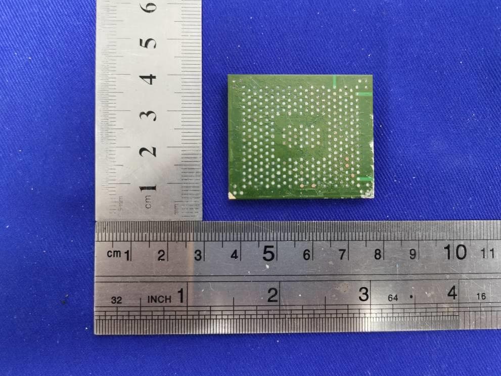
LHJ-HM28NA001
May 04, 2023HM28NA-001
Equipment Class
CXX - Communications Rcvr for use w/ licensed Tx and CBs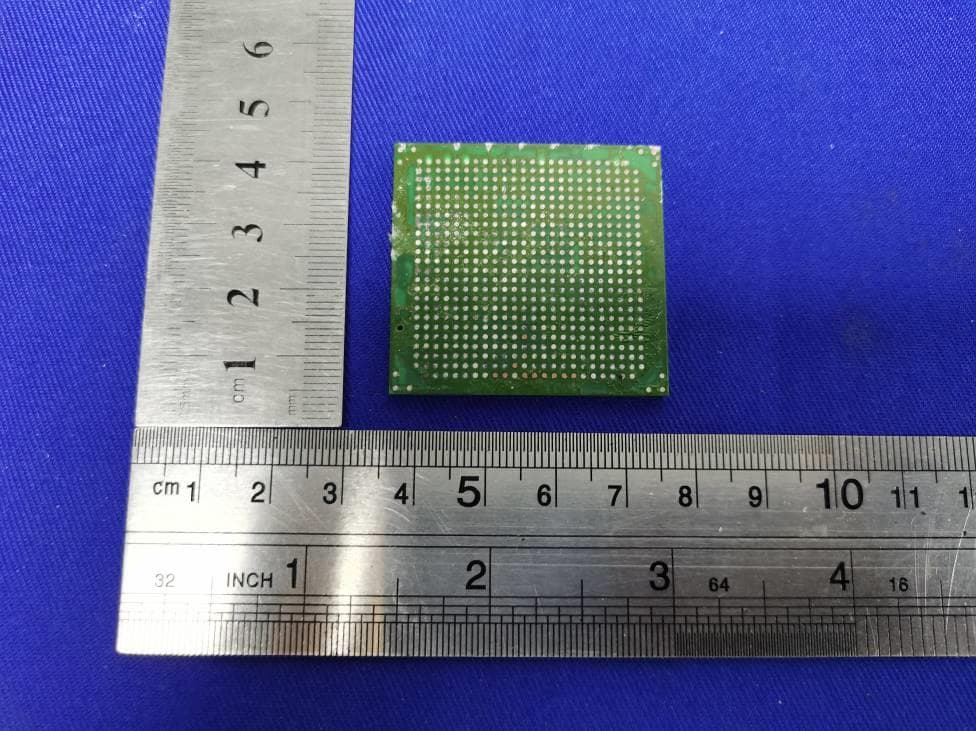
LHJ-FE3RW0051
Jan 07, 2023FE3RW0051
Equipment Class
CXX - Communications Rcvr for use w/ licensed Tx and CBs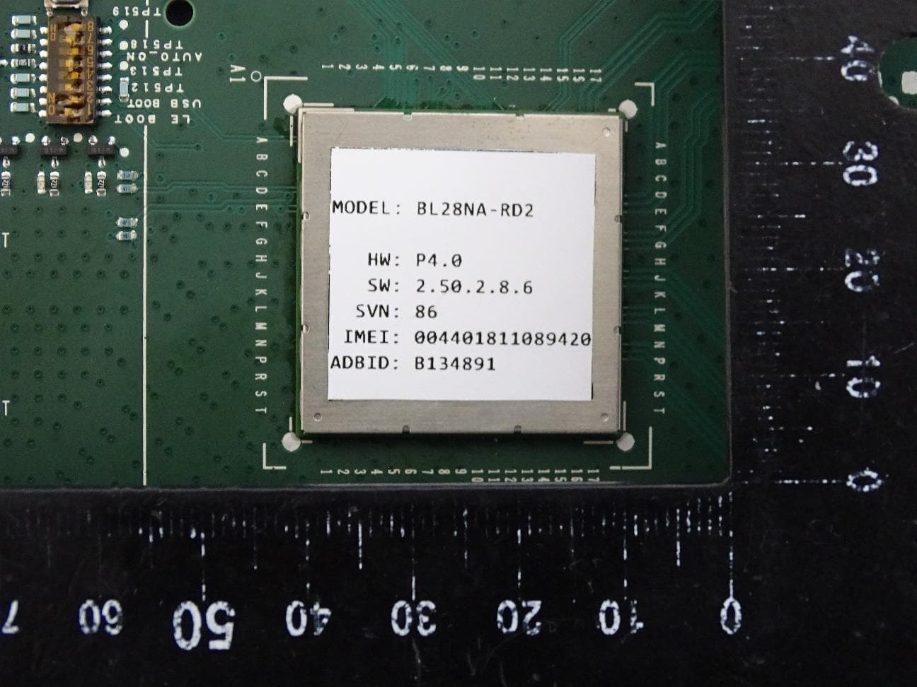
LHJ-BL28NARD2
Dec 14, 2022BL28NA-RD2
Equipment Class
PCB - PCS Licensed Transmitter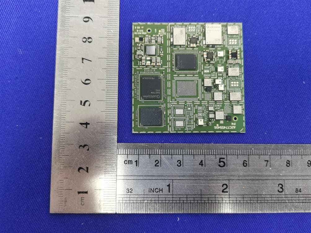
LHJ-FE5NA0010
Nov 09, 2022FE5NA0010,FE5NA0011
Equipment Class
JBP - Part 15 Class B Computing Device Peripheral