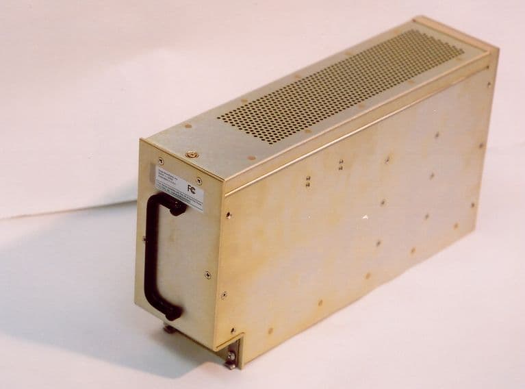
LOK150-TX-UHS-2Extend-A-Page
Universal Repeater, LLC
Click to zoom
Application Details
- Equipment Class
- TNB - Licensed Non-Broadcast Station Transmitter
- Date of Grant
- Nov 10, 2004
- Application Purpose
- Original Equipment
- Date of Application
- Nov 10, 2004
- Equipment Note
- Extend-A-Page
- Frequency Range
- 150.00000000 - 174.00000000
- Company
- Universal Repeater, LLC
- Country
- United States
Documents & Files
Document Text
Text extracted from the exhibit documents filed with the FCC. Open a document above to read the original.
Users Manual
Extend-A-Page VHF Transmitter System Manual EAGLE BROADBAND, INC. 101 Courageous Drive League City, TX 77538 Telephone: (281) 538-6000 Fax: (281) 334-5302 Toll Free: 1-800-628-3910 www.eaglebroadband.com Table of Contents Page Preface. i Limited Warranty iii 1 Introduction 1-1 Transmitter 1-2 General 1-2 2 Specifications 2-1 2.1 VHF Exciter 2-1 2.2 General 2-1 3 Installation 3-1 3.1 Safety Regulation 3-1 3.1.1 FCC Requirements 3-1 3.1.2 FCC Interference Warning 3-1 3.1.3 OSHA Safety Standards 3-2 3.1.4 Lighting Protection Consideration 3-2 3.1.5 Integrated Circuit Handling Procedure 3-3 3.1.6 Equipment Unpacking & Inspection 3-3 3.2 Installation Procedure 3-4 4 Technical Description 4-1 4.1 Control U Board 4-1 4.2 Extend-A-Page Transmitter Unit Exciter 4-1 4.2.1 Exciter Control Board 4-2 4.2.1.1 Circuit Description 4-2 4.2.1.2 Frequency Determining and Stabilization 4-3 4.2.2 Exciter Board Circuit Description 4-4 4.2.2.1 Channel Phase-Locked Loop (PLL) 4-4 4.2.2.2 Upconverter 4-6 4.3 Front Panel Display Board 4-8 4.4 Power Supply 4-8 A - Extend-A-Page Appendix Table of Contents A-1 Preface Version 4 i 04/02/04 Preface Scope The Extend-A-Page Technical Manual contains detailed information regarding the system installation and technical description of the Extend-A-Page receiver and transmitter. The scope of this document is to provide the reader with a general understanding of the system and features of the Extend-A-Page system. The user of this manual should have a background with similar types of equipment. Copyright This document contains proprietary information protected by copyright. All rights reserved. No part of this document may be photocopied, reproduced, transmitted, transcribed, stored in a retrieval system, or translated into any language in any form by any means, electronic, mechanical, magnetic, optical, chemical, hydraulic, manual or otherwise without prior written consent of EAGLE BROADBAND, INC EAGLE BROADBAND, INC software and firmware programs used in the Extend-A-Page are protected by copyright. Therefore, no software or firmware may be copied or reproduced in any manner written consent of EAGLE BROADBAND, INC Notice Some EAGLE BROADBAND, INC products may be labeled Eagle Telecom International. These are simply trade names for certain EAGLE product lines. EAGLE BROADBAND, INC provides this publication as is with no warranty of any kind, either express or implied including, but not limited to the implied warranties of merchantability or fitness for a particular purpose. Some states do not allow disclaimer or express or implied warranties in certain transactions; therefore, this statement may not apply in all instances. This publication may have technical inaccuracies or typographical errors. Therefore, the information contained in this manual is subject to change or revision. Changes or revisions will be incorporated in all new editions of the publication. EAGLE BROADBAND, INC may at any time make improvements and/or changes in product(s) and/or program(s) described in this publication. Products are stocked at the address below. Requests for copies of this publication and for technical information should be directed to EAGLE BROADBAND, INC. Preface Version 4 ii 04/02/04 Customer Service Eagle Broadband’s Customer Service Department is dedicated to provide complete product support to all its customers. For Technical Assistance only, call the toll-free number 1-800-628-3910, between the hours of 8:00 A.M. and 5:00 P.M. (CST). For non-business hours or International’s calls, call (281) 538-6000 for instructions. If you reach voice mail, please leave a message and your call will be returned promptly. Customers should maintain a stock of replacement parts or units for emergency backup. Eagle Broadband factory trained field service engineers are available for system installation and optimization. For assistance, write or call: EAGLE BROADBAND, INC 101 Courageous Drive, League City, TX 77573 Telephone (281) 538-6000 Fax (281) 334-5302 Toll Free 1-800-628-3910 www.eaglebroadband.com Warranty Version 4 iii 04/02/04 Limited Warranty 1. The product line of paging and mobile equipment, base stations/power amplifiers, receivers, transmitters, security and transmitter control equipment sold by EAGLE BROADBAND INTERNATIONAL, INC. is warranted to the original buyer to meet the then current published specifications, drawings and/or such modifications thereof as Buyer and Seller have agreed to in writing and to be free from defects in workmanship and materials. Seller’s entire warranty obligations are limited to making adjustments by repairing or replacing any product which fails to meet this warranty and which is returned to Seller. Replacement, repairs, or adjustment under this warranty shall be F.O.B. League City, Texas and does not reinstate the warranty set forth herein. Under all circumstances, the warranty will expire not later than one (1) year after date of such first shipment. 2. This warranty is void and adjustment will not be allowed for products which have been subjected to abuse, improper application or installation, unauthorized alteration, or accidental/negligent damage in use, storage, transportation or handling. 3. This warranty does not apply to: a. Incandescent lamps, LEDs, batteries, fuses and other consumable type goods, operable upon arrival only. b. Parts and accessories (other than those in the equipment) sold by Eagle Broadband, Inc. c. Service calls and/or shipping charges necessary to transport the equipment between customer’s location and the factory. d. Routine checkout and/or tuning equipment. e. Equipment damaged by an act of God and/or nature, war or terrorism. f. Equipment that has been sold, rented, or acquired in bankruptcy proceedings. g. Equipment where the serial number has been removed, defaced, or changed. Warranty Version 4 iv 04/02/04 4. The Seller shall have the right of final determination as to the following: (a) existence of cause and defect…
Text truncated - open the document above for the full version.
Users Manual
Appendices Version 4 A-48 4/2/04 +5V TX CONT. PLL DATA LOCK CONT. LOCK DET. 2 LOCK DET 1 IC 3 MOD. AMP 8A15218 U2 VCO-2 Q3 AMPLIFIER 2SC3356 Q2 AMPLIFIER 2SC3356 Q1 AMPLIFIER 2SC3356 150 - 174 MHz J2 OUTPUT D1 DETECTOR HSM107S RV3 POWER SET Q8 AMPLIFIER FMW.1 Q7 CONTROL 2SA1244 Q6 KEY CONT. 2SA1052 LOOP FILTER Q26,Q27 CHARGE PUMP 2SA1052 2SC2462 IC 4 PLL MB1504 Q22,Q23 SWEEP RL1P141C RT1N441C Q24 RIPPLE FIL 2SC2462 Q25 LOCK DET RT1N441C U1 P.D. RPD-1 Q5 AMPLIFIER 2SC3585 Q19 MIXER 2SC3585 Q20 IF AMP. 2SC2620 LOOP FILTER U3 VCO-1 Q28 BUFFER 2SC3585 Q11,Q12 CHARGE PUMP 2SA1052 2SC2462 IC1 PLL MB1504 Q24 RIPPLE FIL 2SC2462 Q25 LOCK DET. RT1N441C Q17 AMPLIFIER 2SC3585 Q18 DOUBLLER 2SC3586 +5v +12V GND +5V Q15 RIPPLE FIL 2SC2462 Q16 BOOSTOR 2SA1244 IC 2 5V REG μPC78L05 J4 10MHz J3 10.7MHz 151-174MHz Q4 DOUBLLER 2SC3356 150 MHz EXCITER BLOCK DIAGRAM PART NO. 100190-045 139.3 - 163.3MHz TO CHARGE PUMP 150- 174 MHz LPF FIGURE 8-F – EXCITER BLOCK DIAGRAM Appendices Version 4 A-49 4/2/04 FIGURE 8-G – EXCITER BOARD ALIGNMENT PROCEDURE 1. Connection Connect the cables from RF unit to J1 (signal and power source), J3 (10.7 MHz) and J4 (10 MHz). Connect a modulation analyzer to J2 (output). 2. Alignment 2-1 VCO 2-1-1. Use a PLL data of the frequency that is actually used for data transmission. Turn power on. While monitoring TP1, adjust the core of the channel VCO for approximately 4V. 2-1-2. While monitoring TP2, adjust the modulation VCO for approximately 4V. 2-2 Modulation 2-2-1. While monitoring TP3, adjust RV1 for 8,5V. 2-2-2. While monitoring a modulated waveform, adjust RV2 for a point where the waveform is sharp and no noise overlapping exists. 2-3 Output Power While monitoring the output power on the modulation analyzer, adjust RV3 for 0.3W output. 3. Verification 3-1. Make sure that the frequency used for alignment is the one that will actually be used for data transmission. 3-2 Make sure that the frequency deviation is less than ±5 KHz. Appendices Version 4 A-50 4/2/04 FIGURE 9 – FREQUENCY DATA STREAM FREQUENCY DATA STREAM 1. PROGRAMMABLE REFERENCE COUNTER MSB LSB 0 0 0 1 0 0 0 0 0 0 0 0 0 0 0 1 PGM DATA PGM CLOCK 4094 STRB PLL STRB 2. COMPARATIVE FREQUENCY MULTIPLIER MSB LSB 0 0 0 1 0 1 1 1 1 1 1 0 0 1 0 1 0 0 0 0 PGM DATA PGM CLOCK 4094 STRB PLL STRB Appendices Version 4 A-51 4/2/04 FIGURE 9 – FREQUENCY DATA STREAM CONT’D FREQUENCY DATA STREAM 2 1. PROGRAMMABLE REFERENCE COUNTER MSB LSB 0 0 0 1 0 0 0 0 0 0 0 0 0 0 0 1 PGM DATA PGM CLOCK 4094 STRB PLL STRB 2. COMPARATIVE FREQUENCY MULTIPLIER MSB LSB 0 0 0 1 0 1 1 1 1 1 1 0 0 1 0 1 0 0 0 0 PGM DATA PGM CLOCK 4094 STRB PLL STRB Appendices Version 4 A-52 4/2/04 FIGURE 10 – PLL BLOCK DIAGRAM T.C.X.O 10.7 MHz MOUDULATED CARRIER EEPROM CPU CH-SW 1/NR P/D P/C S/C 1/NP PRA-SCA CHARGE PUMP L.P.F. BUFF V.C.O BUFF VCO-1 Appendices Version 4 A-53 4/2/04 ENCO synthesizer setup bit values 3FLX150SU.MCD 4-17-02 HAV "Calculate the binary values to load for the Ft-10.7 Mhz loop" fdes1 . 156.210 6 steps7500fref . 3 10 6 PSV164 fdesnt1 fdes1 . 10.710 6 steps fdesr1floor fref steps =fdesnt11.9410 4 =fdesr1400 bvr1 . fdesr121 fdesn1 fdesnt1 PSV1 =fdesn1303.125 n1floor()fdesn1 If Prescaler =32 then set 2^15 =n1303 a1 . ()fdesn1n1PSV1 bvr1if,,PSV1320 2 15 . fdesr121 =a18 bvf1 . n12 8 . a12 =bvf112f10h=bvr1321h If ERZZ = 1 then a1 not integer error condition ERZfloor()a1a1 ERZZif(),,>>0ERZ01 0 =ERZZ0 If ERVV = 1 then a1 > n1 then error condition ERVn1a1 ERVVif(),,>ERV0 0 1 =ERVV0 "Calculate the binary values to load for the 10.7Mhz modulation loop where the prescaler is a divide by 32 " fdes2 . 10.710 6 PSV232fref2 . 10.710 6 steps25000 fdesnt2 fdes2 steps fdesrt2floor fref2 steps =fdesnt2428 =fdesrt2428 fdesn2 fdesnt2 PSV2 If Prescale =32 then set 2^15 n2floor()fdesn2 =n213 bvr2if,,PSV2320 2 15 . fdesrt221 a2 . ()fdesn2n2PSV2 =a212 bvf2 . n22 8 . a22 =bvf2d18h=bvr28359h If ERZZ1 = 1 then a2 not integer then error condition ERZ1floor()a2a2 ERZZ1if(),,>>0ERZ10 10 =ERZZ10 If ERVV1 = 1 then a2 > n2 then error condition ERV1n2a2 ERVV1if(),,<ERV10 1 0 =ERVV10 FIGURE 11 - MATHCAD Appendices Version 4 A-54 4/2/04 LIST 1 – EXTEND-A-PAGE TRANSMITTER REAR PANEL CONNECTOR DESCRIPTION L.1 Extend-A-Page Transmitter Unit System Interface Connector (DB9 to P5 Connector on Motherboard) Db9 Pin # Description 1 – Analog Key (Active Low) 2 – Audio + 3 – Audio - 4 – Digital Key (Active Low) 5 – Digital Data (TTL or RS232) 6 – D-Reset (Active High) 7 – Hotkey (Active Low) 8 – +12VDC Output 9 – Ground NOTES: 1. Both Digital and Analog Key inputs accepts TTL level ‘Low’ or Form C relay closure to ground. 2. Digital Data accepts both TTL and RS232 data level. 3. EAP transmitter requires 250-millisecond gap from the application of Key (Analog or Digital) to the transmission of data. This warm up period ensures the transmitter is stable on frequency and on full power. L.1.2 Antenna - N Connector to 50 Ω load. L.1.3 Manual Key Switch - Keys transmitter on (Up) / Off (Down) Appendices Version 4 A-55 4/2/04 LED DESCRIPTION – FRONT PANEL LEDS AKEY Indicates Transmitter Keyed in Analog Mode DKEY Indicates Transmitter Keyed in Digital Mode SYS GREEN – System Ready DATA Indicates Presence of Analog/Digital Data POWER Indicates Presence of System AC Power Appendices Version 4 A-56 4/2/04 Report 1 – Extend-A-Page Malfunction Report RMA No. __________ Date Rec’d: ________________ Model No. _________ Serial No. _______________ Date Returned: _____________ 1. Describe Malfunction: __________________________________________________ ______________________________________________________________________ ______________________________________________________________________ 2. Total Number of Operating Hours: ________________________________________ 3. Describe the environmental conditions (shock, vibration, high/low ambient temperatures) other than normal handling to which equipment has been subjected: _____________________________________________________________________ ______________________…
Text truncated - open the document above for the full version.
Cover Letter(s)
WAYNE LANGSTON, INC. P.O. Box 1377, League City, TX 77574-1377 Phone: 281-337-6785; Fax: 281-337-7217; Email: [email protected] www.waynelangstoninc.com July 12, 2004 Confidentiality Request Letter FCC ID: Applicant: Eagle Wireless International, Inc. RE: Request of Confidentiality As agent for and on behalf of Eagle Wireless International, Inc., and Pursuant to Sections 0.457(d)(1)(ii) and 0.459 of the Commission’s Rules, the applicant hereby requests confidential treatment of information accompanying as outlined below: Identification of the specific information for which confidential treatment is sought: Block Diagram Schematics Parts List If you should have further questions or problems with this request, please contact me at (office 281-337- 6785 or Cell: 281-731-4895). Respectfully, Wayne Langston Agent
Cover Letter(s)
WAYNE LANGSTON, INC. P.O. Box 1377, League City, TX 77574-1377 Phone: 281-337-6785; Fax: 281-337-7217; Email: [email protected] www.waynelangstoninc.com July 12, Mr. William Graff American TCB, Inc. 6731 Whittier Avenue McLean, VA 22101 RE: Request Project Opening SU: FCC ID: LOKJHJLBT05A00021 Applicant: Eagle Wireless International, Inc. Dear Mr. Graff, As Agent for and on behalf of Eagle Wireless International, Inc., we respectfully request a project opening for the certification and approval of the above FCC ID and applicant. Please review all attachments which have been uploaded thru your on-line applications. If you should have any questions or problems with the information, please do not hesitate to contact me at (office: 281-337-6785, cell: 281-731-4895). Thank you for your help and assistance on this issue. Respectfully, Wayne Langston
ID Label/Location Info
Model: Extend-a-Page FCC ID: LOK150-TS-UHS-2 Date: 07-12-2004 FCC Label WLI Project: 20041883
Internal Photos
Model: Extend-a-Page FCC ID: LOK150-TS-UHS-2 Date: 07-12-2004 FCC Label WLI Project: 20041883
Test Report
Model: Extend-A-Page FCC ID: LOK150-TX-UHS-2 Date: 07-09-2004 Number of Pages: 22 WLI Project: 20041883 Revised 1 FCC TYPE ACCEPTANCE TEST/MEASUREMENT REPORT Product Name: Extend-A-Page VHF Transmitter Model: Extend-A-Page Applicant/Manufacturer: EAGLE WIRELESS INTERNATIONAL, INC. 101 Courageous Drive League City, Texas 77573 Tested By Request of: Eagle Wireless International, Inc. Testing Laboratory: Wayne Langston, Inc. P.O. Box 1377, League City, Texas 77574-1377 Tel: 281-337-6785; Fax: 281-337-7217; email: [email protected] Test Results: I certify that I am the technically qualified person responsible for preparation of the technical information contained in this application, and that it is complete and accurate to the best of my knowledge. Tested By: Date: July 9, 2004 Wayne P. Langston Wayne Langston Incorporated authorizes the above-named Applicant Company to reproduce this Report provided it is reproduced in its entirety. THIS REPORT MUST NOT BE USED TO CLAIM PRODUCT ENDORSEMENT BY NVLAP OR ANY AGENCY OF THE U.S. GOVERNMENT Model: Extend-A-Page FCC ID: LOK150 -TX-UHS-2 Date: 07-09-2004 Page i of 10 WLI Project: 20041883 Revised 1 TABLE OF CONTENTS 1. Introduction 1.1 Test Facility 1.2 Test samples 1.3 Test Results 2. Information required for Type Acceptance/Certification 2 1035 FCC Form 7310 2.1033(a) Applicant/Manufacturer 2.1033(2) Equipment identification 2.1033(3) Operations/Installation Manual 2.1033(4) Type of Emission 2.1033(5) Frequency Range 2.1033(6) Range of Operating Power Level 2.1033(7) Maximum power rating 2.1033(8) Voltages/Current applied 2.1033(9) Tune-up Procedure 2.1033(10) Circuit Diagram 2.1033(11) Equipment I/O 2.1033)14) Measurement Data 2.1046 Measurements required: RF Power Output 2.1047 Modulation Characteristics 2.1049 Occupied Bandwidth 2.1051 Spurious emissions at antenna terminals 2.1053 Field Strength of Spurious Radiation 2.1055 Frequency Stability Appendix A Measurement Uncertainty Appendix B Terminal Interference Measurement Data Appendix C Radiated Interference Measurement Data Appendix D Occupied Bandwidth Measurement Data Appendix E FCC Wording Model: Extend-A-Page FCC ID: LOK150 -TX-UHS-2 Date: 07-09-2004 Page 1 of 10 WLI Project: 20041883 Revised 1 1. INTRODUCTION The following data has been taken in support of an Application for Type Certificate for the Eagle Wireless International Extend-A-Page VHF Exciter (FCC ID: LOK150-TX-UHS- 2) in accordance with Part 90 of the Federal Communications Rules and Regulations. The equipment under test (EUT) is a VHF Exciter which operates between 150 - 174 MHz. This particular unit performs digital and analog modulation, and is tested as such. Bands 150 – 174 MHz are covered under Part 90.205 abd evaluation of the ERP must be done at the time of installation with a power amplifier. This unit is not to be used without that power amplifier. 1.1 Test Facility: Noted and Complies. This test site is located adjacent to the building in League City, Texas, 77573. All equipment is calibrated and traceable to NIST. Calibration period is 1 year. Wayne Langston, Inc. has received NVLAP Accreditation, Certificate No. 200021-0. 1.2 Test Samples: A representative sample of the Equipment Under Test (EUT), was tested and the test results for this sample provided are located in Appendix. 1.3 Test Results: The results from this testing apply only to the sample that was tested. The findings do not make any suggestions about how the product is to be used nor does Wayne Langston, Incorporated make any recommendations regarding the product's usage. 2. INFORMATION REQUIRED FOR TYPE ACDEPTANCE PER PART 2 Model: Extend-A-Page FCC ID: LOK150 -TX-UHS-2 Date: 07-09-2004 Page 2 of 10 WLI Project: 20041883 Revised 1 Paragraphs 2.1033(a) A completed FCC Form 731 is included with this application. 2.1033(c) Other than part 15 or 18. 2.1033(1) Applicant/Vendor/Manufacturer: Eagle Wireless International 101 Courageous Drive League City, Texas 77573 2.1033(2) This equipment is identified as the Extend-A-Page VHF Transmitters FCC ID: LOK150-TX-UHS-2 2.1033(3) Installation manual is not available to the user. 2.1033(4) Designator 11K0F1D, 11K0F3E. 2.1033(5) 150-174 MHz frequency range 2.1033(6) 350 Mw . 2.1033(7)) The maximum power is listed in table 1. The eut is intended to be an exciter only and a power amplifier is required at the time of final station licensing. 2.1033(8) Should be supplied by the PA. 2.1033(9) All tune-up procedures are made at the factory. There are no power adjustments made during the installation of the equipment. 2.1033(10) Complete circuit diagram is attached to this application. 2.1033(11) FCC label drawing and label placements are attachment to the report. 2.1033(12) Photographs are attachments to the report 2.1033(13) N/A Model: Extend-A-Page FCC ID: LOK150 -TX-UHS-2 Date: 07-09-2004 Page 3 of 10 WLI Project: 20041883 Revised 1 2.1033(14) The data required by Paragraph 2.1046 through 2.1057 are included with this report. 3, MEASUREMENT REQUIREMENTS (Paragraphs 2.985 et.seq) This section contains the results of measurements taken to demonstrate compliance with the pre-conditions defined in the Commission’s Rules, Part 90, Subpart I, for transmitters used in the Business Radio Service. Data are presented in tabular and/or graphical form. Measurement procedures are described within the text of each reported test. All bandwidth measurements were made using ± 2.4 KHz deviation . 2.1046 Power Output The following power measurements were made at 150, and 174 MHZ. The test setup is as follows: EUT-----------Power Meter -------------50μ/500 watt load 50 dB pad ---------------8567 The amplifier’s RF output power was measured using a Boonton Model 42B Micro watt meter. External attenuation was added to prevent overloading the equipment. The input of the micro watt meter presented a resistive load of 50 ohms to the amplifier which precisely matched the exciters output characteristics. The meter measured an output power …
Text truncated - open the document above for the full version.
Contact Information
Applicant
F. Scott Yeager(President)
Technical Contact
Wayne Langston, Inc.Wayne Langston
[email protected]281-337-6785
P.O. Box 1377 · League City, Texas · United States
Technical Specifications
| # | Rule Parts | Frequency Range | Power Output | Emission | Tolerance |
|---|---|---|---|---|---|
| 2 | 9 | 150 MHz - 174 MHz | 350.00 mW | 11K0F3E | 0.02 Amp |
Other Applications from Universal Repeater, LLC
LOKJHJLBT05A00021
Oct 24, 2003Iridium Repeater
Equipment Class
AMP - Amplifier
LOK450-PA-2
Aug 16, 2001Amplifier
Equipment Class
TNB - Licensed Non-Broadcast Station TransmitterLOK72-TX
Feb 16, 1998TNB - Licensed Non-Broadcast Station Transmitter
Equipment Class
TNB - Licensed Non-Broadcast Station TransmitterLOK070-RX-1
Oct 20, 1997CXX - Communications Rcvr for use w/ licensed Tx and CBs
Equipment Class
CXX - Communications Rcvr for use w/ licensed Tx and CBsLOK900-PA-3
Sep 30, 1997Input Drive Level 2W
Equipment Class
TNB - Licensed Non-Broadcast Station Transmitter