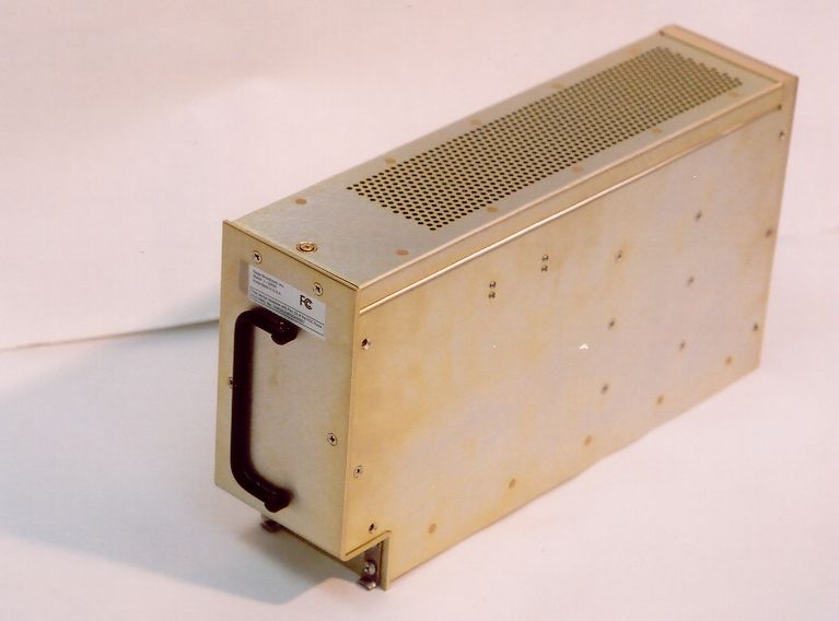
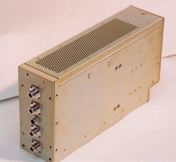
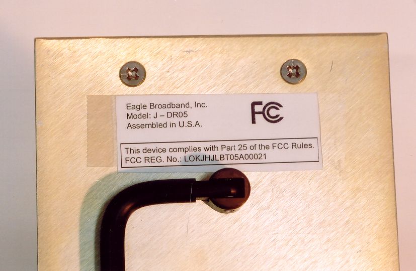
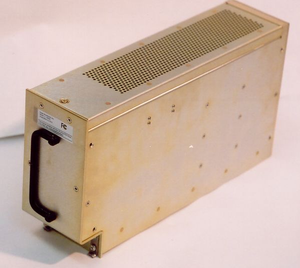
LOKJHJLBT05A00021Iridium Repeater
Universal Repeater, LLC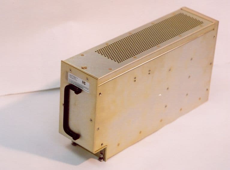
Click to zoom
Application Details
- Equipment Class
- AMP - Amplifier
- Date of Grant
- Oct 24, 2003
- Application Purpose
- Original Equipment
- Date of Application
- Oct 24, 2003
- Equipment Note
- Iridium Repeater
- Frequency Range
- 1616.00000000 - 1626.50000000
- Company
- Universal Repeater, LLC
- Country
- United States
Documents & Files
Document Text
Text extracted from the exhibit documents filed with the FCC. Open a document above to read the original.
Cover Letter(s)
WAYNE LANGSTON, INC. P.O. Box 1377, League City, TX 77574-1377 Phone: 281-337-6785; Fax: 281-337-7217; Email: [email protected] www.waynelangstoninc.com October 22, 2003 Confidentiality Request Letter FCC ID: LOKJHJLBT05A00021 Applicant: Eagle Wireless International, Inc. RE: Request of Confidentiality As agent for and on behalf of Eagle Wireless International, Inc., and Pursuant to Sections 0.457(d)(1)(ii) and 0.459 of the Commission’s Rules, the applicant hereby requests confidential treatment of information accompanying as outlined below: Identification of the specific information for which confidential treatment is sought: Block Diagram Schematics Parts List If you should have further questions or problems with this request, please contact me at (office 281-337- 6785 or Cell: 281-731-4895). Respectfully, Wayne Langston Agent
Cover Letter(s)
Iridium Satellite LLC 8440 South River Parkway Tempe, Arizona 85284 USA T: +1.480.752.1100 F: +1.480.752.1105 October 22, 2003 Mr. Jon Hayden Eagle Broadband 101 Courageous Drive League City, TX 77573 Reference: Value Added Manufacturer Agreement between Iridium Satellite LLC and Eagle Broadband, dated June 17 th , 2003 Subject: VAM Product Certification Based upon VAM’s fulfillment of all requirements as specified in Exhibit B of the referenced Agreement (including any such requirements as waived by LLC), LLC hereby certifies the following Product(s) for commercial use, subject to obtaining FCC certifications and limited to three (3) simultaneous voice calls, in connection with the Iridium Communications System: • Iridium Repeater Model J-DR05 V2.1 for use with Iridium phone operation indoors In the event that a significant Product defect (including a significant network or system defect which can reasonably be attributed to the Product) is identified subsequent to LLC’s issuance of this certification, LLC reserves the right to withdraw this certification letter at any time. VAM shall cooperate with LLC in compliance with Exhibit B as necessary for LLC to evaluate the defect and to re-issue such Product certification. Should you have any questions regarding this Product certification, please contact the undersigned at 703-724-8033. Sincerely, Drew Uplinger Director, VAM Program
Cover Letter(s)
American Telecommunications Certification Body Inc. 6731 Whittier Ave, McLean, VA 22101 October 24, 2003 RE: FCC ID: LOKJHJLBT05A00021_ATCB000871 Attention: Wayne Langston I have a few comments on this Application. 1. FYI – The 731 says this is a TNF (held to the face). However, from our discussions it appears that this is an amplifier. This would be equipment code “AMP”. Please clarify. 2. Please provide the schematics for the device. 3. Please provide the manual of user information provided with the device. The user information should contain all of the rf exposure information and other cautions pertinent to this device. 4. Please provide a short operational description of the device. What is it, etc. 5. Please provide the test report for the device showing compliance to part 25 subparts C and D (as needed). 6. Please show photos of the internal components of the device. The photos provided only show the outside of certain parts of the device but do not show component layout or circuit boards. 7. Please provide MPE information for the device. Dennis Ward mailto:[email protected] The items indicated above must be submitted before processing can continue on the above referenced application. Failure to provide the requested information may result in application termination. Correspondence should be considered part of the permanent submission and may be viewed from the Internet after a Grant of Equipment Authorization is issued. Please do not respond to this correspondence using the email reply button. In order for your response to be processed expeditiously, you must submit your documents through the AmericanTCB.com website. Also, please note that partial responses increase processing time and should not be submitted. Any questions about the content of this correspondence should be directed to the sender.
Operational Description
FCC STATEMENT This device complies with Part 15 of the FCC Rules. Operations is subject to the following two conditions: (1) This device may not cause harmful interference, and 2) this device must accept any interference received, including interference that may cause undesired operation CAUTION Any changes or modifications not expressly approved by the manufacturer responsible for compliance could void the user’s authority to operate the equipment.
RF Exposure Info
1.1 Indoor RF Safety Measurements In order to determine compliance with accepted standards at the TSC, RF safety measurements were taken at the beginning of the testing. The following description provides the results of this activity. The maximum permissible exposure limit for RF radiation, as recommended by ANSI, and adopted by Boeing, is that the power density shall not exceed 1 mw/cm^2 (one milliwatt per square centimeter) for an exposure time of 6 minutes. To determine max power density limits for longer exposure time, reference is made to Fig 5.0-3 of document titled " RF Power Density Measurements At The TSC Facility For Certification Of A Radiation Hazard Free Environment " dated 7-19-02. To verify that no radiation hazard exists for personnel working in the area during evaluation testing of Eagle's repeater system, two different measurement methods were used. They are an indirect measurement, and a direct measurement. a) Indirect Method: For the indirect measurement method, the power into the ceiling down-link Tx antenna (this is the antenna that radiates RF energy into the area in question) was measured with a spectrum analyzer, and was found to be about 0 dBm or 1 milliwatt of burst peak power. The ceiling antenna is a hemispherical omni antenna with a typical nominal gain of 0 dBic. This equates to an effective aperture of about 0.0032 square meters at the Iridium frequency band of 1616 to 1626.5 MHz. Using these parameters the calculation for power density indicates a value of 0.03125 mw/cm^2 at the antenna far field distance of 0.035 meters. The power density then decreases at the rate of 6 db / octave of distance. The conclusion arrived at from this measurement is that the power density level is well below the recommended max exposure limits as set forth by the ANSI standard. b) Direct Method: The direct method for power density measurement utilizes the Narda Measurement System Equipment. This equipment consists of a Model: 495 hand held meter, along with a Model-95 Hand held RF probe, which have been calibrated by a certified standards lab. The most sensitive full scale reading of the meter is 1 mw/cm^2, with three major divisions and 20 minor divisions equal to 0.05 mw/cm^2. When the probe was held approximately 1 meter from the ceiling antenna the meter indicated a reading of less than 1 minor division, or 0.05 mw/cm^2. Again the conclusion arrived at from this measurement is that the power density level is well below the recommended maximum exposure limits as set forth by the ANSI standards. Since the power density levels obtained from the two measurement methods are comparable in value it can be stated with a high level of confidence that personnel working in the immediate area of the radiating antenna are not being (or have not been) exposed to hazardous RF radiation levels, even when working there for several hours at a time. However it should be noted that according to OSHA rules, all personnel in an RF controlled area must be made aware of the possible health risk associated with the RF radiation they are being exposed to.
Test Report
WAYNE LANGSTON, INC. Model: J-DR05 FCC ID: LOKJHJLBT05A00021 Date: 10-22-2003 Number of Pages: 10 WLI Project: 20031846 FCC TEST/MEASUREMENT REPORT Product Name: J-DR05 Model: J-DR05 Applicant/Manufacturer: EAGLE WIRELESS INTERNATIONAL, INC. 101 Courageous Drive League City, Texas 77573 Tested By Request of: Eagle Wireless International, Inc. Testing Laboratory: Wayne Langston, Inc. P.O. Box 1377, League City, Texas 77574-1377 Tel: 281-337-6785; Fax: 281-337-7217; email: [email protected] Test Results: I certify that I am the technically qualified person responsible for preparation of the technical information contained in this application, and that it is complete and accurate to the best of my knowledge. Tested By: Date: October 22, 2003 Wayne Langston Incorporated authorizes the above-named Applicant company to reproduce this Report provided it is reproduced in its entirety. THIS REPORT MUST NOT BE USED TO CLAIM PRODUCT ENDORSEMENT BY NVLAP OR ANY AGENCY OF THE U.S. GOVERNMENT WAYNE LANGSTON, INC. Model: J-DR05 FCC ID: LOKJHJLBT05A00021 Date: 10-22-2003 Page i of 10 WLI Project: 20031846 TABLE OF CONTENTS 1. Introduction 1.1 Test Facility 1.2 Test Samples 1.3 Test Results 2. Information required for Type Acceptance/Certification 2 1033 FCC Form 731 2.1033(a) Applicant/Manufacturer 2.1033(2) Equipment identification 2.1033(3) Operations/Installation Manual 2.1033(10) Circuit Diagram 2.1033(11) Label Drawing 2.1033)12) Photographs Part 25 Satellite Communications 6.0 Introduction 6.0.1 Product Description 6.1.2 Requirements 6.1.3 Operational Configuration 6.1.4 Measurement Equipment 6.1.5 Radiated Spurious Emissions Procedure 6.1.6 Conducted Spurious Emissions Procedure 6.2 Test Results 6.2.1 RF Power Output Data 6.2.2 Radiated Spurious Emissions Measurement Test Results 6.2.3 Conducted Spurious Emissions Measurement Test Results 6.2.4 Frequency Stability Measurement Test Results WAYNE LANGSTON, INC. Model: J-DR05 FCC ID: LOKJHJLBT05A00021 Date: 10-22-2003 Page 1 of 10 WLI Project: 20031846 1. INTRODUCTION The following data has been taken in support of an Application for Type Acceptance for the Eagle Wireless International Iradium Repeater (FCC ID LOKJHJLBT05A00021) in accordance with Part 25. 1.1 Test Facility: Noted and Complies. This test site is located adjacent to the building in League City, Texas, 77573. All equipment is calibrated thru primary standards. Calibration period is 1 year and is accomplished in August of each year any alterations to this schedule is noted in the test data. Wayne Langston, Inc. has received NVLAP Accreditation, Certificate No. 200021-0. 1.2 Test Samples: A representative sample of the Equipment Under Test (EUT), was tested and the test results for this sample provided are located in the Appendix. 1.3 Test Results: The results from this testing apply only to the sample that was tested. The findings do not make any suggestions about how the product is to be used nor does Wayne Langston, Incorporated make any recommendations regarding the product's usage. 2. INFORMATION REQUIRED FOR TYPE ACDEPTANCE / CERTIFICATION PER PART 2 WAYNE LANGSTON, INC. Model: J-DR05 FCC ID: LOKJHJLBT05A00021 Date: 10-22-2003 Page 2 of 10 WLI Project: 20031846 Paragraphs 2.1033(a) A completed FCC Form 731 is included with this application. 2.1033(1) Applicant/Vendor/Manufacturer: Eagle Wireless International, Inc. 101 Courageous Drive League City, Texas 77573 2.1033(2) This equipment is identified as the Iradium Repeater FCC ID: LOKJHJLBT05A00021 2.1033(3) Installation manual is not available to the user. 2.1033(4) The circuit functions are described in the Appendix. 2.1033(10) Complete circuit diagram is attached to this application. 2.1033(11) Label drawing and label placement are provided with this application 2.1033(12) Photographs are included with this application. Part 25 Satellite Communications 6.0 Introduction 6.0.1 Product Description The Eagle Iridium L-Band Repeater unit (ILR) is a uplink and downlink repeater designed to be used in conjunction with the Iridium Subscriber System operating under the frequency constraints outlined in CFR 25.20R(4): this repeater provides signal downlink and uplink in obstructed areas. WAYNE LANGSTON, INC. Model: J-DR05 FCC ID: LOKJHJLBT05A00021 Date: 10-22-2003 Page 3 of 10 WLI Project: 20031846 These satellite phones consist of an L-Bank Transceiver (LBT) capable of simultaneous transmit and receive (duplex) operation covering the frequency range of 1616 MHz to 1626.5 MHz. The frequency accesses used for duplex channels are organized into sub- bands each of which contains eight frequency accesses. Each sub-band, therefore, occupies 333.33 kHz (i.e. 8 s 41.667 kHz). Up to 30 sub-bands containing 240 frequency accesses may be used for duplex channels. 6.1.1 Requirements The Sebring is subject to FCC Part 25, Subpart C and Part 2 for FCC Certification for units marketed within the United States. The following tests, as specified in FCC Part 2, with limits as defined in FCC Part 25, and shown were performed on the Mobile Iridium Subscriber Unit (ISU). Frequency allocation is defined under 25.202(4)i. WAYNE LANGSTON, INC. Model: J-DR05 FCC ID: LOKJHJLBT05A00021 Date: 10-22-2003 Page 4 of 10 WLI Project: 20031846 Test Parameter FCC Part 2 Paragraph Number FCC Part 25 Paragraph Number FCC Part 25 Limit Spectrum Mask 25.202 Frequency Offset Atten 20.833-41.667 25 dBc 41.667-104.16 kHz 35 dBc >104.67 kHz 43+10 log (Pt) Spurious Emissions Antenna Terminals 2.1051 25.202 25.213 Same as above Radiated Spurious Emissions 2.1053 “ “ Carrier Frequency Stability- Temperature * 2.1055 25.202 0.001% Carrier Frequency Stability-Voltage * 2.1055 25.202 0.001% * As the EUT, Eagle Iridium L-Bank Repeater is a amplifier-noted filter only carrier frequency shifts is determined for the source handset, the unit may not perform. 6.1.2 Operational Configuration The ILR EUT was operated in transmit mode at maximum rated output power of 5 Watts (+37 dBm) for upl…
Text truncated - open the document above for the full version.
Contact Information
Applicant
F. Scott Yeager(President)
Technical Contact
Wayne Langston, Inc.Wayne Langston
[email protected]281-337-6785
P.O. Box 1377 · League City, Texas · United States
Technical Specifications
| # | Rule Parts | Frequency Range | Power Output | Emission |
|---|---|---|---|---|
| 2 | 25 | 1.62 GHz - 1.63 GHz | 100.00 mW | AMP |
Other Applications from Universal Repeater, LLC

LOK150-TX-UHS-2
Nov 10, 2004Extend-A-Page
Equipment Class
TNB - Licensed Non-Broadcast Station Transmitter
LOK450-PA-2
Aug 16, 2001Amplifier
Equipment Class
TNB - Licensed Non-Broadcast Station TransmitterLOK72-TX
Feb 16, 1998TNB - Licensed Non-Broadcast Station Transmitter
Equipment Class
TNB - Licensed Non-Broadcast Station TransmitterLOK070-RX-1
Oct 20, 1997CXX - Communications Rcvr for use w/ licensed Tx and CBs
Equipment Class
CXX - Communications Rcvr for use w/ licensed Tx and CBsLOK900-PA-3
Sep 30, 1997Input Drive Level 2W
Equipment Class
TNB - Licensed Non-Broadcast Station Transmitter