LOK450-PA-2Amplifier
Universal Repeater, LLC
Click to zoom
Application Details
- Equipment Class
- TNB - Licensed Non-Broadcast Station Transmitter
- Date of Grant
- Aug 16, 2001
- Application Purpose
- Original Equipment
- Date of Application
- Aug 16, 2001
- Equipment Note
- Amplifier
- Frequency Range
- 450.00000000 - 470.00000000
- Company
- Universal Repeater, LLC
- Country
- United States
Documents & Files
Document Text
Text extracted from the exhibit documents filed with the FCC. Open a document above to read the original.
Users Manual
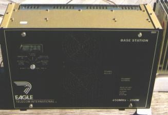
UHF 250 WATT POWER AMPLIFIER USER Manual EAGLE WIRELESS INTERNATIONAL 101 Courageous Drive League City, TX 77573 Telephone: (281) 538-6000 Fax: (281) 334-5302 Toll Free: 1-800-628-3910 www.eglw.com [email protected] Preface Preface Scope This user manual contains a high level description of the UHF 250 Watt Power Amplifier as well as a detailed technical description. The scope of this document is to provide the reader with a general understanding, system description, and operation of the UHF 250 Watt Power Amplifier. Section 1 – Presents a general introduction of the UHF 250 Watt Power Amplifier who are familiarizing themselves with the system for the first time. Section 2 – Highlights the major features and specifications of the power amplifier. Section 3 – Outlines the major system components. Section 5 – Appendices and Schematics. Copyright This document contains proprietary information protected by copyright. All rights reserved. No part of this document may be photocopied, reproduced, transmitted, transcribed, stored in a retrieval system, or translated into any language in any form by any means, electronic, mechanical, magnetic, optical, chemical, hydraulic, manual or otherwise without prior written consent of EAGLE WIRELESS INTERNATIONAL, INC. EAGLE WIRELESS INTERNATIONAL, INC. software and firmware programs used in the UHF 250 WATT POWER AMPLIFIER is protected by copyright. Therefore, no software or firmware may be copied or reproduced in any manner written consent of EAGLE WIRELESS INTERNATIONAL, INC. Notice Some EAGLE WIRELESS INTERNATIONAL products may be labeled Eagle Telecom International. These are simply trade names for certain EAGLE product lines. EAGLE WIRELESS INTERNATIONAL, INC. provides this publication as is with no warranty of any kind, either express or implied including, but not limited to the implied warranties of merchantability or fitness for a particular purpose. Some states do not allow disclaimer or express or implied warranties in certain transactions; therefore, this statement may not apply in all instances. Version 3 i 07/18/01 Preface This publication may have technical inaccuracies or typographical errors. Therefore, the information contained in this manual is subject to change or revision. Changes or revisions will be incorporated in all new editions of the publication. EAGLE WIRELESS INTERNATIONAL, INC. may at any time make improvements and/or changes in product(s) and/or program(s) described in this publication. Products are stocked at the address below. Requests for copies of this publication and for technical information should be directed to EAGLE WIRELESS INTERNATIONAL, INC. Customer Service Eagle Wireless International’s Customer Service Department is dedicated to provide complete product support to all its customers. For Technical Assistance only, call the toll-free number 1-800-628-3910, between the hours of 8:00 A.M. and 5:00 P.M. (CST). For after hours emergencies, call (281) 538-6000 for instructions. If you reach voice mail, please leave a message and your call will be returned promptly. Customers should maintain a stock of replacement parts or units for emergency backup. Eagle Wireless International’s factory trained field service engineers are available for system installation and optimization. For assistance, write or call: EAGLE WIRELESS INTERNATIONAL, INC. 101 Courageous Drive, League City, TX 77573 Telephone (281) 538-6000 Fax (281) 334-5302 Toll Free 1-800-628-3910 Version 3 ii 07/18/01 Preface Cautions & Safety Regulations All RF power transistor and RF termination resistors in this power amplifier contain the toxic substance beryllium oxide. These assemblies are located on the combiner, splitter and power amplifier boards. The fumes and dust of beryllium oxide is also toxic and should only be treated by trained personnel using proper precautions. Federal law and most state laws strictly prohibit disposal of beryllium oxide as a public waste. FCC Requirements FCC regulations state that: 1. Radio transmitters may be tuned or adjusted only by persons holding a general class commercial radiotelephone operator’s license, a registered engineer or by personnel working under their immediate supervision. 2. The RF power output of a radio transmitter shall be no more than that required for satisfactory technical operation considering the area to be covered and local conditions. 3. The frequency, deviation, and power of a base station transmitter must be maintained within specified limits. It is recommended, therefor, that these three parameters be checked before the station is placed in service. 4. The power input to the final radio frequency stage shall not exceed the maximum figure specified on the current station authorization. This power input shall be measured and the results recorded: a. When the transmitter is initially installed. b. When any change is made in the transmitter, which may increase the power input. c. At intervals not to exceed on year. FCC Interference Warning FCC regulations state that: This equipment generates, uses, and can radiate radio frequency energy and if not installed and used in accordance with the instructions manual, may cause interference to radio communications. As temporarily permitted by regulation it has not been tested for compliance with the limits for Class A computing devices pursuant to Sub-part J of Part 15 of FCC Rules, which are designed to provide reasonable protection against such interference. Operation of this equipment in a residential area is likely to cause interference in which case the user at his own Version 3 iii 07/18/01 Preface expense will be required to take whatever measures may be required to correct the interference. OSHA Safety Standards The United States Department of Labor, through the provisions of the Occupational Safety and Health Act, has established an electromagnetic energy safety standard with applies to the use of this equipment. Proper use of this radio equipment wil…
Text truncated - open the document above for the full version.
Cover Letter(s)
American Telecommunications Certification Body Inc. 6731 Whittier Ave, McLean, VA 22101 June 20, 2001 RE: Eagle Wireless FCC ID: LOK450PA-2 I have the following comments about this Application. Please address 1.) No manual was received. A copy of either the owner’s manual and/or installation manual must be submitted. See 2.1033(c)(3) 2.) Internal and External photographs must be submitted as separate exhibits. Inside photographs must also show both sides of printed wiring boards. Please submit one to a page and follow the guidelines of 2.1033(c)(12) 3.) Please supply a parts list. This can be held confidential if listed on Request for Confidentiality letter. There are no extra fees for Confidentiality. 4.) There are a multitude of plots in *.jpg format uploaded to the RF Exposure Information exhibit. I would be berated repeatably with a wet noodle if I uploaded all the plots this way. Please combine into a single document. I recommend inserting into a Word document and then converting to *.pdf format. This document should then be uploaded to the TEST REPORT exhibit. 5.) Can this device operate over a range of output power levels? If so, it should be stated on Form 731. 6.) Please extract and provide Operational Description of all devices that suppress spurious radiation and limit power per 2.1033(c)(10) 7.) Will the Ritron DTX454 be the only exciter used with this device? 8.) All label and label placement should be submitted as a separate exhibit. Please extract from your test report. 9.) Proposed Grant notes: • “Power Output listed is Conducted. The antenna(s) used for this transmitter must be fixed-mounted on outdoor permanent structures. RF exposure compliance is addressed at the time of licensing, as required by the responsible FCC Bureau(s), including antenna co-location requirements of §1.1307(b)(3). Approved for use with Ritron DTX454 only” William H. Graff Examining Engineer President and Director of Engineering mailto:[email protected] The items indicated above must be submitted before processing can continue on the above referenced application. Failure to provide the requested information may result in application termination. Correspondence should be considered part of the permanent submission and may be viewed from the Internet after a Grant of Equipment Authorization is issued. Please do not respond to this correspondence using the email reply button. In order for your response to be processed expeditiously, you must submit your documents through the AmericanTCB.com website. Also, please note that partial responses increase processing time and should not be submitted. Any questions about the content of this correspondence should be directed to the sender.
Test Report
WAYNE LANGSTON, INC. Model: UPT-250 FCC ID: LOK450-PA-2 Date: 06-05-2001 Number of Pages: 10 WLI Project: 20011745 FCC TYPE ACCEPTANCE TEST/MEASUREMENT REPORT Product Name: 450 MHz Transmitter Model: UPT-250 Applicant/Manufacturer: EAGLE WIRELESS INTERNATIONAL, INC. 101 Courageous Drive League City, Texas 77573 Tested By Request of: Eagle Wireless International, Inc. Testing Laboratory: Wayne Langston, Inc. P.O. Box 1377, League City, Texas 77574-1377 Tel: 281-337-6785; Fax: 281-337-7217; email: [email protected] Test Results: I certify that I am the technically qualified person responsible for preparation of the technical information contained in this application, and that it is complete and accurate to the best of my knowledge. Tested By: Wayne Langston Date: 06-05-2001 Wayne Langston Incorporated authorizes the above-named Applicant company to reproduce this Report provided it is reproduced in its entirety. THIS REPORT MUST NOT BE USED TO CLAIM PRODUCT ENDORSEMENT BY NVLAP OR ANY AGENCY OF THE U.S. GOVERNMENT WAYNE LANGSTON, INC. Model: UPT-250 FCC ID: LOK450-PA-2 Date: 06-05-2001 Page i of 10 WLI Project: 20011745 TABLE OF CONTENTS 1. Introduction 1.1 Test Facility 1.2 Test Samples 1.3 Test Results 2. Information required for Type Acceptance/Certification 2 1033 FCC Form 7310 2.1033(a) Applicant/Manufacturer 2.1033(2) Equipment identification 2.1033(3) Operations/Installation Manual 2.1033(4) Type of Emission 2.1033(5) Frequency Range 2.1033(6) Range of Operating Power Level 2.1033(7) Maximum power rating 2.1033(8) Voltages/Current applied 2.1033(9) Tune-up Procedure 2.1033(10) Circuit Diagram 2.1033(11) Equipment I/O 2.1033)14) Measurement Data 2.1046 Measurements required: RF Power Output 2.1047 Modulation Characteristics 2.1049 Occupied Bandwidth 2.1051 Spurious emissions at antenna terminals 2.1053 Field Strength of Spurious Radiation 2.1055 Frequency Stability WAYNE LANGSTON, INC. Model: UPT-250 FCC ID: LOK450-PA-2 Date: 06-05-2001 Page 1 of 10 WLI Project: 20011745 1. INTRODUCTION The following data has been taken in support of an Application for Type Acceptance for the Eagle Wireless International RF Power Amplifier (FCC ID: LOK450-PA-2) in accordance with Part 2, Subpart J, Part 90 of the Federal Communications Rules and Regulations. Under Part 90, 635 the maximum power allowable is 500 watts which is well over The PA available power of 250 watts. The equipment under test (EUT) is a 460 MHz Power Amplifier, which operates between 450-470 MHz. These bands are licensed under Part 90. This particular unit is capable of digital and audio and an exciter capable of both was used for the tests. Bands 450-470 are covered under Part 90 per clause 90.205 thru 90.214. 1.1 Test Facility: Noted and Complies. This test site is located adjacent to the building in League City, Texas, 77573. All equipment is calibrated and traceable to NIST thru primary standards. Calibration period is 1 year and is accomplished in August of each year any alterations to this schedule is noted in the test data. Wayne Langston, Inc. has received NVLAP Accreditation, Certificate No. 200021-0. 1.2 Test Samples: A representative sample of the Equipment Under Test (EUT), was tested and the test results for this sample provided are located in the Appendix. 1.3 Test Results: WAYNE LANGSTON, INC. Model: UPT-250 FCC ID: LOK450-PA-2 Date: 06-05-2001 Page 2 of 10 WLI Project: 20011745 The results from this testing apply only to the sample that was tested. The findings do not make any suggestions about how the product is to be used nor does Wayne Langston, Incorporated make any recommendations regarding the product's usage. 2. INFORMATION REQUIRED FOR TYPE ACDEPTANCE / CERTIFICATION PER PART 2 Paragraphs 2.1033(a) A completed FCC Form 731 is included with this application. 2.1033(1) Applicant/Vendor/Manufacturer: Eagle Wireless International, Inc. 101 Courageous Drive League City, Texas 77573 2.1033(2) This equipment is identified as the Eagle Power Transmitter FCC ID: LOK450-PA-2 2.1033(3) Installation manual is not available to the user. 2.1033(4) The circuit functions are described in the Appendix. 2.1033(5) The frequency range of the amplifier is 450-470 MHz and the range of the exciter is controlled to within the allowable FCC limits 2.1033(6) The output power level is watts (53. dBm) . This amplifier has an output power range of 250 Watts. The output power is factory set at the maximum level of 250 Watts. Although the unit is intended to be operated at its maximum output power of 250 Watts. It does include a safety feature WAYNE LANGSTON, INC. Model: UPT-250 FCC ID: LOK450-PA-2 Date: 06-05-2001 Page 3 of 10 WLI Project: 20011745 which will allow the user to lower the output power during extreme conditions in order to protect the unit. This function is intended to be used as a safety device only. 2.1033(7)) The maximum rated power of 250 watts (+ 53. dBm). 2.1033(8) The DC hookup voltage is +27 volts with a range of +26 volts to +28 volts. Each of the 4 FET finals draws approximately seven amps with a drain to source voltage of 27 volts. The function of the special IC’s and components are as follows: a). The Pre-Amp is capable of a variable RF output with voltage variations. b). Each final is capable of approximately 90 Watts. c). the low pass filter reduces the harmonics to meet the FCC limits. 2.1033(9) All tune-up procedures are made at the factory. There are no power adjustments made during the installation of the equipment. 2.1033(10) Complete circuit diagram is attached to this application. 2.1033(11) Exhibit 1 is a label drawing and label placement. 2.1033(12) Photographs are included in the exhibit section. 2.1033(13) N/A 2.1033(14) The data required by Paragraph 2.1046 through 2.1057 are included with this report. 3, MEASUREMENT REQUIREMENTS (Paragraphs 2.985 et.seq) WAYNE LANGSTON, INC. Model: UPT-250 FCC ID: LOK450-PA-2 Date: 06-05-2001 Page 4 of 10 WLI Project: 20011745 This section contains the results…
Text truncated - open the document above for the full version.
Test Report
C:\ATCB Local Download\LOK450-PA-2\Test_Report_Plots\Occupied_BW_Plots.doc P age 1 C:\ATCB Local Download\LOK450-PA-2\Test_Report_Plots\Occupied_B W _ Plots.doc P age 2 C:\ATCB Local Download\LOK450-PA-2\Test_Report_Plots\Occupied_B W _ Plots.doc P age 3 C:\ATCB Local Download\LOK450-PA-2\Test_Report_Plots\Occupied_B W _ Plots.doc P age 4 C:\ATCB Local Download\LOK450-PA-2\Test_Report_Plots\Occupied_B W _ Plots.doc P age 5 C:\ATCB Local Download\LOK450-PA-2\Test_Report_Plots\Occupied_B W _ Plots.doc P age 6 C:\ATCB Local Download\LOK450-PA-2\Test_Report_Plots\Occupied_B W _ Plots.doc P age 7 C:\ATCB Local Download\LOK450-PA-2\Test_Report_Plots\Occupied_B W _ Plots.doc P age 8 C:\ATCB Local Download\LOK450-PA-2\Test_Report_Plots\Occupied_B W _ Plots.doc P age 9 C:\ATCB Local Download\LOK450-PA-2\Test_Report_Plots\Occupied_B W _ Plots.doc P age 10 C:\ATCB Local Download\LOK450-PA-2\Test_Report_Plots\Occupied_B W _ Plots.doc P age 11 C:\ATCB Local Download\LOK450-PA-2\Test_Report_Plots\Occupied_B W _ Plots.doc P age 12 C:\ATCB Local Download\LOK450-PA-2\Test_Report_Plots\Occupied_B W _ Plots.doc P age 13 C:\ATCB Local Download\LOK450-PA-2\Test_Report_Plots\Occupied_B W _ Plots.doc P age 14 C:\ATCB Local Download\LOK450-PA-2\Test_Report_Plots\Occupied_B W _ Plots.doc P age 15 C:\ATCB Local Download\LOK450-PA-2\Test_Report_Plots\Occupied_B W _ Plots.doc P age 16 C:\ATCB Local Download\LOK450-PA-2\Test_Report_Plots\Occupied_B W _ Plots.doc P age 17 C:\ATCB Local Download\LOK450-PA-2\Test_Report_Plots\Occupied_B W _ Plots.doc P age 18 C:\ATCB Local Download\LOK450-PA-2\Test_Report_Plots\Occupied_B W _ Plots.doc P age 19 C:\ATCB Local Download\LOK450-PA-2\Test_Report_Plots\Occupied_B W _ Plots.doc P age 20
Contact Information
Applicant
F. Scott Yeager(President)
Technical Contact
Eagle Wireless InternationalTapan K Adhikary
[email protected]281-538-6000
101 Courageous Drive · League City, Texas · United States
Non-Technical Contact
Wayne Langston IncWayne Langston
[email protected]281-337-6785
Test Firm
Wayne Langston, Inc.Wayne Langston
Technical Specifications
| # | Rule Parts | Frequency Range | Power Output | Emission | Tolerance |
|---|---|---|---|---|---|
| 3 | 9 | 450 MHz - 470 MHz | 250 W | F3D | 1.5 ppm |
Other Applications from Universal Repeater, LLC

LOK150-TX-UHS-2
Nov 10, 2004Extend-A-Page
Equipment Class
TNB - Licensed Non-Broadcast Station Transmitter
LOKJHJLBT05A00021
Oct 24, 2003Iridium Repeater
Equipment Class
AMP - AmplifierLOK72-TX
Feb 16, 1998TNB - Licensed Non-Broadcast Station Transmitter
Equipment Class
TNB - Licensed Non-Broadcast Station TransmitterLOK070-RX-1
Oct 20, 1997CXX - Communications Rcvr for use w/ licensed Tx and CBs
Equipment Class
CXX - Communications Rcvr for use w/ licensed Tx and CBsLOK900-PA-3
Sep 30, 1997Input Drive Level 2W
Equipment Class
TNB - Licensed Non-Broadcast Station Transmitter