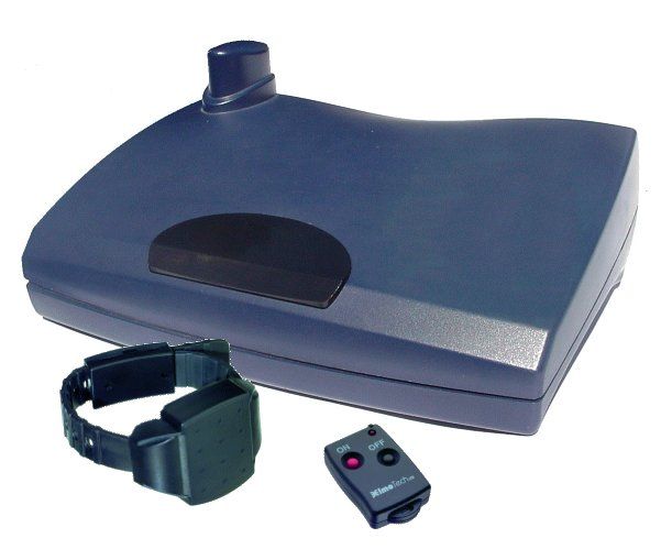
LSQ-DCU-2010Data collection unit, DCU 2010
Attenti
Click to zoom
Application Details
- Equipment Class
- CYY - Communications Receiver used w/Pt 15 Transmitter
- Date of Grant
- Jul 29, 2003
- Application Purpose
- Original Equipment
- Date of Application
- Jul 27, 2003
- Equipment Note
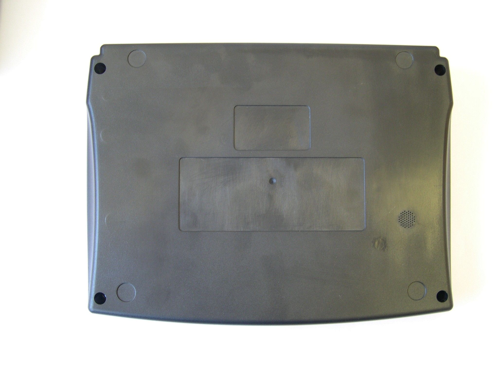
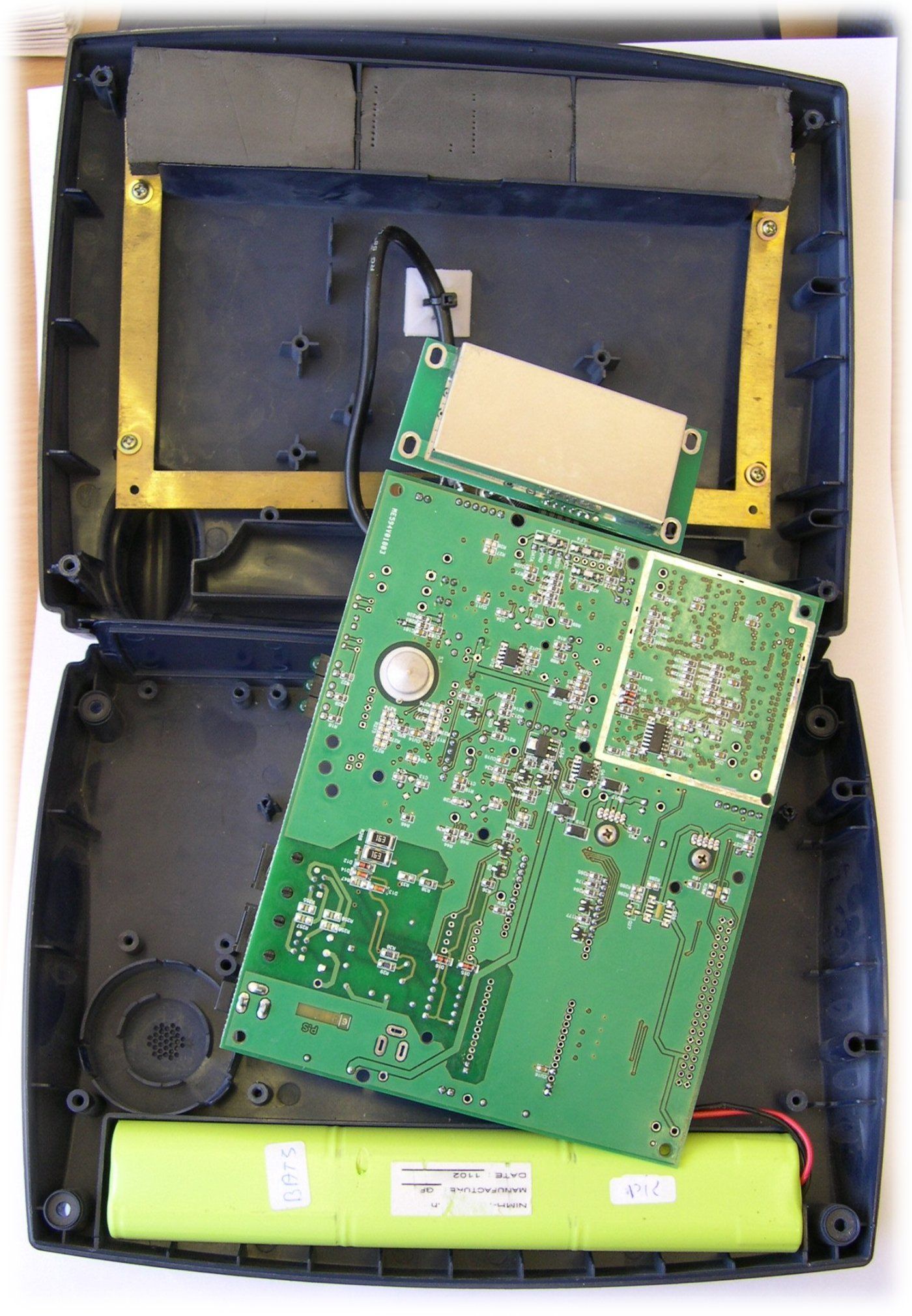
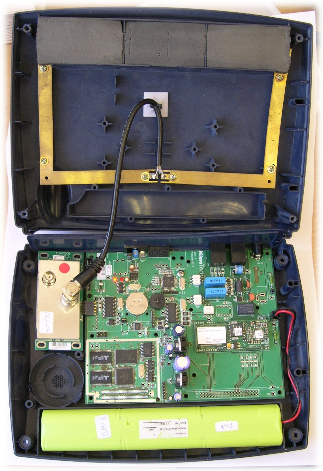
- Data collection unit, DCU 2010
- Frequency Range
- 318.00000000 - 318.00000000
- Company
- Attenti
- Country
- Israel
Documents & Files
Document Text
Text extracted from the exhibit documents filed with the FCC. Open a document above to read the original.
Users Manual
DCU 2010 INSTALLLATION MANUAL Version 1.0 April 2002 ElmoTech Ltd Version 1.0 DCU & Transmitter Field Installation Manual 1 Prepared by: Elmo-Tech Ltd. Corporate Headquarters 2 Ha-Barzel St. P.O. Box 13236 Ramat Ha-Chayal 61132 Tel Aviv Israel Tel: 03 – 6478871 Fax: 03 – 6478872 Visit us at: www.elmotech.com © 2002, Elmo Tech Ltd. All rights reserved. No part of this publication may be reproduced, stored in a retrieval system, or transmitted in any form or by any means, electronic, mechanical, photocopying, recording or otherwise, for purpose other than the user’s manual, without prior permission of Elmo Tech Ltd. NO WARRANTY The technical documentation is being delivered AS-IS, and ElmoTech Ltd. makes no warranty as to its accuracy or use. Any use of the technical documentation or the information contained therein is at risk of the user. Documentation may include technical or other inaccuracies or typographical errors. ElmoTech Ltd. Reserves the right to make change without prior notice. Version 1.0 ElmoTech Ltd DCU & Transmitter Field Installation Manual 2 ElmoTech Ltd Version 1.0 DCU & Transmitter Field Installation Manual 3 TABLE OF CONTENTS Section Page THE MONITOR CENTER/ PROBATION AGENCY.................. 7 EQUIPMENT....................................................................................... 8 THE OFFENDER’S PREMISES...................................................... 9 MONITORING SYSTEM LOCATION...................................................... 9 INSTALLING THE DCU UNIT............................................................ 10 Downloading the Curfew Schedule............................................ 12 I NSTALLING THE TRANSMITTER....................................................... 14 Calibrating the Transmitter........................................................ 14 Attaching the Transmitter........................................................... 16 DCU Range Setting.................................................................... 19 DAILY OPERATING INSTRUCTIONS....................................... 23 I NCOMING CALLS............................................................................ 23 Accepting an incoming call........................................................ 23 OUTGOING CALLS........................................................................... 24 Performing an outgoing call....................................................... 24 GENERAL RULES FOR THE OFFENDER.............................................. 25 REMOVING THE MONITORING SYSTEM.............................. 27 INITIATING AN END OF SERVICE...................................................... 27 D ISCONNECTING AND PACKING THE DCU UNIT.............................. 27 R EMOVING THE TRANSMITTER........................................................ 28 DISCONNECTING THE TRANSMITTER............................................... 29 Version 1.0 ElmoTech Ltd DCU & Transmitter Field Installation Manual 4 TRANSMITTER CLEANING INSTRUCTIONS ........................ 31 C LEANING THE TRANSMITTER:........................................................ 31 TRANSMITTER STRAP REPLACEMENT................................ 33 REASONS FOR STRAP REPLACEMENT............................................... 33 E QUIPMENT NEEDED FOR STRAP REPLACEMENT............................. 34 R EPLACING THE TRANSMITTER STRAPS........................................... 34 FCC NOTICES................................................................................. 36 DCU FCC NOTICES........................................................................ 36 DCU C USTOMER INFORMATION...................................................... 37 T RANSMITTER FCC NOTICES.......................................................... 39 ElmoTech Ltd Version 1.0 DCU & Transmitter Field Installation Manual 5 LIST OF FIGURES Figure Page F IGURE 1 IDEAL DCU LOCATION.......................................................... 9 F IGURE 2 DIAGRAMMATIC VIEW OF A DCU........................................ 11 F IGURE 3 CALIBRATING THE TRANSMITTER........................................ 15 F IGURE 4 ATTACHING THE TRANSMITTER........................................... 17 FIGURE 5 PROTRUDING SIDE OF TRANSMITTER DIRECTED UPWARDS... 17 F IGURE 6 MALE\FEMALE CLIPS ATTACHED........................................ 18 F IGURE 7 DISCONNECTING THE TRANSMITTER.................................... 29 Version 1.0 ElmoTech Ltd DCU & Transmitter Field Installation Manual 6 ElmoTech Ltd Version 1.0 THE MONITOR CENTER/ PROBATION AGENCY At the Monitor Center/Probation Agency: 1. Enter the Offender’s data in the monitoring application. This can be done well in advance, even before the actual equipment is allocated and installed. 2. Enter the following equipment data in the monitoring application. • DCU Serial No. - Check that the number entered matches the number on the DCU unit. • Transmitter Serial No. - Check that the number entered matches the number on the Transmitter. The DCU and Transmitter Serial numbers are visible on the back of each unit. DCU & Transmitter Field Installation Manual 7 Version 1.0 ElmoTech Ltd Equipment Check that you have all the required equipment: • DCU unit and power adapter • Transmitter • Electronic key • Locking device • Strap holder • Strap clips (male and female) • Screwdriver (to open a clip if necessary). It is recommended to use a 5 mm flat head screwdriver. It is always advisable to bring an extra set of strap clips to cater for the event in which the first set may be accidentally damaged during the installation. DCU & Transmitter Field Installation Manual 8 ElmoTech Ltd Version 1.0 THE OFFENDER’S PREMISES Monitoring System Location In order to install the Monitoring System, you will need to find the best location for the DCU unit. The ideal place for the DCU unit is in the center of the house, 3 feet off the ground and at least 1 foot away from the wall. Figure 1 Ideal DCU Location DCU & Transmitter Fi…
Text truncated - open the document above for the full version.
Block Diagram
DCU Block Diagram Figure no.1: Main Module Diagram CPU- RFMMITBD SCI INTERNAL MODEM LAN OR VMU POWER +BATTERY RAM + FLASH MEMOREY RS232 OR RS485 RESET ON POWER MANUAL RESET REAL TIME CLOCK UART A UART B BUILD IN SENSORS CPU INTERNAL BUS S/wr load control Elmo-Tech LTD Ver. 1.01 DCU_Block Diagram 1.1.1 COMMUNICATION OBJECTS Telephone. General purpose-s\w load. RF. Figure no.2: RF Object Diagram RF RF CPU RF RECIVER CPU INTERNAL BUS RSSI DATA Elmo-Tech LTD Ver. 1.01 DCU_Block Diagram LED’s internal and external. Buzzer & Siren Voice. Relay. Button’s Built in sensors. VOICE BUZZER LED LED LED CPU INTERNAL BUS Panic Button Download button Tilt &Case Open LED SIREN
Cover Letter(s)
TCB Confidentiality Form 20/07/2003 EMCCert DR. RAŠEK Boelwiese 5 91320 Ebermannstadt Germany Tel.: +49-9194-9331 Fax: +49-9194-7964-84 E-mail: [email protected] URL: http://www.emcc.de Gentlemen: This letter is to comply with Section 0.457(d)(2)(i) pertaining to confidential material. Elmo Tech would like the following document regarding this submission for FCC ID: LSQ-DCU-2010 to be kept confidential. Schematics: 1 Page. The above material contains trade secrets or technical data, which would customarily be guarded from competitors. We do not want this document to be accessible to the general public. Sincerely, Gil Gemer VP R&D
ID Label/Location Info
Label Location
Operational Description
ElmoTech Ltd Version 1.0 THE OFFENDER’S PREMISES Monitoring System Location In order to install the Monitoring System, you will need to find the best location for the DCU unit. The ideal place for the DCU unit is in the center of the house, 3 feet off the ground and at least 1 foot away from the wall. Figure 1 Ideal DCU Location DCU & Transmitter Field Installation Manual 9 Version 1.0 ElmoTech Ltd DCU & Transmitter Field Installation Manual 10 The DCU unit should be in an open area away from other electrical appliances (e.g. personal computers, laptops) or any metal objects. Installing the DCU Unit In order to install the DCU unit: 1. Plug the appropriate end of the power adapter cord into the 12VDC socket at the back of the DCU unit. 2. Plug the power adapter into a wall power socket. The DCU unit makes an audible beeping sound and then runs through a series of built-in-tests to check that everything is in order. 3. After completing the tests successfully the DCU unit beeps again and the two external LED’s, located at the rear of the DCU unit, are turned on. This indicates that the DCU unit is in working order. The LED indicators are: • Left LED - indicates that power is connected • Right LED - indicates that the DCU unit has registered to a telephone network (network registration may take up to one minute after built-in- test completion). ElmoTech Ltd Version 1.0 DCU & Transmitter Field Installation Manual 11 Figure 2 Diagrammatic View of a DCU If, at the end of the start-up self test, audible beeping sounds are heard and all three LED’s flash for 10 seconds, it indicates one of the following possible failures: i Case open micro-switch malfunction. i Tilt sensor malfunction. i Range threshold values lost (maximum reception range is used in this case).
Test Report
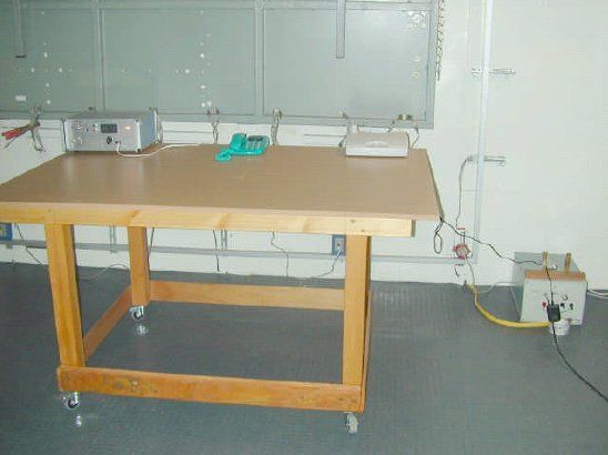
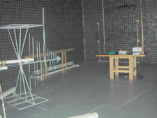
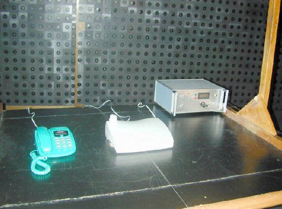
This report is in conformity with ISO/IEC 17025. The A2LA logo endorsement applies only to the test methods and the standards that are listed in the scope of Hermon Laboratories accreditation. The test results relate only to the items tested. This test report must not be reproduced in any form except in full with the approval of Hermon Laboratories Ltd. Page 1 of 25 Document ID: ELMEMC_FCC.14591.doc Date of Issue: September 2002 HERMON LABORATORIES Electrical Hermon Laboratories Ltd. P.O.Box 23 Binyamina 30550, Israel Tel.+972 46288001 Fax.+972 46288277 e-mail: [email protected] ELECTROMAGNETIC EMISSIONS TEST REPORT ACCORDING TO 47CFR PART 15 for ElmoTech Ltd. EQUIPMENT UNDER TEST: Data collection unit Model: DCU 2010 Page 2 of 25 Document ID: ELMEMC_FCC.14591.doc Date of Issue: September 2002 HERMON LABORATORIES Hermon Laboratories Ltd. P.O.Box 23 Binyamina 30550, Israel Tel.+972 46288001 Fax.+972 46288277 e-mail: [email protected] Description of equipment under test Test item Data collection unit Manufacturer ElmoTech Ltd. Type (Model) DCU 2010 Hardware version 1.4 Software release 1.50 Serial number 29010312 Receipt date March 20, 2001 Applicant information Applicant’s responsible person Mr. Alex Rachman, R&D Manager Company ElmoTech Ltd. P.O.Box 13236 Address 2 Habarzel street City Tel Aviv Postal code 61132 Country Israel Telephone number +972 36478871 Telefax number +972 36478872 Test performance Project number: 14591 Location Hermon Laboratories Test perfromed August 27, 2002 Purpose of test Apparatus compliance verification in accordance with emission requirements Test specification 47CFR part 15, subpart B, Class B Page 3 of 25 Document ID: ELMEMC_FCC.14591.doc Date of Issue: September 2002 HERMON LABORATORIES Hermon Laboratories Ltd. P.O.Box 23 Binyamina 30550, Israel Tel.+972 46288001 Fax.+972 46288277 e-mail: [email protected] 1 Summary and signatures The EUT was found complying with the limits of 47CFR part 15: 2001, subpart B, Class B. Standard ref. Report ref. Method Emissions limits Ports / enclosure tested Tested by Date tested P/F/NA/ NT 1 Rationale Emissions Mains terminal radio interference voltage measurements 47CFR part 15 Table 4.1.2 ANSI C63.4 Class B 120 V AC power Mrs. E. Pitt, test engineer August 27, 2002 P Radiated emission measurements 47CFR part 15 Table 4.2.2 ANSI C63.4 Class B Enclosure Mrs. E. Pitt, test engineer August 27, 2002 P Test report prepared by: Ms. N. Averin, certification engineer Test report approved by: Dr. E. Usoskin, C.E.O. 1 P = Pass, F = Fail, NA = Not applicable, NT = Not tested Page 4 of 25 Document ID: ELMEMC_FCC.14591.doc Date of Issue: September 2002 HERMON LABORATORIES Hermon Laboratories Ltd. P.O.Box 23 Binyamina 30550, Israel Tel.+972 46288001 Fax.+972 46288277 e-mail: [email protected] Contents 1 SUMMARY AND SIGNATURES......................................................................................................................................................3 2 GENERAL INFORMATION...............................................................................................................................................................5 2.1 ABBREVIATIONS AND ACRONYMS...................................................................................................................................................5 2.2 SPECIFICATION REFERENCES.........................................................................................................................................................5 2.3 EUT DESCRIPTION.........................................................................................................................................................................6 2.4 EUT TEST CONFIGURATION...........................................................................................................................................................6 3 TEST FACILITY DESCRIPTION......................................................................................................................................................8 3.1 GENERAL........................................................................................................................................................................................8 4 EMISSIONS TESTS............................................................................................................................................................................9 4.1 MAINS TERMINAL RADIO INTERFERENCE VOLTAGE MEASUREMENTS..............................................................................................9 4.2 RADIATED EMISSION MEASUREMENTS..........................................................................................................................................15 APPENDIX A – MEASUREMENT UNCERTAINTY, TEST EQUIPMENT AND ANCILLARIES USED FOR TESTS..............23 APPENDIX B - TEST EQUIPMENT CORRECTION FACTORS.......................................................................................................24 Page 5 of 25 Document ID: ELMEMC_FCC.14591.doc Date of Issue: September 2002 HERMON LABORATORIES Hermon Laboratories Ltd. P.O.Box 23 Binyamina 30550, Israel Tel.+972 46288001 Fax.+972 46288277 e-mail: [email protected] 2 General information 2.1 Abbreviations and acronyms The following abbreviations and acronyms are applicable to this test report: AC alternating current cm centimeter dB decibel dBm decibel referred to one milliwatt dB(μV) decibel referred to one microvolt dB(μV/m) decibel referred to one microvolt per meter DC direct current EMC electromagnetic compatibility EMI electromagnetic interference EUT equipment under test GHz gigahertz H height Hz hertz kHz kilohertz kV kilovolt L length LISN line impedance stabilization network m meter NA not applicable QP quasi-peak RF radio frequency RE radiated emission rms root mean square s second V volt W width 2.2 Specification references 47CFR part 15 subpart B: 2001 Radio Freque…
Text truncated - open the document above for the full version.
Contact Information
Applicant
Yossi Murciano(Quality Assurance Manager)
Test Firm
Hermon Laboratories Ltd.Alexander Usoskin
Technical Specifications
| # | Rule Parts | Frequency Range | Power Output |
|---|---|---|---|
| 1 | 15B | 318 MHz - 318 MHz | - |
Other Applications from Attenti

LSQ-E4-RF-2
Sep 02, 2012Dual Comm RF Monitoring System
Equipment Class
DSR - Part 15 Remote Control/Security Device Transceiver
LSQ-TRXS-860-2
Nov 13, 2011Wrist Tag
Equipment Class
DSR - Part 15 Remote Control/Security Device Transceiver
LSQ-TRXS-860
Nov 13, 2011Wrist Tag
Equipment Class
DSR - Part 15 Remote Control/Security Device Transceiver
LSQTRX900F2
Nov 06, 2011Part 15 - Remote Control / Security Device Transceiver
Equipment Class
DSR - Part 15 Remote Control/Security Device Transceiver
LSQ-SBU2000318
Aug 02, 20112TRACK BASE UNIT 318 MHz
Equipment Class
DSR - Part 15 Remote Control/Security Device Transceiver